Welcome to Geotech!
Geophysical Exploration & Electrical Prospecting Applications
Ⅰ. Overview of Geophysical Exploration Technologies
1. Defining Geophysical Exploration
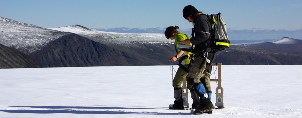
Geophysical Exploration applies physics principles to detect subsurface medium distribution patterns. This technology infers geological structures, ore body locations, and groundwater distribution by measuring physical field variations in the crust.
Key physical parameters include:
- Density contrasts (Gravity surveys)
- Magnetic signatures (Magnetic surveys)
- Electrical properties (Electrical prospecting)
- Seismic velocities (Seismic surveys)
- Radioactive intensity (Radiometric surveys)
2. Technical Classification Framework
Based on field source properties, geophysical methods divide into natural field and artificial field categories:
Natural Field Methods:
- Gravity surveys: Utilizing Earth’s gravitational anomalies
- Magnetic surveys: Measuring geomagnetic variations
- Natural potential methods: Observing spontaneous underground currents
Artificial Field Methods:
- Electrical prospecting: Artificial current injection with resistivity measurement
- Seismic surveys: Artificial elastic wave excitation
- Electromagnetic methods: Artificial electromagnetic field generation
Ⅱ. Deep Dive into Electrical Prospecting Technologies
1. Fundamentals of DC Resistivity Methods
DC Resistivity Methods form the foundation of electrical prospecting. Based on Ohm’s Law, these techniques inject stable current through surface electrodes and measure potential differences to calculate resistivity values.
Key Array Configurations:
- Symmetric four-electrode arrays (Schlumberger/Wenner)
- Dipole-dipole arrays
- Pole-dipole configurations
2. Electrical Resistivity Tomography (ERT)
Electrical Resistivity Tomography (ERT) represents the digital revolution in electrical prospecting. This technology employs multi-electrode arrays (typically 48-256 electrodes) with computer-controlled automated data acquisition.
2D ERT Characteristics:
- Linear electrode deployment along survey lines
- Vertical cross-section resistivity profiling
- Ideal for linear infrastructure projects (roads, pipelines)
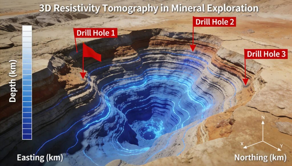
3D ERT Breakthroughs:
- Grid-based electrode arrays
- Volumetric subsurface imaging
- Perfect for 3D ore body localization and cavity detection
Technical Advantages:
- High resolution: Detects geological features down to 0.5m scale
- Wide depth range: Standard 50-200m, deep surveys up to 1000m
- Rich information: Simultaneous resistivity and chargeability acquisition
3. Induced Polarization (IP) Principles and Applications
Induced Polarization (IP) serves as the premier tool for locating metallic sulfide deposits. When artificial current shuts off, ore particle surfaces generate slowly decaying secondary potentials.
IP Measurement Parameters:
- Chargeability: Reflects mineralization intensity
- Time constants: Distinguish mineral types
- Frequency dependence: Identifies different polarization mechanisms
Target Minerals:
- Copper, lead-zinc sulfide deposits
- Gold ores (especially pyrite-associated types)
- Nickel-cobalt and uranium deposits
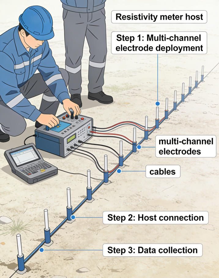
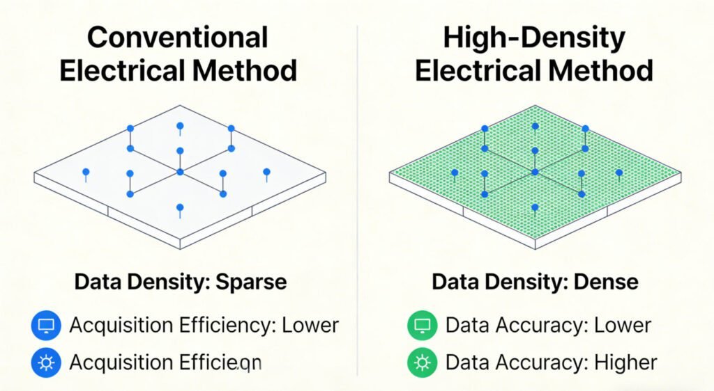
4. High-Density Electrical Method Innovations
High-Density Electrical Methods integrate traditional electrical surveying with ERT advantages, enabling efficient dense sampling.
Technical Features:
- Adjustable electrode spacing (1-5m)
- Automated rolling measurement systems
- Real-time data quality monitoring
Ⅲ. Detailed Analysis of Specialized Techniques
1. Vertical Electrical Sounding (VES)
Vertical Electrical Sounding (VES) specifically investigates resistivity variations with depth. By progressively expanding current electrode spacing, the technique obtains resistivity information at different depths.
Application Scenarios:
- Groundwater aquifer detection
- Bedrock depth investigation
- Loose layer thickness measurement
2. DC Resistivity Sounding
This technique acquires vertical resistivity profiles by varying electrode spacing, serving as a fundamental tool for engineering geological surveys.
Operational Essentials:
- Electrode spacing increases logarithmically
- Maximum AB/2 distance should reach 1.5x target depth
- Eliminate surface heterogeneity effects
3. Comparison: 2D vs 3D Resistivity Imaging
| Technical Dimension | 2D Resistivity Imaging | 3D Resistivity Imaging |
|---|---|---|
| Electrode Layout | Linear array | Grid array |
| Data Density | Medium | High-density |
| Application Scope | Profile detection | Volumetric detection |
| Interpretation Accuracy | Good | Excellent |
| Cost Efficiency | High | Medium |
Ⅳ. Engineering Application Case Studies
1. Metallic Mineral Exploration Case
Project Background: Deep concealed ore body search in copper mining district
Technical Solution: Combined 3D ERT + IP survey
Implementation Process:
- Deployed 10×10 electrode grid, 20m spacing
- Acquired resistivity and chargeability data
- 3D inversion imaging
Results:
- Identified deep low-resistivity, high-chargeability anomalies
- Drilling verification confirmed commercial ore body
- 40% exploration cost reduction
2. Engineering Geological Investigation
Application: Large bridge pile foundation site selection
Technologies Used: High-density electrical method + seismic refraction
Technical Value:
- Rapid overburden thickness determination
- Fracture zone and weak interlayer identification
- Pile length design basis provision
3. Hydrogeological Survey Practice
Investigation Target: Groundwater search in arid regions
Technical Combination: VES + ERT
Key Discoveries:
- Aquifer depth confirmed at 30-80m
- Aquifer thickness estimated at 15-25m
- Well placement guidance, 60% success rate improvement
Ⅴ. Technical Selection and Quality Control
1. Method Selection Decision Tree
Mineral Exploration:
- Sulfide deposit search → IP method preferred
- Oxide deposit search → ERT with magnetic methods
- Deep ore body detection → Large-spacing ERT or CSAMT
Engineering Investigation:
- Shallow fine structures → High-density electrical method
- Bedrock surface detection → VES or microtremor surveys
- Karst detection → 3D ERT
2. Data Quality Assurance
Field Acquisition Essentials:
- Electrode grounding resistance below 2kΩ
- Avoid high-voltage lines and substations
- Suspend operations during thunderstorms
Data Processing Workflow:
- Outlier removal and data smoothing
- Topographic correction and geometric factor calculation
- Inversion imaging and geological interpretation
Ⅵ. Technology Trends and Future Outlook
1. Equipment Intelligence
- UAV-based electrical systems: For hazardous terrain
- Automated cruise acquisition: 3-5x efficiency improvement
- Real-time data transmission: Cloud processing and sharing
2. Method Integration Innovation
- Joint electrical-seismic inversion
- Gravity-magnetic-electrical comprehensive interpretation
- AI-assisted anomaly recognition
3. Application Expansion
- Urban underground space detection
- Environmental pollution monitoring
- Geothermal resource exploration
- Archaeological site investigation
Ⅶ. Conclusion
Geophysical exploration technology is undergoing profound digital and intelligent transformation. As a core branch, electrical prospecting demonstrates strong vitality in mineral exploration, engineering construction, and hydrogeological surveys through advanced technologies including ERT, IP, and high-density electrical methods.
Technical selection should follow “objective-oriented, economically reasonable, precision-matched” principles. For deep ore detection, 3D ERT combined with IP is recommended. For engineering surveys, high-density electrical methods offer significant advantages. For groundwater investigations, VES technology provides cost-effective solutions.
Looking ahead, with deep integration of artificial intelligence and IoT technologies, geophysical exploration will achieve higher precision, greater depth penetration, and enhanced intelligence, providing solid technical support for resource security and engineering construction.
References
- E. M. Purcell, H. C. Torrey, and R. V. Pound: Phys. Rev. 69 (1946) 37. https://journals.aps.org/pr/abstract/10.1103/PhysRev.69.37
- F. Bloch: Physica 17 (1950) 460. https://journals.aps.org/pr/abstract/10.1103/PhysRev.70.460
- H. Dong, H. Liu, J. Ge, Z. Yuan, and Z. Zhao: IEEE Trans. Instrum. Meas. 65 (2016) 898. https://ieeexplore.ieee.org/document/7393816
- G. S. Waters: Nature 176 (1955) 691. https://www.nature.com/articles/176691a0
- G. S. Waters and G. Phillips: Geophys. Prospect. 4 (1956) 1. https://onlinelibrary.wiley.com/doi/10.1111/j.1365-2478.1956.tb01392.x
- A W. Overhauser: J. Phys. Rev. 92 (1953) 411. https://journals.aps.org/pr/abstract/10.1103/PhysRev.92.411
- A. Abragam: J. Phys. Rev. 98 (1955) 1729. https://journals.aps.org/pr/abstract/10.1103/PhysRev.98.1729
- G. Breit and I. I. Rabi: J. Special Studies Papers 38 (1931) 2082. https://journals.aps.org/pr/abstract/10.1103/PhysRev.38.2082.2
- I. Solomon: J. Phys. Rev. 99 (1955) 559. https://journals.aps.org/pr/abstract/10.1103/PhysRev.99.559
- J. Lenz and S. Edelstein: IEEE Sens. J. 6 (2006) 631. https://ieeexplore.ieee.org/document/1634415
- N. Kernevez and H. Glenat: IEEE Trans. Magn. 27 (2002) 5402. https://ieeexplore.ieee.org/document/278852
- D. Duret, J. Bonzom, M. Brochier, M. Frances, J. M. Leger, R. Odru, C. Salvi, T. Thomas, and A. Perret: IEEE
Trans. Magn. 31 (1995) 3197. https://ieeexplore.ieee.org/document/490326