Welcome to Geotech!

GEOTEM-8 Transient Electromagnetic Method Instrument(TEM)
PRODUCT PARAMETERS
Description
 Overview
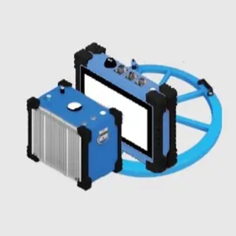
GEOTEM – 8 transient electromagnetic instrument is a high-end equipment designed for resource exploration and engineering geological survey, based on the principle of transient electromagnetic method (TEM, also known as time domain electromagnetic method). This method transmits pulses to the geological body to be measured through an ungrounded loop (coil), and uses the electric field as the field source (primary field) to stimulate the geological body to generate a secondary field. In the interval between the transmitted pulses, the receiving loop (coil) is used to receive the response of the secondary field changing with time. By analyzing the received secondary field data, the distribution characteristics of the geological body are analyzed, thereby solving geological problems.
Principle
Transient electromagnetic method (TEM), also known as time-domain electromagnetic method (TEM), uses ungrounded loop (coil) to emit pulses to the geological body under measurement. The electric field is used as the field source (primary field) to stimulate the geological body under measurement to generate secondary field. In the gap between transmitting pulses, the receiving loop (coil) is used to receive the response of the secondary field changing with time. The distribution characteristics of geological bodies can be analyzed from the secondary field data received so as to solve geological problems.
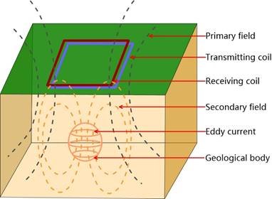
The magnetic field generated by eddy current at any time can be equivalent to the magnetic field generated by a horizontal loop of line current.
The outward diffusion of underground eddies is called the “smoke ring effect”.
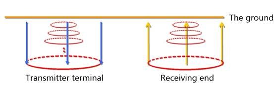
Current → magnetic field; The current breaks off → the magnetic field disappears; Magnetic field change → induced current → induced magnetic field
Ohmic consumption → induced current attenuation → induced magnetic field attenuation → induced weaker current
This process continues until the ohmic consumption of the earth runs out of magnetic field energy.
Core Advantages
Strengths
- High Efficiency: Rapid deployment for field operations.
- Superior Sensitivity: Pure secondary field observation excels in low-resistance anomaly detection.
- Non-Destructive: Maintains geological integrity during exploration.
- Strong Anomaly Response: Clear, high-resolution signals for intuitive interpretation.
- Integrated Survey: Simultaneous profile mapping and sounding provide comprehensive data.
Limitations
- Reduced vertical resolution in shallow layers.
- Limited exploration depth (<4 km).
- Susceptibility to natural/human electromagnetic interference.
- Apparent resistivity decreases with smaller coil size, differing from true formation resistivity.
Features
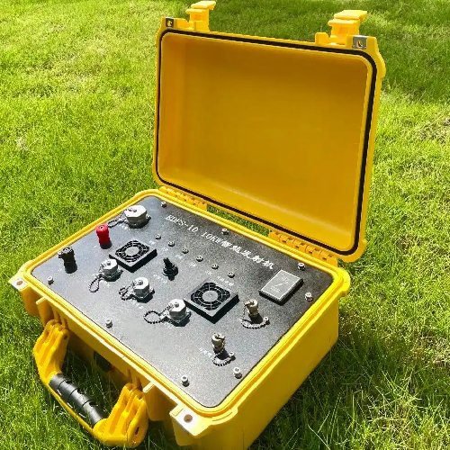
- Portable Transmitter System: Lightweight design for field mobility.
- High-Current Small-Coil Mode: Optimizes detection efficiency.
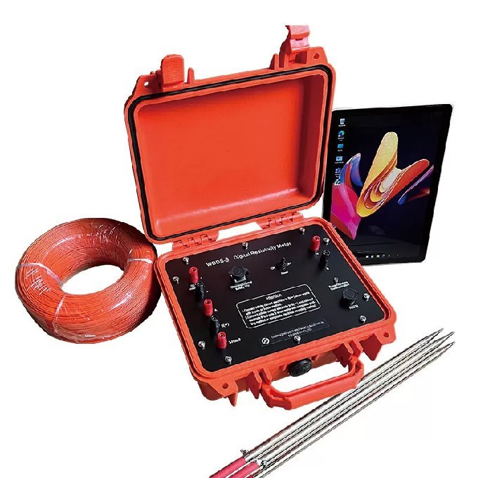
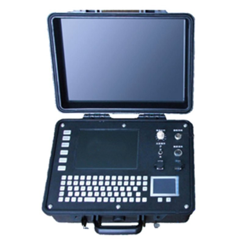
- Industrial PC Control: Windows-based operation for user-friendly management.
- Low-Power LED Display: Noiseless, energy-saving interface.
- User-Centric Safety: “Plug-and-play” design with built-in safety protocols.
- Ultra-High Sampling Rate: 1μs sampling for detailed data acquisition.
- Multi-Layer Anti-Interference: Advanced algorithms minimize random noise.
- One-Key Wizard: Simplifies field operations with automated workflows.
- Advanced Interpretation Software: Integrated data processing for in-depth analysis.
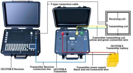
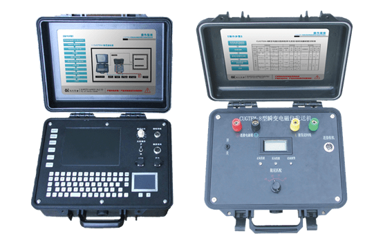
GEOTEM-8 Schematic diagram of intelligent deep resource exploration transient electromagnetic instrument system
Applications
Mineral Resource Exploration
Identifies boundaries of copper, gold, molybdenum, and other ore bodies within 800m depth.
Hydrogeology & Engineering Geology
Directly detects aquifers via resistivity anomalies (0.01nT sensitivity).
Oil, Gas & Renewable Energy
Penetrates high-resistivity overburden (e.g., salt domes) to map fracture systems.
Environmental & Infrastructure Safety
Monitors pollutant migration paths for remediation planning.
Technical Parameters
Comparison
Comparison table between exploration energy efficiency and transmit/receive coil unit
| Exploration energy efficiency | Transmitting coil | Receiving coil | |||||||||||
| Job type | Exploration depth | Transmitted power | Coil side length | Coil turns | Cable diameter | Length | Quantity | Color | Cable diameter | Length | Quantity | Color | |
| Tunnel | Advance200m | 100A | 1.5m | 4 | 6mm | 36m | 1 Root | Green | 8 cores 0.5mm | 34m | 1 Root | White | |
| Surface prospecting | 0-100m | 100A | 2m | 4 | |||||||||
| 100-400m | 100A | 5m | 2 | 6mm | 10m | 2 Root | Black | 8 cores 0.5mm | 10m | 2 Root | White | ||
| 10m | 1 | 15m | 2 Root | Red | |||||||||
| 400-600m | 200A | 5m | 2 | 10mm | 10m | 2 Root | Green | 15m | 2 Root | ||||
| 10m | 1 | 15m | 2 Root | Green | |||||||||
| 600-1300m | 200A | 25m | 1 | 20mm | 25.5m | 4 Root | Red | 8 cores 0.5mm | 25m | 4 Root | White | ||
The transmitting coil is the accumulation configuration, such as 0-1300m instrument, the configuration of 0-100m, 100-400m, 400-600m, 6-1300m corresponding to the four groups of coil group accumulation.
Receiving coil configuration: 0-600m instrument configuration 100-400m /400-600m corresponding to the coil group, 0-1300 m instrument configuration 0-100m and 600-1300m corresponding to the 2 groups of coil group accumulation.
Technical Parameters
Receiver performance index
| Project | Parameter |
| A/D converter | 16Bit |
| Dynamic range | 140dB |
| Sampling rate | 1μs、4μs、16μs、 |
| Number of acquisition channels | 2 |
| Background noise | 1μV |
| Voltage measuring range | -200V-200V |
| Voltage measurement resolution | ≤300nV |
| Measurement accuracy | 0.1% |
| Input gain range | 1/80-8000 |
| Minimum sampling interval | 4μs |
| Noise suppression | >100dB |
| Passband | 0-500kHz |
| Stacking number | 1-65535 |
| Computer system | PC104 industrial control, 8.4 “color LCD display screen (full Windows operating interface) |
| Data storage | 1G(Expandable) |
| Storage capacity | ≥30,000 measuring points |
| Data transmission | USB2.0 |
| Power supply | Built-in battery can guarantee more than 6 hours of operation, and can be connected to the external 9-18VDC |
| Dimension | 403mm×330mm×178mm(Length x width x height) |
| Weight | 8kg |
| Operating temperature | -10℃-50℃ |
Transmitter performance index
| Project | Parameter |
| Transmitting voltage(V) | 36-57 |
| Transmitting current intensity(A) | 25、50、100、200 |
| Current pulse width(ms) | 10、20、40 |
| Transmitting waveform | Bipolar square wave with duty cycle of 1:1 |
| Maximum transmitting power(KW) | 12 |
| Synchronous mode | Cable synchronization |
| Turn-off time | It varies with the size of the supply current and the sending coil,0.5-300μs |
| Dimension | 312mm×274mm×136mm(Length x width x height) |
| Weight | 2kg |
| Operating temperature | -10℃-50℃ |
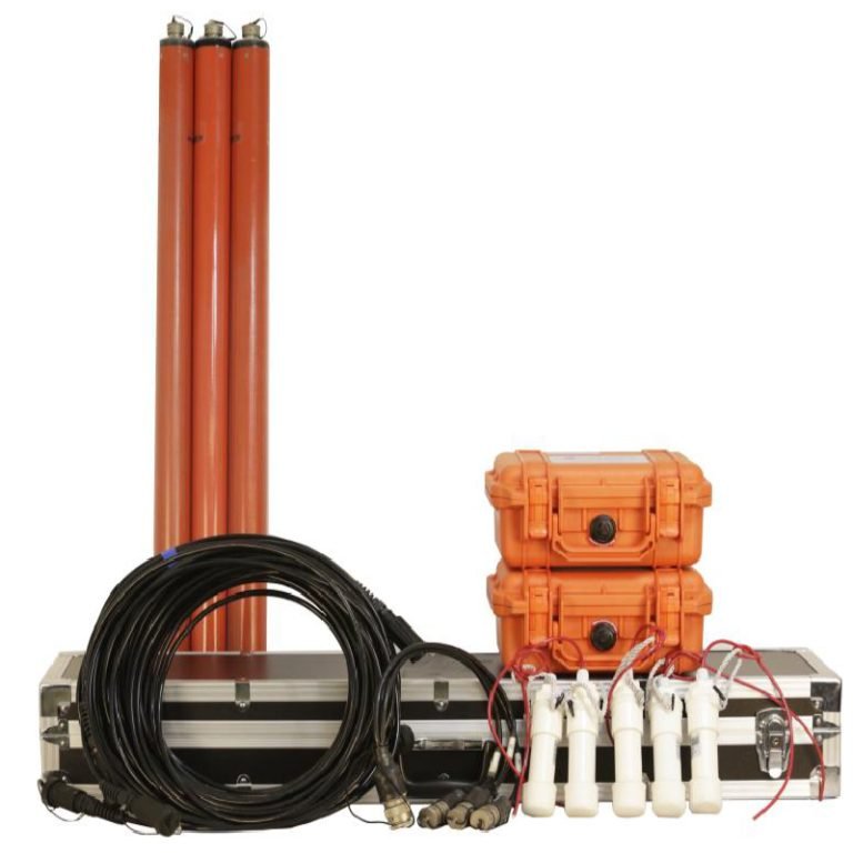
Configuration
| NO. | Component | Name | Quantity |
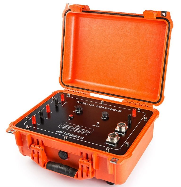
| 1 | Main engine | GEOTEM-8 receiver | 1 |
| 2 | GEOTEM-8 transmitter | 1 | |
| 3 | Accessories | Transmitter battery box | 1 |
| 4 | Transmitter charger | 1 | |
| 5 | Receiver charger | 1 | |
| 6 | USB interface cable | 1 | |
| 7 | Transmitter power black and red connection cable | 2 | |
| 8 | Transmitter transmitting coil yellow and green connection wire | 2 | |
| 9 | Transmitter receiver wired | 1 | |
| 10 | Y-type connection cable | 1 | |
| 11 | Aviation plug and transmitter coil screw | Several | |
| 12 | Software | Ground transient electromagnetic interpretation software(Usb flash disk) | 1 |
| 13 | File | GEOTEM-8 specification | 1 |
| 14 | GEOTEM-8 product certificate | 1 | |
| 15 | GEOTEM-8 product warranty card | 1 | |
| 16 | GEOTEM-8 product packing list | 1 | |
| 17 | Product publicity materials | 1 | |
| 18 | Device | 10m transmitting line | 2 |
| 19 | 15m transmitting line | 2 | |
| 20 | 10m transmitting line | 4 | |
| 21 | 10m receiving line | 4 | |
| 22 | 15m receiving line | 4 | |
| 23 | Instrument case and bag | Portable backpack | 2 |
| 24 | GEOTEM-8 receiver package | 1 | |
| 25 | GEOTEM-8 transmitter, device coil, accessories packing box | 3 |
Case Studies
Case 1:Application in detection of goaf
Exploration content
Water – filled goaf exploration of a coal mine in Renyi Town, Shanxi Province
Device layout
5*5m transmitting/receiving coil, transmitting current 200A
Description
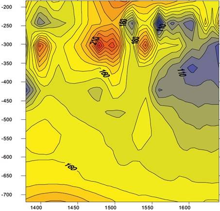
There are mainly coal-bearing strata in the working area, the total thickness is about 150m, among which there are multi-layer or local mining coal seam, the mining depth of coal seam is about 400m.
Lay out a measuring line, the points are 20m apart, the number of measuring points is 15, and the mileage is 280m.
As can be seen from the figure on the right, the depth of 300-400m, the mileage of 1550m and the value of 1700m are low-resistivity anomalies, which are determined to be the mined-out area of coal mine, completely consistent with the results of drilling data.
Case 2: Application in detection of goaf
Exploration content
Coal seam goaf exploration in Northeast China
Device layout
1*1m-5*5m transmitting/receiving coil
Description
The blue part in the figure on the right is the distribution of the goaf of coal seam.
Case 3:Engineering cases of detection in non-metallic mine goaf
Device layout
Exploration content
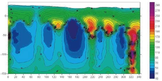
Guangxi Hechi Jintai Mining Co., LTD., large water-filled cave exploration under tailings pond.
2.5*2.5m transmitting/receiving coil, transmitting current 100A.
Description
As can be seen from the resistivity profile, the maximum low-resistance zone (No. 1) is concentrated in the range of 50-70m and the depth of 50-180m, which is consistent with the area where the mine party suspects the karst cave is located. No. 2 low resistance zone is 20-30m in mileage and 150-250m in depth. It has certain connectivity with No. 1 low resistance zone, which may be caused by the connection of karst caves or the larger volume of karst caves. The results are consistent with the actual results after the drilling verification in the mine and the verification in the human.
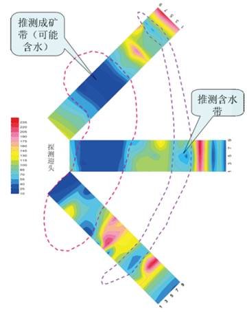
Case 4:Water project case
Exploration content
Advanced water exploration in Donghewan Iron Mine, Kaidong Industry and Trade Group, Wuan City, Hebei Province.
Device layout
1.5*1.5m transmitting/receiving coil, transmitting current 200A.
Description
The conjectural result on the right is verified by the mine side and is consistent with the actual situation.
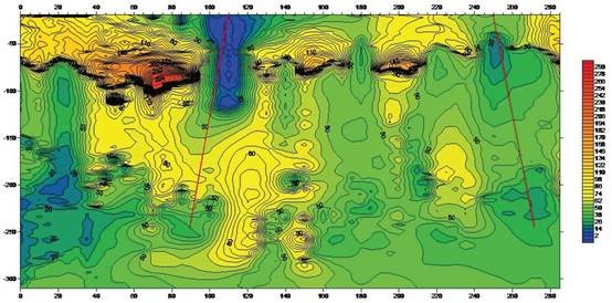
Case 5:Application in detecting new structures
Exploration content
A fault structure exploration in Hebei Province
Device layout
Central loop device, 1*1m transmitting/receiving coil
Description
As can be seen from the resistivity profile, there are low resistance anomalies under the surface 110m and 250m away from the starting point of the measurement line, which may be low resistance anomalies after the fissure is filled with water.
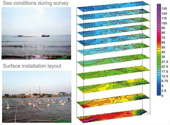
Case 6: Application in detecting new structures
Exploration content
Fault structure detection within 300m of a submarine rock in Shandong Province.
Device layout
Central loop device, 20*10m transmitting/receiving coil.
Description
Resistivity contour maps of different depths, in which the red lines are inferred faults.
FAQ
In gravity exploration (SI), what is the unit of gravity? How to convert gravity units between SI and CGS?
What are gravitational field and gravitational potential?
What is the normal gravity field of the earth? What are the rules for the change of the normal gravity field with latitude and altitude?
What is the relationship between gravitational field strength and gravitational acceleration?
What is gravity exploration?