Welcome to Geotech!

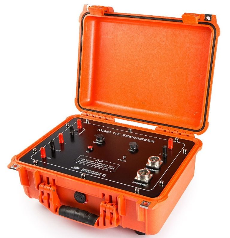
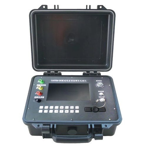
GEOTEM-GKII Tunnel Advanced Prediction Transient Electromagnetic Instrument
PRODUCT PARAMETERS
Description
 Current Industry Problems
Modern tunnel engineering is facing growing challenges from increasingly complex geological environments and longer tunnel lengths, making geological advanced prediction more critical in the excavation process. The main risks currently include:
- Karst: Common karst forms in tunnel construction include dissolution-formed karst trenches or grooves, sinkholes, karst caves, underground rivers, etc.
- Gob Areas: Metal and non-metal mine gobs are accompanied by risks of water inrush, large-area roof collapse, surface subsidence, etc.
- Faults and Fissures: Surface displacement and underground vibrations caused by underground faults and fissures, and water in fissures and faults cause various damages to tunnels and shafts.
- Bedrock Stress: The secondary stress field formed by tunnel excavation changes the distribution of the original rock mass stress field and groundwater seepage field, affecting the stability of tunnel surrounding rocks and mountain bodies.
During the downward excavation of shafts, due to the need to penetrate layers downward, water seepage and spraying from the shaft walls are very severe, and there is basically more than 20 cm of water accumulation at the shaft bottom. Within 5 meters from the shaft bottom, there are cast concrete and steel formworks. Therefore, at the bottom of the shaft, TSP and radar do not have the on-site construction conditions at all. Objectively speaking, under the on-site construction conditions of most shafts at present, only transient electromagnetic method has the on-site construction conditions.
The advanced prediction by transient electromagnetic method is currently a feasible and effective prediction means for water-bearing bodies in China.
Overview
In modern tunnel engineering, geological risks such as karst development, gob water inrush, fault and fissure water damage, and bedrock stress deformation are increasingly prominent. Especially in shaft excavation, scenarios such as water accumulation and metal structure interference make traditional TSP and radar technologies difficult to apply.
Based on the principle of Transient Electromagnetic Method (TEM), GEOTEM-GKII excites the secondary field response of geological bodies by transmitting pulsed electromagnetic fields, and combines small-coil high-power technology to provide an advanced detection solution for tunnel full-space environment, effectively breaking through the prediction bottleneck under complex geological conditions and becoming the industry benchmark for advanced geological prediction in tunnels.
Principles
1. Principle of Transient Electromagnetic Method
The Transient Electromagnetic Method (TEM), also known as the time-domain electromagnetic method (TEM), uses an ungrounded loop (coil) to emit pulses to the measured geological body. The electric field is used as the field source (primary field) to stimulate the measured geological body to generate a secondary field. In the gap between transmitting pulses, the receiving loop (coil) is used to receive the response of the secondary field changing with time. The distribution characteristics of geological bodies can be analyzed from the received secondary field data to solve geological problems.
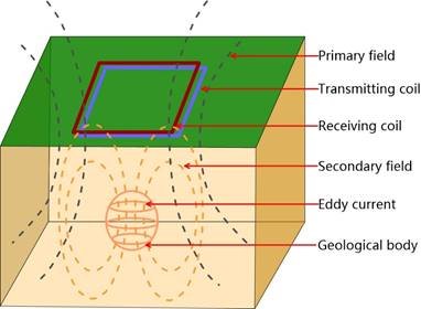
The magnetic field generated by eddy current at any time can be equivalent to the magnetic field generated by a horizontal loop of line current.
The outward diffusion of underground eddies is called the “smoke ring effect”.
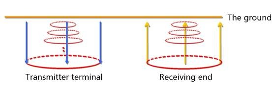
The physical process is as follows:
Current → magnetic field; The current breaks off → the magnetic field disappears; Magnetic field change → induced current → induced magnetic field
Ohmic consumption → induced current attenuation → induced magnetic field attenuation → induced weaker current
This process continues until the ohmic consumption of the earth runs out of magnetic field energy.
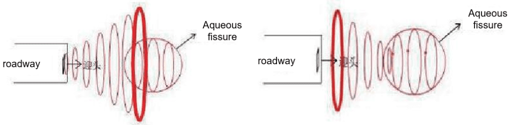
2. Principle of Tunnel Transient Electromagnetic Method
A transmitting coil capable of passing a certain wave current is arranged in the tunnel face to generate a secondary magnetic field in the surrounding space and induce a current in the conductive rock orebody around the tunnel. After power failure, the induced current decays with time due to heat loss, and the decay process is generally divided into early, middle and late stages.
The early electromagnetic field is equivalent to the high-frequency components in the frequency domain, which attenuates quickly and the skin depth is small. The late component is equivalent to the low-frequency component in the frequency domain, with slow attenuation and large skin depth.
The geoelectric characteristics at different depths can be obtained by measuring the secondary field changes with time after power failure.
Features
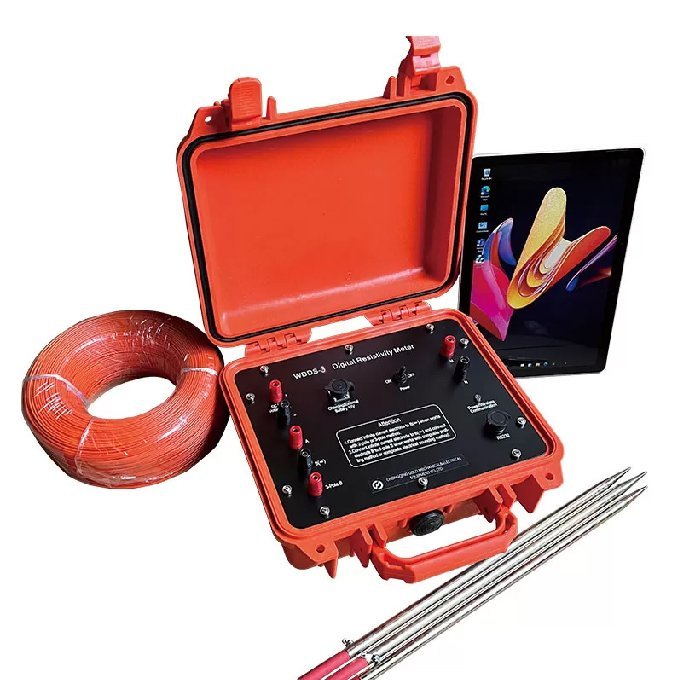
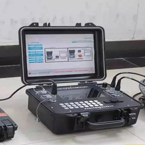
- Small size, light weight and convenient construction: Integrated design, with the receiver, transmitter and amplifier combined into one, making it easy to carry and construct.
- High performance and low power consumption: Using an industrial computer as the core controller, which not only improves performance but also reduces power consumption.
- The only small-coil and high-power transient electromagnetic detection equipment used in tunnels in China: The transmission current reaches 120A, which maximizes the detection accuracy.
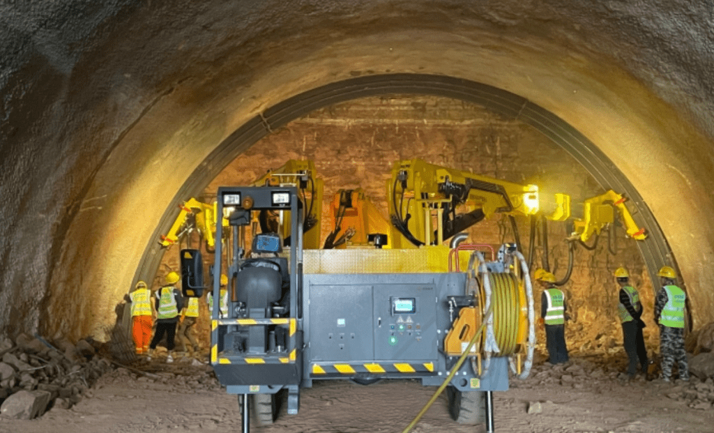
- Relatively simple site conditions: Large ironware, supports and drills on the face need to be moved away. Construction can also be carried out when there is water on the head-on ground or when the water output is large and a water pump is needed for pumping.
- Fast data processing speed: Generally, the geophysical data can be submitted within half a working day after the completion of on-site construction. Combined with the analysis of geological conditions, the possible water-rich areas can be predicted and forecasted to guide the drilling verification.
Applications
1. Tunnel Engineering Advanced Geological Prediction
- Application Scenarios: Tunnels, roadways, shafts, adits, and other full-space environments (detection range ≤150m).
- Core Functions:
- Geological Prediction: Identifies karst caves, faults zones, aquifers, and other geological anomalies ahead of the tunnel face (0-150m).
- Risk Mitigation: Detects water-rich strata and fractures to prevent water inrush and collapses, optimizing support designs.
- Design Support: Refines geological parameters (e.g., rock mass stability) to reduce construction risks and costs.
2. Non-Coal Mine Water Hazard Prevention
- Application Scenarios: Metal/non-metal mine roadways and excavation faces.
- Core Functions:
- Water Inrush Control: Maps water-rich fractures and goaf-induced water-conducting zones (e.g., Shanxi coal mine case: 40% water inflow reduction).
- Fracture Zone Detection: Identifies mining-induced water-conducting fracture zones in roof/floor strata.
3. Metal Ore Exploration and Safety
- Application Scenarios: Metal ore veins, underground chambers, and pipelines.
- Core Functions:
- Vein Tracking: Locates metal ore veins and distribution patterns.
- Safety Monitoring: Detects concealed water-bearing structures (e.g., faults zones) around chambers to prevent flooding.
4. Shallow Subsurface Investigation
- Application Scenarios: Subsurface structures within 150m depth.
- Core Functions:
- Urban Pipeline Networks: Identifies corrosion and leaks in metal pipelines (error <0.5m).
- Engineering Site Assessment: Evaluates geological stability for construction projects.
5. Infrastructure Safety Assessment
- Application Scenarios: Tunnels, underground chambers, and metro systems.
- Core Functions:
- Leakage Detection: Maps water infiltration paths around underground structures.
- Disaster Prevention: Identifies karst collapses and ground fissures threatening infrastructure.
Technical Parameters
| NO. | Project | Parameter |
| 1 | Master control machine | Military grade master control |
| 2 | A/D converter | 24Bit |
| 3 | Dynamic range | 140dB |
| 4 | Sampling rate | 1μs、4μs、16μs、 |
| 5 | Background noise | 1μV |
| 6 | Memory | 256MB |
| 7 | Hard disk | 4GB Electronic Disk (Expandable) |
| 8 | Port | USB |
| 9 | Monitor | 8.4 “TFT LCD screen |
| 10 | Transmitting current intensity | ≤60A |
| 11 | Current emission frequency | 75Hz、25Hz、12.5 Hz、6.25 Hz、3.125 Hz、1.5625 Hz |
| 12 | Transmitting coil specification | 1×1m-3×3m |
| 13 | Turn-off time | 0.5-300μs |
| 14 | Transmitting waveform | Bipolar rectangular wave |
| 15 | Power supply | Built-in battery |
| 16 | Stacking number | 1-9999 |
| 17 | Continuous working time | More than 6 hours |
| 18 | Dimension | 403mm×330mm×178mm(Length x width x height) |
| 19 | Operating temperature | -10℃-50℃ |
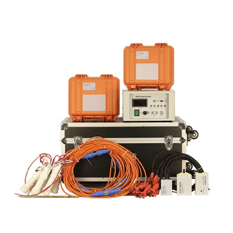
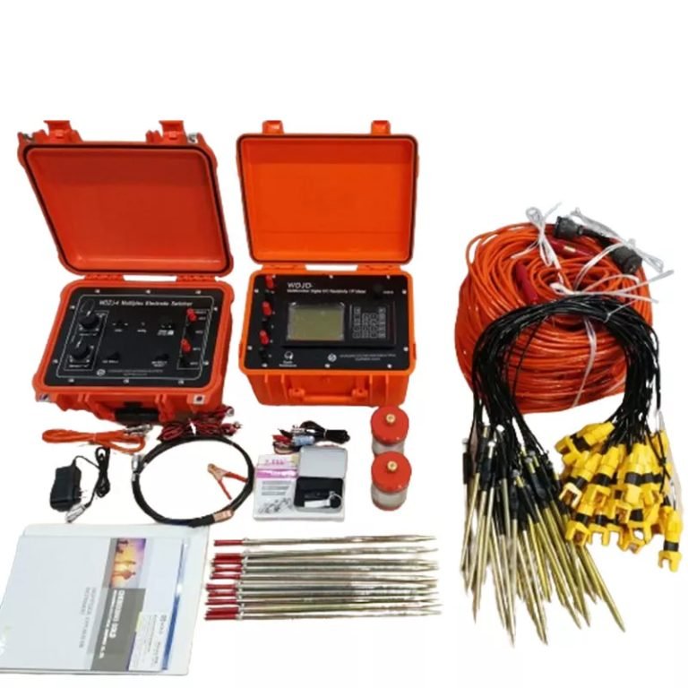
Product Configuration
| NO. | Component | Name | Quantity |
| 1 | Host | GEOTEM-GKII Transient Electromagnetic Instrument for Tunnel Advance Prediction (Integrated receiving and Transmitting) | 1 |
| 2 | Accessories | Host charger | 1 |
| 3 | USB interface cable | 1 | |
| 4 | Receiving coil connection wire | 1 | |
| 5 | Transmitting coil connection wire | 1 | |
| 6 | Tunnel advance probe rod | 2 | |
| 7 | Device | Transmitting coil | 1 |
| 8 | Receiving coil | 1 | |
| 9 | File | GEOTEM-GKII specification | 1 |
| 10 | GEOTEM-GKII product certificate | 1 | |
| 11 | GEOTEM-GKII product warranty card | 1 | |
| 12 | GEOTEM-GKII product packing list | 1 | |
| 13 | Product publicity materials | 1 | |
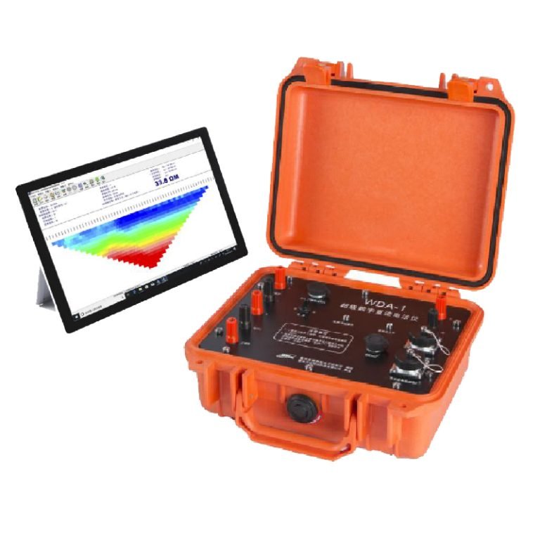
| 14 | Software | Transient electromagnetic interpretation software | 1 |
Cases
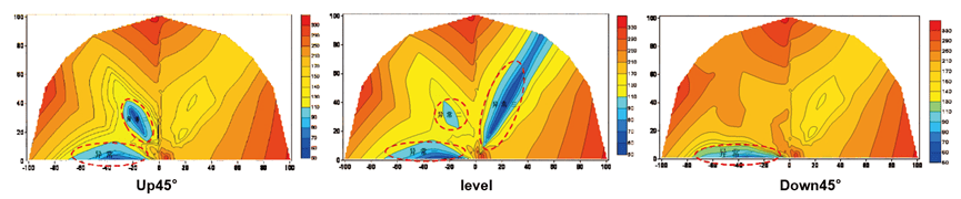
Case 1:Maojiahe Power Station Water Diversion Tunnel – TEM Advanced Detection for Karst Water-rich Zones
- Investigation unit: Maojiahe Power Station.
- Investigation content: To find out the advance forecast in the process of water diversion tunnel excavation.
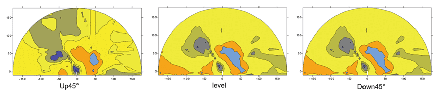
- Device layout: Construction layout and workload of the TEM exploration test. Three survey lines (up 45°, horizontally forward and down 45°) are arranged along the face of the water diversion tunnel excavation, and three measured profiles of advance detection are formed by moving the transmitting/receiving coils on the face of the face.
- Explanation: The blue low-resistivity anomaly in the right figure is presumed to be a water-rich area.
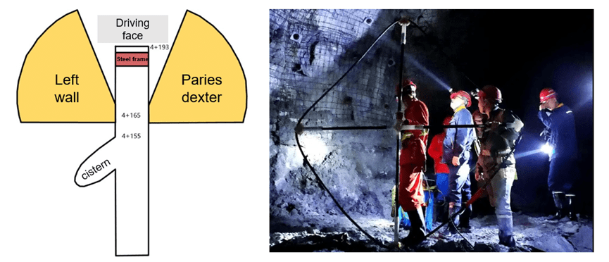
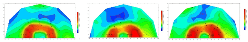
Case 2:Tunnel Pile No. 4+165 – TEM Prediction of Structural Fissure Water in Steel Frame & Water Accumulation Environment
- Survey content:The geological prediction of the left and right inclined forward parts of pile No. 4+165 is carried out, and the water richness of the detection area is compared and evaluated. Based on the detection results, a suitable location is selected as a new construction channel.
- Operation requirement:Three measuring lines were arranged on the left and right walls of the palm face respectively. Due to severe water discharge and steel frame in front of the palm face, relevant fan-shaped observation system was arranged in front of the palm face to detect water abundance on the left and right walls.
- Result description:The data show that along the axial direction of the tunnel, there are obvious low-resistance anomalies in the range of 0-45° to the left in front and 20-80m away from pile No. 165, and it is inferred that there may be a water-rich area of structure and fracture zone. There is an obvious low resistance anomaly in the range of 0-60° to the left of the front and 30-80m away from pile No. 165, and it is inferred that there may be crack water. There is an obvious low resistance anomaly in the range of 0-30° to the left of the front, 20-80m away from pile No. 165, and it is inferred that there may be crack water.
Case 3:Sujiapo Mine 300 North Roadway – TEM Detection of Gob Water Accumulation & Structural Water-rich Zones
- Survey content:Transient electromagnetic method for advanced water detection in 300 north roadway of Sujiapo Mine.
- Operation requirement:Three survey lines are arranged along the 300 north roadway (up 45°, along the bedding direction, down 45°), and three measured profiles of advance detection are formed by moving the transmit/receive coils on the palm surface.
- Result description:With the increase of mining life and mining depth, the hydrogeological conditions of the mine are becoming more and more complicated, and it belongs to the mine with complicated hydrogeological disasters. The threat of water damage in the mine mainly comes from two aspects: one is the water-filled gob area formed after the completion of the mining of the surrounding small phosphate mines; the other is that the terrain and geomorphologic conditions around the mine are relatively complex, and the structure is very rich in water. The blue anomalous area with low resistance delineated in the figure on the right is presumed to be the accumulated water goaf and the structural water rich area.
FAQ
In gravity exploration (SI), what is the unit of gravity? How to convert gravity units between SI and CGS?
What are gravitational field and gravitational potential?
What is the normal gravity field of the earth? What are the rules for the change of the normal gravity field with latitude and altitude?
What is the relationship between gravitational field strength and gravitational acceleration?
What is gravity exploration?