Welcome to Geotech!
ERT Equipment: 5 Essential Features for Precision Subsurface Mapping
TIPS:Electrical Resistivity Tomography Equipment has revolutionized subsurface exploration across industries. Discover the top 5 features of modern ERT equipment that deliver high-resolution 2D/3D imaging for geotechnical, environmental, and utility mapping applications. Learn how multi-electrode resistivity systems from Geotech Instrument Co., Ltd. provide non-destructive testing solutions with advanced software integration and portable field performance. ERT equipment ensures accurate underground imaging while reducing project risks and costs.

Ⅰ. Introduction: Why ERT Equipment Matters in Modern Geophysics
Electrical Resistivity Tomography (ERT) equipment stands at the forefront of non-invasive subsurface exploration. Unlike Ground Penetrating Radar (GPR) that struggles in conductive soils, electrical resistivity tomography equipment delivers consistent performance across diverse geological conditions. The global ERT market reached USD 382.6 million in 2024, growing at 6.4% CAGR. This growth reflects increasing demand from construction, environmental monitoring, and utility mapping sectors.
Geotech Instrument Co., Ltd. engineers advanced ERT equipment that bridges the gap between traditional DC resistivity methods and modern imaging requirements. Our systems serve geophysicists, environmental consultants, and infrastructure planners who require reliable subsurface data.
Ⅱ. Feature 1: Multi-Electrode Array Architecture for Rapid Data Acquisition
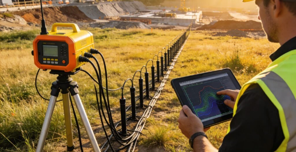
Modern multi-electrode resistivity systems revolutionize field efficiency. Traditional single-electrode setups require manual electrode repositioning, consuming hours per survey line. Our resistivity imaging systems deploy 60–120 electrode channels with automated switching.
This architecture delivers three advantages:
- Speed: Complete 2D profiles in minutes, not hours
- Density: Collect thousands of measurement points per line
- Consistency: Eliminate human error in electrode spacing
For utility mapping applications, this means rapid reconnaissance of large construction sites. While GPR requires grid-by-grid scanning, multi-electrode resistivity systems cover linear transects efficiently, detecting conductive utilities like metal pipes and cables through their resistivity contrasts against surrounding soil.
Ⅲ. Feature 2: True 3D Electrical Resistivity Tomography Capability
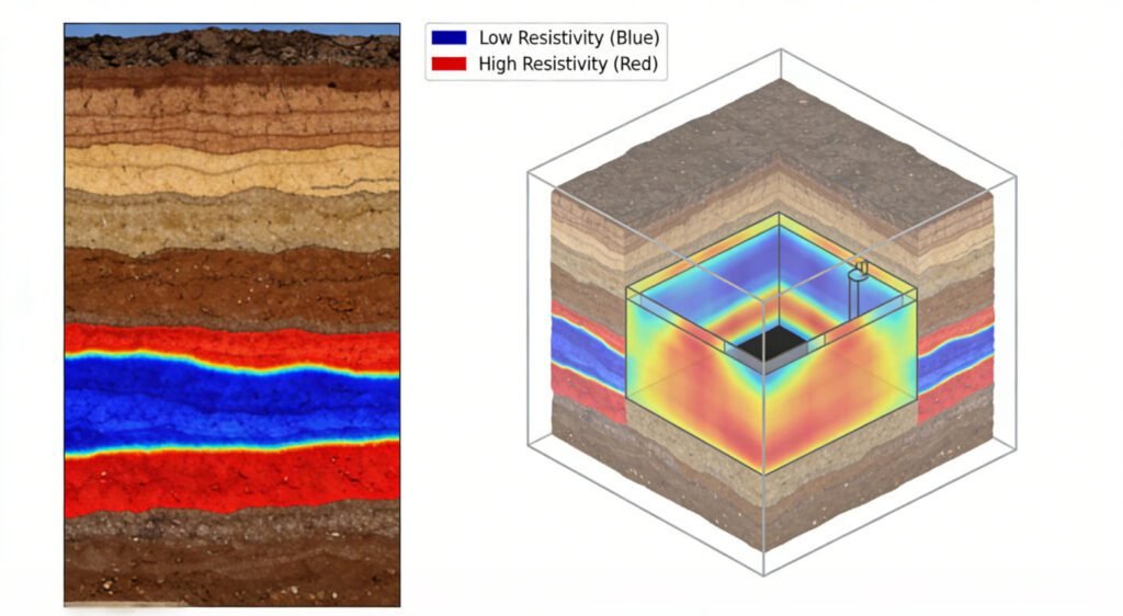
The shift from 2D to 3D electrical resistivity tomography represents a quantum leap in subsurface visualization. Our ERT equipment supports both 2D resistivity meter configurations for linear structures and full 3D electrical resistivity tomography for complex sites.
2D ERT excels at:
- Bedrock depth profiling
- Fault line mapping
- Linear utility tracing
3D ERT reveals:
- Volumetric contaminant plumes
- Cave systems and voids
- Complex utility networks in urban environments
A 2024 case study demonstrated 3D electrical resistivity tomography detecting a 15-meter-deep underground storage tank with 94.6% accuracy. This precision prevents costly excavation errors in utility mapping projects where unmapped tanks pose explosion risks.
Ⅳ. Feature 3: Integrated IP Functionality for Enhanced Discrimination
Advanced geoelectrical tomography equipment now includes Induced Polarization (IP) measurement capability. IP detects chargeability contrasts, distinguishing:
- Clay layers from metallic objects
- Mineral deposits from construction debris
- Water-saturated zones from dry utilities
This dual-mode operation transforms ERT equipment into versatile exploration tools. Environmental consultants use IP to identify landfill boundaries. Mining geologists locate ore bodies. Utility mapping teams differentiate between conductive pipes and natural clay lenses that GPR might misinterpret as utilities.
Ⅴ. Feature 4: Ruggedized Portable Design for Field Deployment
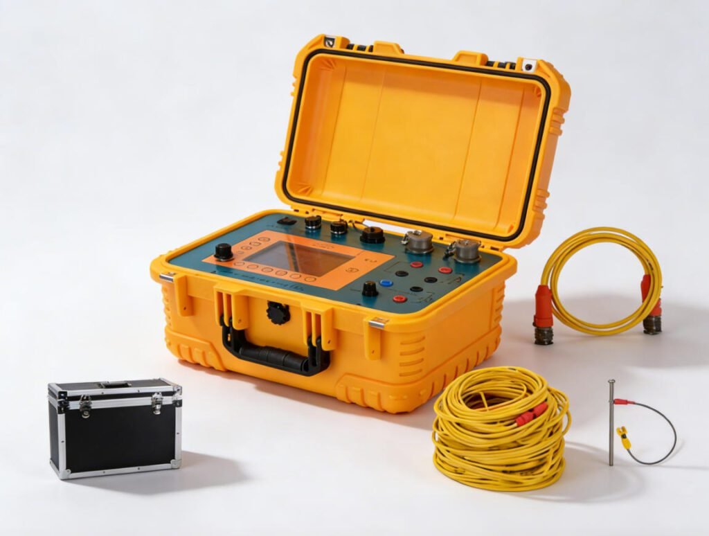
Field conditions demand durability. Our electrical resistivity tomography equipment features:
- Weatherproof enclosures (IP65 rating)
- Operating temperatures: -10°C to +50°C
- Lightweight electrode cables with Kevlar reinforcement
- Hot-swappable battery systems for continuous operation
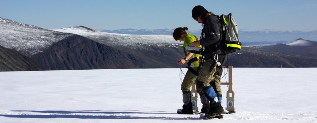
Portability extends ERT equipment applications beyond traditional geophysics. Archaeological teams survey remote sites. Emergency responders assess post-disaster ground stability. Utility mapping contractors navigate urban environments where vehicle access is limited.
The compact form factor enables utility mapping in constrained spaces—between buildings, under power lines, or inside existing structures where large GPR antennas cannot maneuver.
Ⅵ. Feature 5: Intelligent Software for Real-Time Visualization
Hardware performance depends on software integration. Our resistivity imaging systems include proprietary inversion algorithms that process data during acquisition. Key capabilities include:
- Real-time 2D/3D visualization: Watch resistivity models build as electrodes activate
- Automated noise filtering: Remove power line interference and telluric currents
- GPS integration: Georeference every measurement point
- Export compatibility: Direct output to CAD, GIS, and utility mapping databases
This software ecosystem reduces project timelines. Field crews validate data quality immediately, avoiding costly re-surveys. Office teams receive ready-to-interpret models, accelerating decision-making for construction and utility mapping projects.
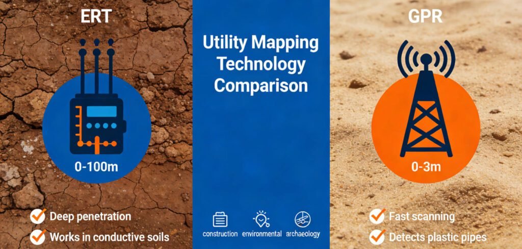
Ⅶ. ERT vs GPR: Choosing the Right Utility Mapping Technology
While this article focuses on ERT equipment, effective utility mapping often requires method integration. Understanding ERT’s strengths relative to GPR ensures optimal technology selection:
| Factor | ERT Equipment | GPR Systems |
|---|---|---|
| Soil Conductivity | Performs in clay, wet soils | Signal attenuates in conductive ground |
| Depth Penetration | Up to 100m (2D), 50m (3D) | Typically 2-3m for utility detection |
| Material Detection | Requires resistivity contrast | Detects dielectric changes |
| Non-metallic Utilities | Limited (unless tracer wires present) | Excellent for plastic pipes |
| Data Acquisition Speed | Moderate (automated arrays) | Fast (continuous scanning) |
For comprehensive utility mapping, Geotech recommends combined approaches: GPR for rapid area coverage and non-metallic pipe detection, electrical resistivity tomography equipment for deep utility confirmation and geological hazard assessment.
Ⅷ. Applications Across Industries
1. Geotechnical EngineeringERT equipment maps bedrock topography, identifies voids beneath foundations, and assesses slope stability. Pre-construction surveys prevent catastrophic failures.
2. Environmental Monitoring Track contaminant plumes in real-time. Monitor landfill integrity. Assess groundwater remediation effectiveness. Multi-electrode resistivity systems enable long-term monitoring with permanent electrode installations.
3. Mining and Mineral Exploration Detect ore bodies, map alteration zones, and identify groundwater inflows that threaten mine safety. IP functionality enhances target discrimination.
4. Archaeological Prospecting Locate buried structures without excavation. 3D electrical resistivity tomography reveals building foundations, tombs, and cultural layers with sub-meter precision.
5. Utility Mapping and Infrastructure While not the primary tool for shallow utility detection, ERT equipment excels at:
- Deep utility confirmation (>3m depth)
- Detecting abandoned mines and voids that threaten utilities
- Mapping geological hazards (sinkholes, faults) affecting infrastructure
- Locating metallic utilities in GPR-challenging environments (clay-rich soils)
Ⅸ. Conclusion: Investing in Advanced ERT Equipment
The evolution of electrical resistivity tomography equipment from manual instruments to automated multi-electrode resistivity systems has transformed subsurface exploration. Geotech Instrument Co., Ltd. delivers ERT equipment that combines hardware durability, software intelligence, and versatile 2D/3D imaging capabilities.
Whether conducting environmental assessments, geotechnical investigations, or specialized utility mapping in challenging terrain, modern resistivity imaging systems provide the accuracy and efficiency that modern projects demand. Contact Geotech to configure the optimal ERT equipment solution for your specific application requirements.
References
- E. M. Purcell, H. C. Torrey, and R. V. Pound: Phys. Rev. 69 (1946) 37. https://journals.aps.org/pr/abstract/10.1103/PhysRev.69.37
- F. Bloch: Physica 17 (1950) 460. https://journals.aps.org/pr/abstract/10.1103/PhysRev.70.460
- H. Dong, H. Liu, J. Ge, Z. Yuan, and Z. Zhao: IEEE Trans. Instrum. Meas. 65 (2016) 898. https://ieeexplore.ieee.org/document/7393816
- G. S. Waters: Nature 176 (1955) 691. https://www.nature.com/articles/176691a0
- G. S. Waters and G. Phillips: Geophys. Prospect. 4 (1956) 1. https://onlinelibrary.wiley.com/doi/10.1111/j.1365-2478.1956.tb01392.x
- A W. Overhauser: J. Phys. Rev. 92 (1953) 411. https://journals.aps.org/pr/abstract/10.1103/PhysRev.92.411
- A. Abragam: J. Phys. Rev. 98 (1955) 1729. https://journals.aps.org/pr/abstract/10.1103/PhysRev.98.1729
- G. Breit and I. I. Rabi: J. Special Studies Papers 38 (1931) 2082. https://journals.aps.org/pr/abstract/10.1103/PhysRev.38.2082.2
- I. Solomon: J. Phys. Rev. 99 (1955) 559. https://journals.aps.org/pr/abstract/10.1103/PhysRev.99.559
- J. Lenz and S. Edelstein: IEEE Sens. J. 6 (2006) 631. https://ieeexplore.ieee.org/document/1634415
- N. Kernevez and H. Glenat: IEEE Trans. Magn. 27 (2002) 5402. https://ieeexplore.ieee.org/document/278852
- D. Duret, J. Bonzom, M. Brochier, M. Frances, J. M. Leger, R. Odru, C. Salvi, T. Thomas, and A. Perret: IEEE
Trans. Magn. 31 (1995) 3197. https://ieeexplore.ieee.org/document/490326
