Welcome to Geotech!



GEO-GPR-100 MHz Single-Frequency Geophysical Radar Series | 100MHz Shielded








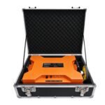

PRODUCT PARAMETERS
Description
 Abstract
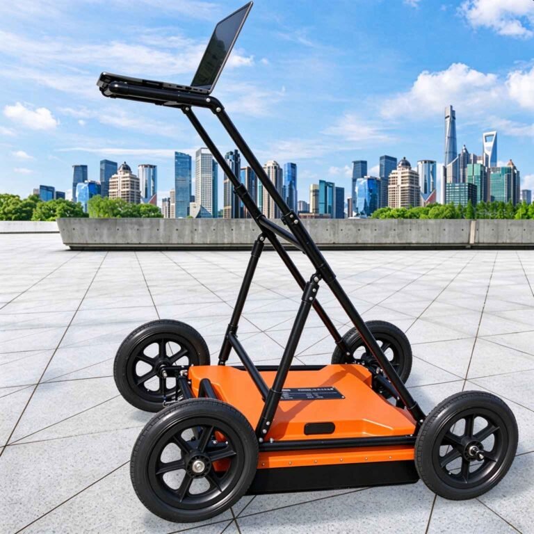
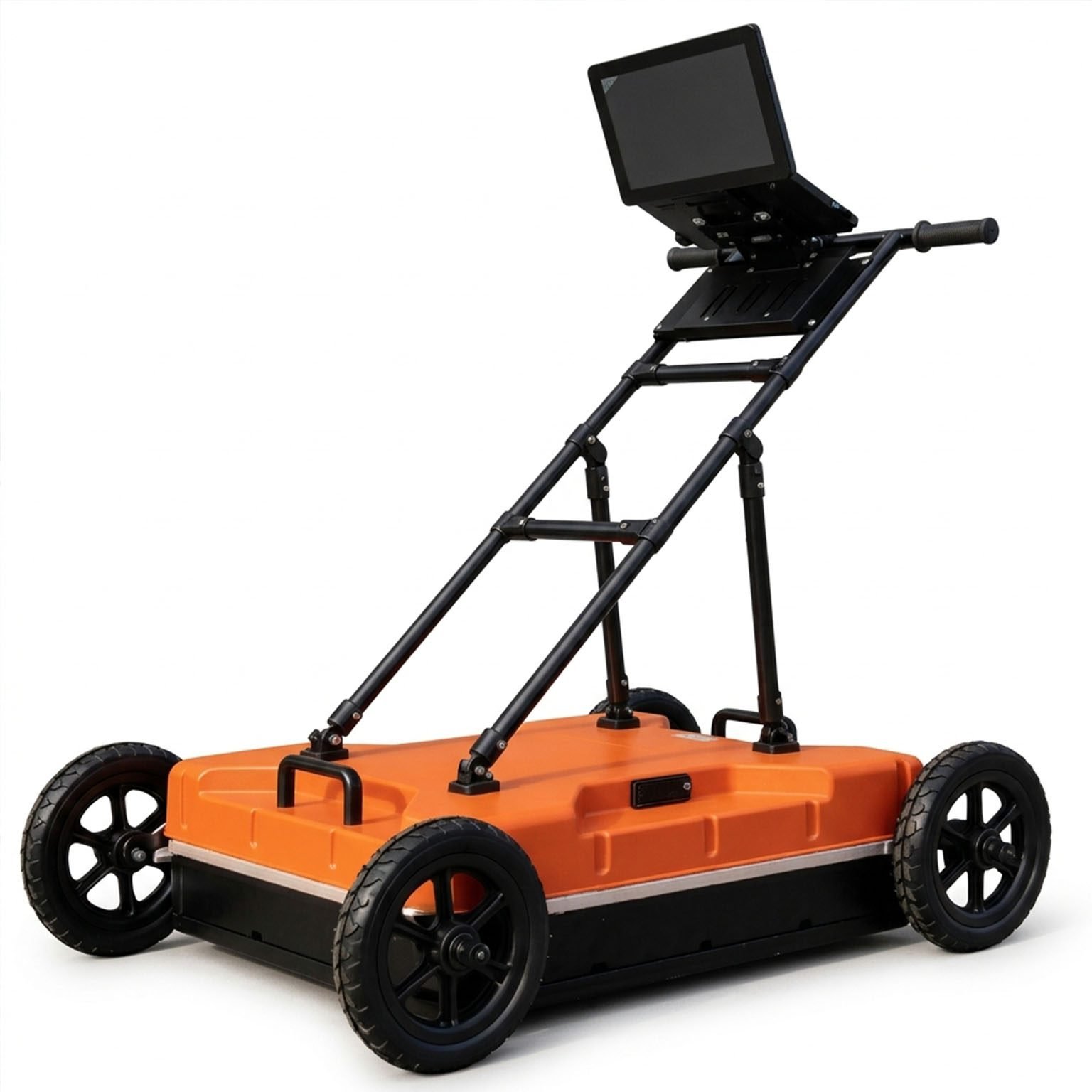
The GEO-GPR-100MHz is a 100 MHz ground penetrating radar built for deep subsurface survey — the lowest-frequency model in the GEO-GPR geological radar series. Its monostatic shielded antenna integrates transmitter, receiver and battery in a single housing, so a deep-penetration GPR survey needs no separate mainframe, no cables between host and antenna, and no cart-mounted control unit. In dry, low-loss rock it resolves targets down to 30 m; in typical overburden and engineered fill it delivers 4–25 m, in line with municipal GPR investigation codes.
Low frequency is the only way a pulse radar reaches depth: a 100 MHz antenna radiates a roughly 10 ns pulse whose energy attenuates slowly enough to return reflections from bedrock interface, karst voids, fracture zones and water-bearing ground ahead of a tunnel face. Published back-analysis of tunnel advance prediction work reports 100 MHz as the optimum frequency for identifying adverse geology 4–15 m ahead of the face, with the strongest returns coming from water-filled rather than air-filled anomalies. Where high-frequency antennas deliver detail, the GEO-GPR-100MHz delivers reach — and pairs with the 400 MHz and 900 MHz models to complete both ends of the profile.
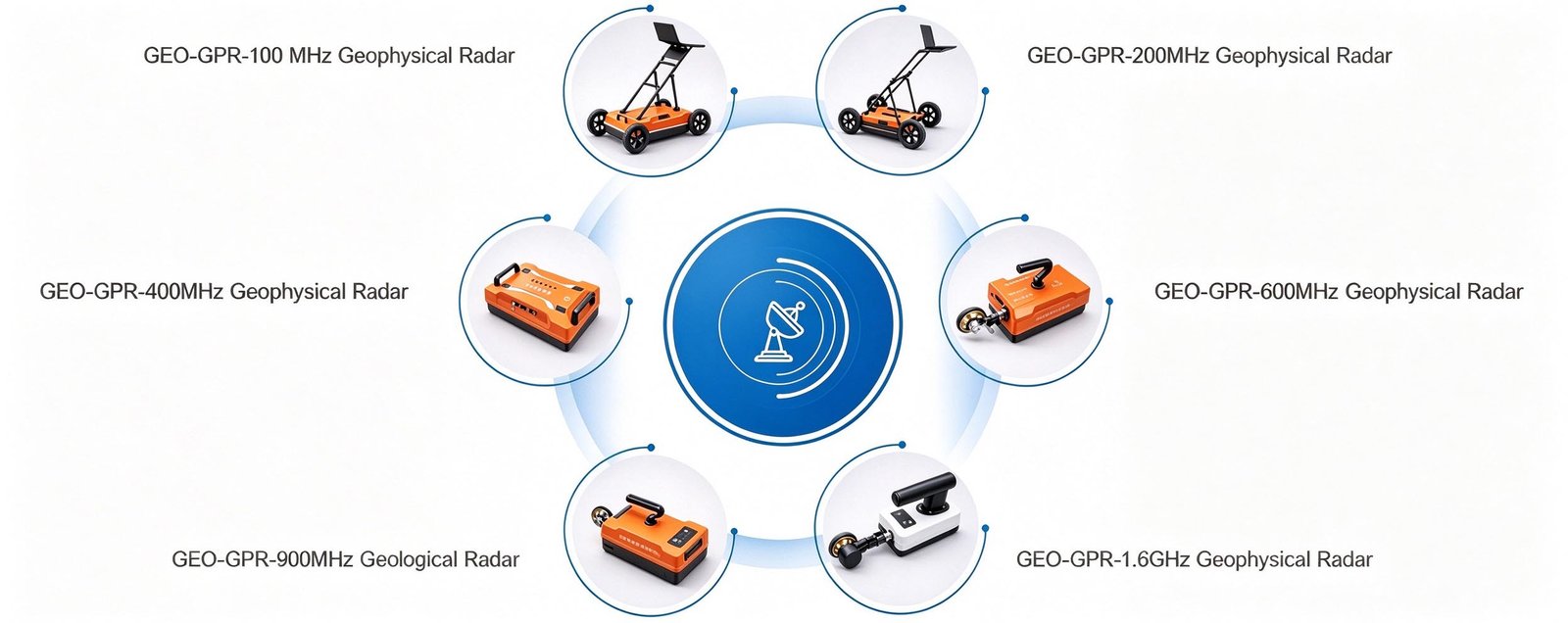
Technical Highlights
- Deep-penetration monostatic antenna. Transmit and receive electronics share one shielded housing, putting pulse energy into the ground rather than into cabling. Depth capability reaches 30 m in dry, low-loss rock at relative permittivity 4–9.
- Shielding that works at low frequency. Faraday shielding is what allows a 100 MHz radar to be used beside highways, high-voltage lines and rebar-dense structures, where an unshielded horn antenna records interference instead of geology. Signal-to-noise ratio is better than 160 dB.
- 350 traces per second. The scan rate supports rapid linear survey along roads, dam axes, tunnel inverts and site transects, covering long profiles in a single pass rather than repeated lanes.
- Wireless, self-contained, cold-rated. A wireless link of more than 50 m to tablet or laptop, at least 8 hours of continuous logging on the internal battery, and an operating range of −30 °C to +70 °C — the widest temperature band in the series, suited to high-altitude and winter tunnel portals.
Features
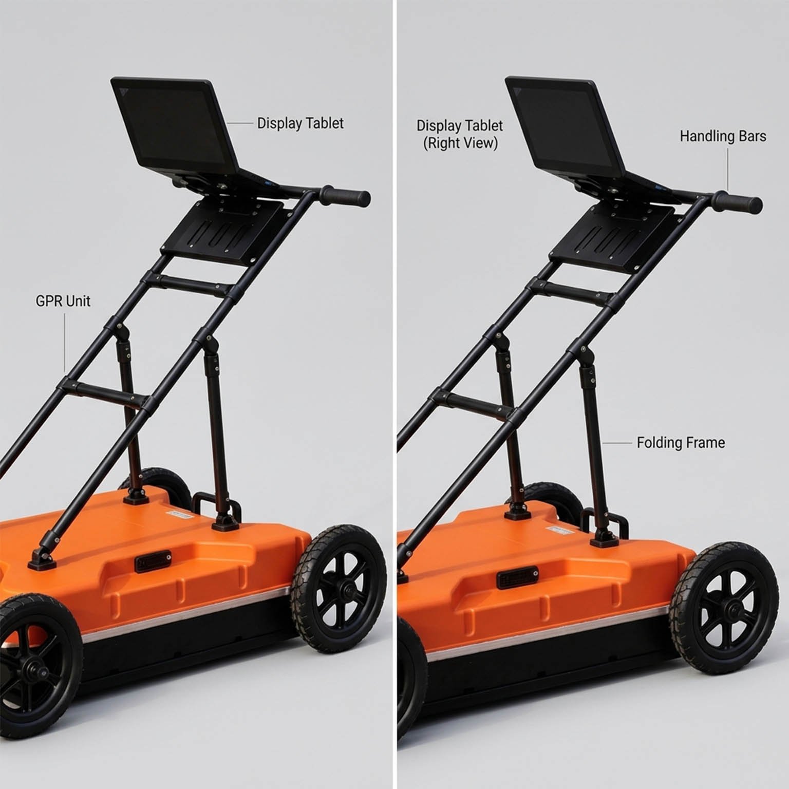
- Host-antenna integrated design — one unit carries transmitter, receiver and power
- Built-in large-capacity lithium battery, ≥8 h continuous acquisition
- Rugged three-proof housing: dustproof, waterproof, shockproof
- Wireless host-to-computer link, >50 m operating range
- Four acquisition modes: point-by-point, distance-triggered, continuous free-run and GNSS/GPS-triggered
- Real-time pseudo-colour, stacked-waveform and grayscale display with live gain, band-pass and Dewow filtering
- Multi-band antenna family — the same receiver accepts 200 MHz, 400 MHz, 600 MHz, 900 MHz and 1.6 GHz antennas
- High detection and positioning accuracy for target depth and lateral location
- Continuous, long-profile logging with automatic pseudosection assembly
- Field-proven in tunnel, karst, road and dam investigation projects
Applications

The 100 MHz antenna is selected when the target is deep rather than small. Typical survey tasks:
| Application | What the GEO-GPR-100MHz resolves | Typical depth |
| Tunnel advance geological prediction | Karst cavities, fracture zones and water-bearing ground ahead of the tunnel face | 4–20 m ahead of face |
| Karst and subsurface void mapping | Sinkholes, soil cavities, collapse features and covered dissolution channels | 5–25 m |
| Mined-out area and goaf survey | Collapsed zones, water-filled stopes and the boundary of worked-out ground | 10–30 m |
| Dam and levee foundation investigation | Solution channels, loose layers and seepage pathways beneath and within the embankment | 5–15 m |
| Bedrock and overburden thickness mapping | Bedrock relief, weathered profile depth, palaeochannel infill | 10–25 m |
| Landslide and structural geology | Slip-surface depth, sheared zones and thickness of unconsolidated deposits | 10–20 m |
| Subgrade and deep utility investigation | Loose or saturated subgrade zones and deeply buried structures | 3–12 m |
For rebar, concrete cover, shallow services and archaeological detail, select the 600 MHz, 900 MHz or 1.6 GHz antenna — at 100 MHz the wavelength is too long to resolve features at that scale.
Typical Performance Reference
Depth and resolution are properties of the ground as much as of the antenna. The table below gives expected performance of a 100 MHz antenna across common media. Vertical resolution is taken as approximately λ/4, with λ = c / (f · √εr).
| Medium | Relative permittivity εr | Wave velocity | Effective depth | Vertical resolution |
| Dry sand, gravel, asphalt | 4 | 0.150 m/ns | 15–30 m | ≈37 cm |
| Moist soil, general overburden | 6 | 0.122 m/ns | 10–25 m | ≈31 cm |
| Sound limestone, concrete | 9 | 0.100 m/ns | 5–20 m | ≈25 cm |
| Wet clay, basalt | 16 | 0.075 m/ns | 3–10 m | ≈19 cm |
| Saturated fine-grained soil | 25 | 0.060 m/ns | 2–6 m | ≈15 cm |
Conductive and saline ground attenuates the signal sharply; in saturated clays expect single-digit depth regardless of antenna rating. A site trial is recommended where depth is the controlling project requirement.
Specifications
| Parameter | Specification |
| Antenna type | Monostatic shielded antenna |
| Centre frequency | 100 MHz |
| Scan rate | 350 traces/s |
| A/D conversion | 18 / 32 bit |
| Signal-to-noise ratio | Better than 160 dB |
| Maximum detection depth | 30 m (dry, low-loss ground) |
| Acquisition modes | Point-by-point, distance-triggered, continuous |
| Display modes | Pseudo-colour image, stacked waveform, grayscale image |
| Continuous operating time | ≥8 h |
| Wireless data range | >50 m |
| Operating voltage | 10–15 V DC |
| Operating temperature | −30 °C to +70 °C |
| Unit weight | 27.95 kg (antenna with integrated electronics and battery) |
| Series compatibility | Accepts GEO-GPR 200 / 400 / 600 / 900 MHz and 1.6 GHz antennas |
Full technical documentation, calibration records and site demonstration data are available on request.
 Options & Accessories
- Vehicle-deck, hand-cart, tunnel-trolley and rail-carriage mounting frames
- High-accuracy GNSS positioning for coordinate-logged survey lines
- Data processing and 2D/3D inversion software package
- Interchangeable GEO-GPR antennas from 200 MHz to 1.6 GHz
- Extended-range battery pack for multi-shift deployments
Case Studies
Cases 1:100MHz Shielded Ground Penetrating Radar Cases
Detection Objective: To investigate the geological media conditions within 30 meters ahead of the tunnel face.
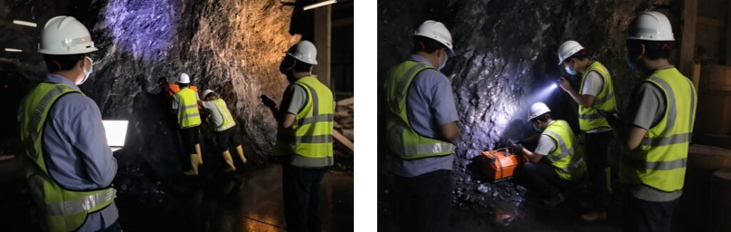
Image Analysis
Diversion Tunnel No. 1:
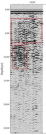
Description: The image shows the advance geological prediction results for Diversion Tunnel No. 1, with the survey line running from left to right when facing the tunnel face. The GPR image reveals strong radar reflection signals in the 2–7 m range, suggesting that the rock mass in this zone is relatively fractured. In the left half of the tunnel face, at a depth of 7.5–12.5 m, strong reflection signals are also observed, indicating that the rock mass in this zone may be fractured or contain fissures.
Diversion Tunnel No. 2:
Description: The image shows the advance geological prediction results for Diversion Tunnel No. 1, with the survey line running from left to right when facing the tunnel face. The GPR image reveals strong radar reflection signals in the 2–7 m range, suggesting that the rock mass in this zone is relatively fractured. In the left half of the tunnel face, at a depth of 7.5–12.5 m, strong reflection signals are also observed, indicating that the rock mass in this zone may be fractured or contain fissures.
FAQ
In gravity exploration (SI), what is the unit of gravity? How to convert gravity units between SI and CGS?
① In SI, it is m·s-2, and one percent of it is the international unit abbreviation g.u.;
② Conversion between SI and CGS: 1g.u.=10-1 mGal
What are gravitational field and gravitational potential?
Gravitational field: The space around the earth with gravity is called the gravitational field.
Gravitational potential: The gravitational potential W in the gravitational field is equal to the work done by a particle of unit mass moving from infinity to that point.
What is the normal gravity field of the earth? What are the rules for the change of the normal gravity field with latitude and altitude?
① The normal gravity field of the earth: Assuming that the earth is a rotating ellipsoid (reference plane), the surface is glossy, the internal density is uniform, or it is distributed in concentric layers, the density of each layer is uniform, and the deviation of the shape of the ellipsoid from the geoid is very small, then the gravity field generated by the earth is the normal gravity field.
② The normal gravity value is only related to the latitude, the smallest at the equator and the largest at the poles, with a difference of about 50,000 g.u.; the rate of change of the normal gravity value with latitude is the largest at 45° latitude, and zero at the equator and the poles; the normal gravity value decreases with increasing altitude, and its rate of change is -3.086 g.u.. The main feature of the long-term change is the "westward drift" of the geomagnetic elements, both the dipole field and the non-dipole field drift westward, and have a global nature.
What is the relationship between gravitational field strength and gravitational acceleration?
The gravitational field strength is equal to the gravitational acceleration in both numerical and dimensional terms, and the two are in the same direction. In gravity exploration, all references to gravity refer to gravitational acceleration. The gravitational field strength at a point in space is equal to the gravitational acceleration at that point.
What is gravity exploration?
Gravity exploration is an exploration method that is based on the density difference of rocks and ores. Since density difference will cause local changes in the normal gravity field of the earth (i.e. gravity anomaly), it is used to solve geological problems by observing and studying gravity anomalies.