Welcome to Geotech!



GEO-GPR-200 MHz Single-Frequency Geophysical Radar Series | 200MHz Shielded
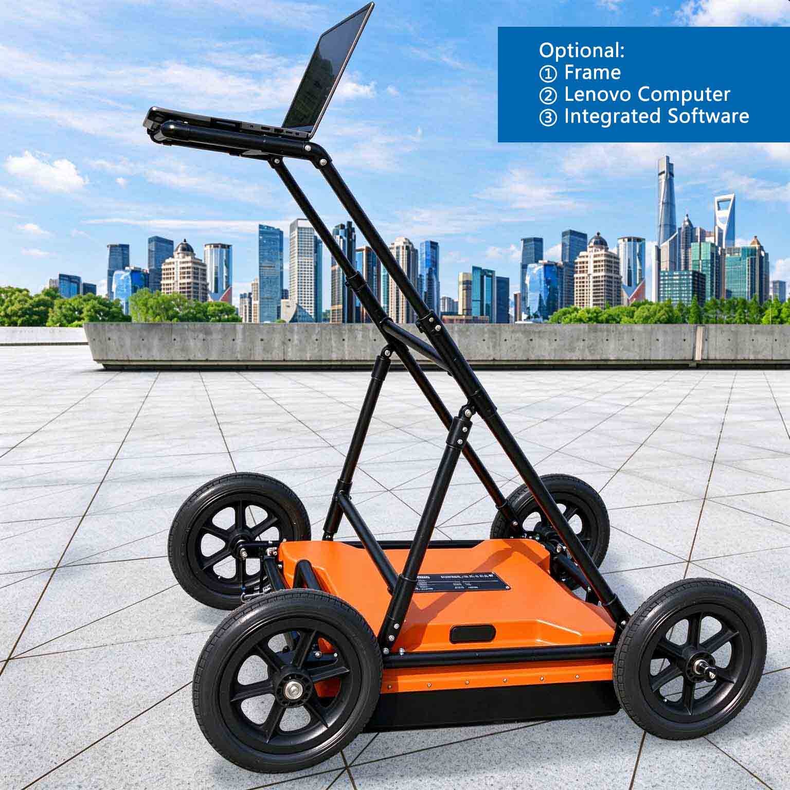
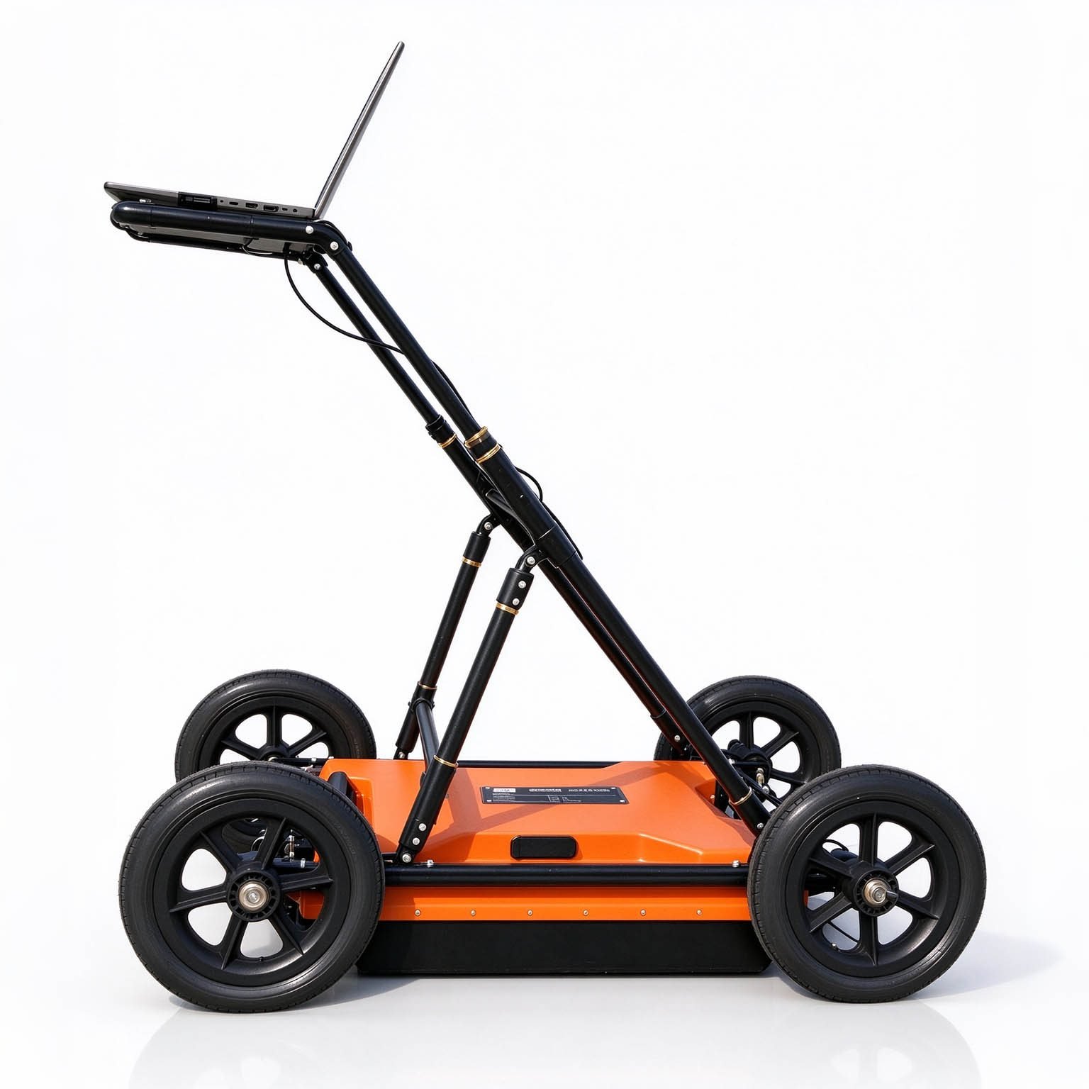
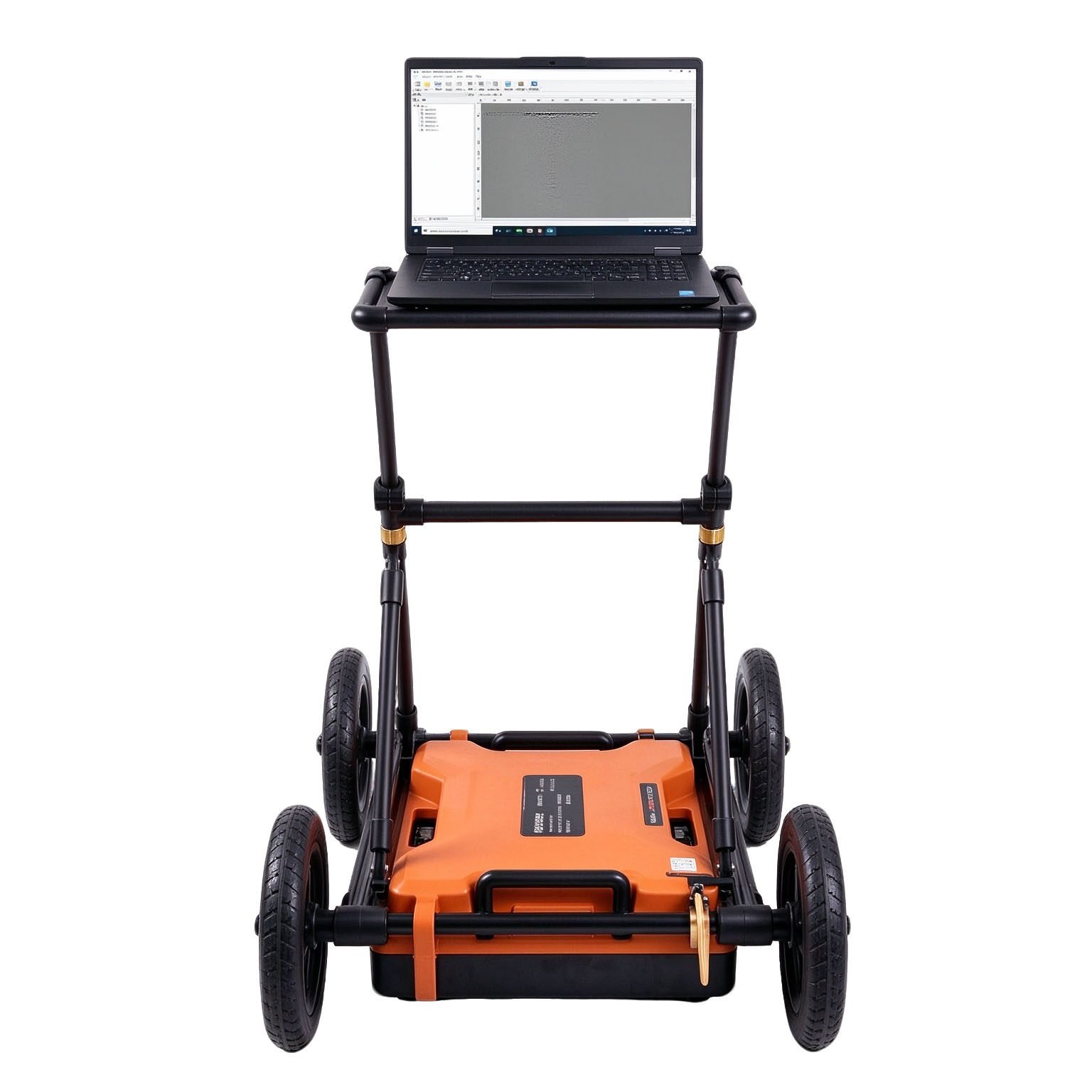

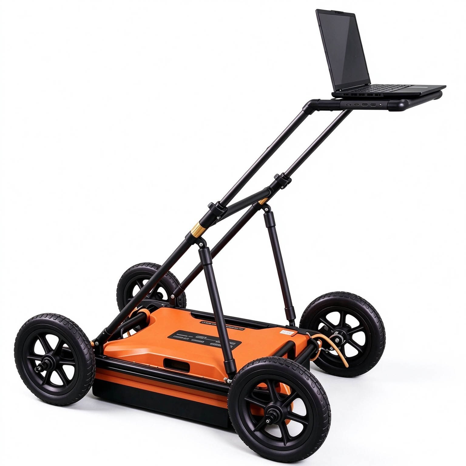





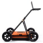


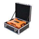



PRODUCT PARAMETERS
Description
 Abstract
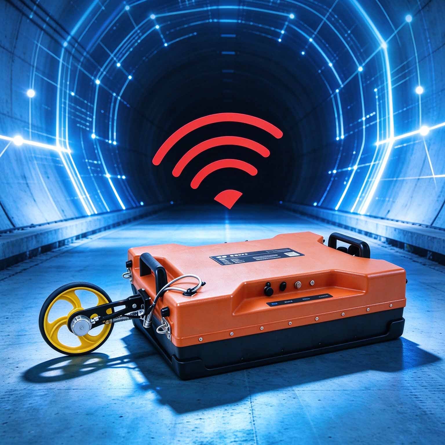
The GEO-GPR-200MHz sits at the crossover point of the GEO-GPR series: enough carrier frequency to trace buried pipes, cables and layer boundaries with clarity, and enough wavelength still to see several metres into the ground. It is the standard choice for pipeline survey, road subgrade inspection and dam investigation, where a 400 MHz antenna stops too early and a 100 MHz antenna cannot separate adjacent targets.
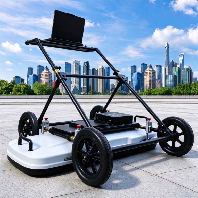
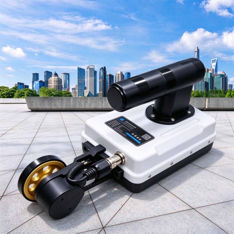
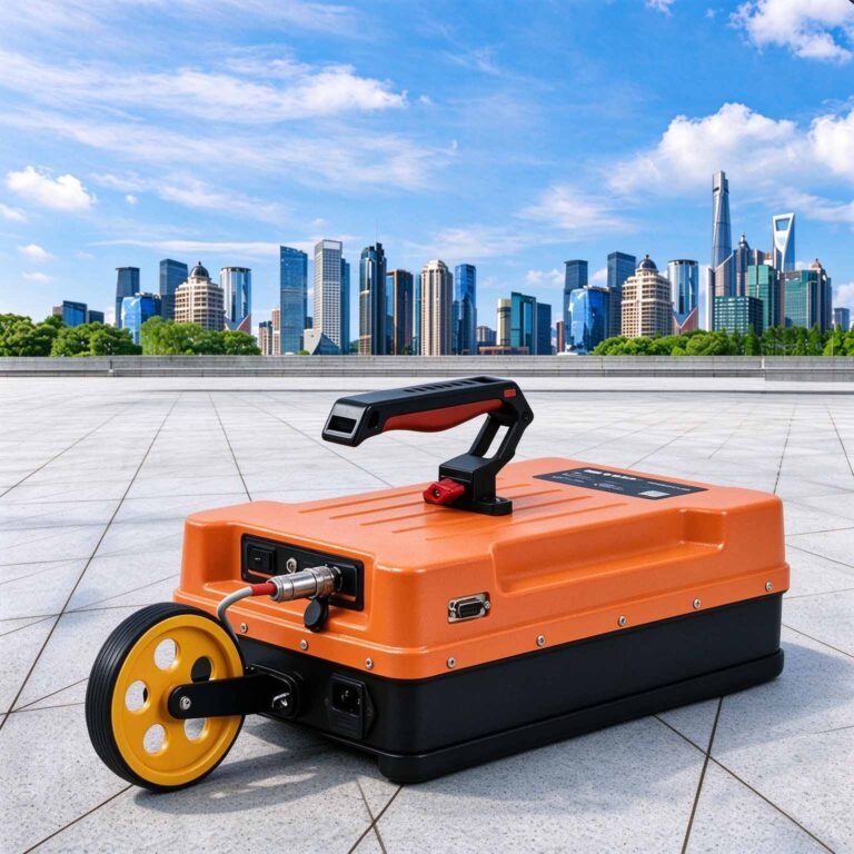
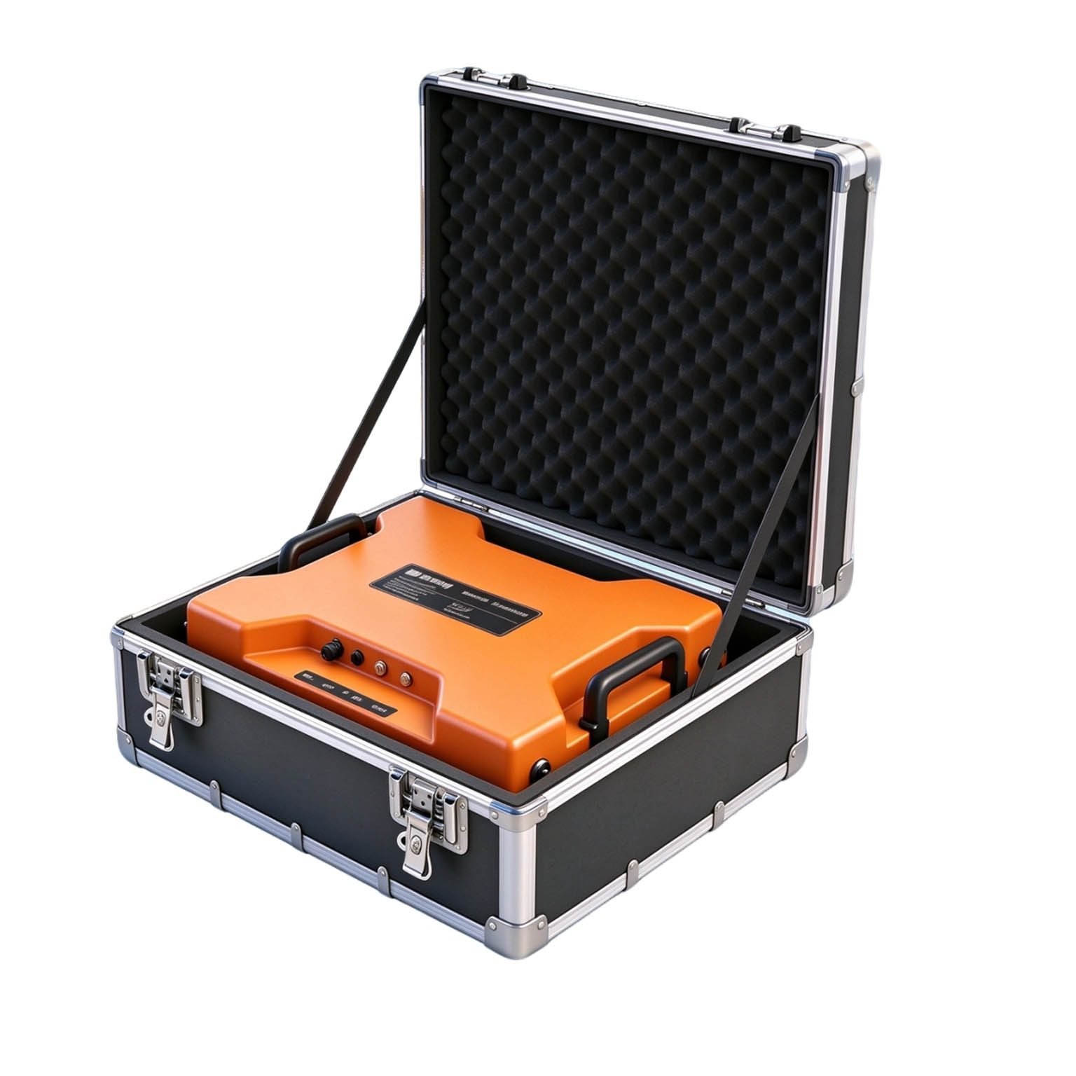
Like the rest of the range, the 200 MHz unit is a monostatic shielded antenna — transmitter, receiver and battery live inside the radome, and the profile returns to the tablet over a wireless link. No mainframe to strap down, no cable to trip over, and no separate power lead to keep out of a wet trench.
Technical Highlights
- Depth without giving up separation. At 200 MHz the quarter-wavelength resolution cell is roughly 13 cm in sound rock, so two buried services a metre apart read as two hyperbolas, not one smear.
- Shielded enough for urban ground. The Faraday shield suppresses the coupling that makes low-frequency surveys unreadable near substations, street lighting and rebar mats — the reason a 200 MHz horn struggles in a city while this unit works.
- Balanced survey productivity. 350 traces per second with a distance-trigger keeps a walking crew recording continuously, and the 8 m depth ceiling covers the majority of buried-service and subgrade investigation in a single pass.
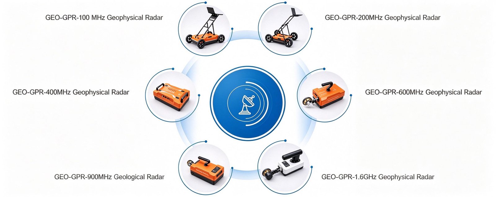
- Same receiver, whole series. Move between 200 MHz and the other five GEO-GPR antennas on one platform, so a contractor can take utility jobs in the morning and a deeper geological line in the afternoon.
Features
- Integrated host-and-antenna construction — the instrument is the antenna
- Internal lithium pack rated at ≥8 h of continuous logging
- Three-proof sealed housing for trench, roadside and embankment work
- Wireless link beyond 50 m; Ethernet available for fixed rigs
- Point, distance-trigger, continuous and GNSS-triggered acquisition
- Live pseudo-colour, stacked-waveform and grayscale imaging on the control panel
- On-screen gain, band-pass and Dewow filtering while the line is still being walked
- Automatic pseudosection assembly for long continuous profiles
- Interchangeable with GEO-GPR 100 / 400 / 600 / 900 MHz and 1.6 GHz antennas
Applications

| Application | What the 200 MHz antenna delivers | Typical depth |
| Buried service location | Metallic and non-metallic pipes and ducts at separation distances a lower frequency would blur | 1–8 m |
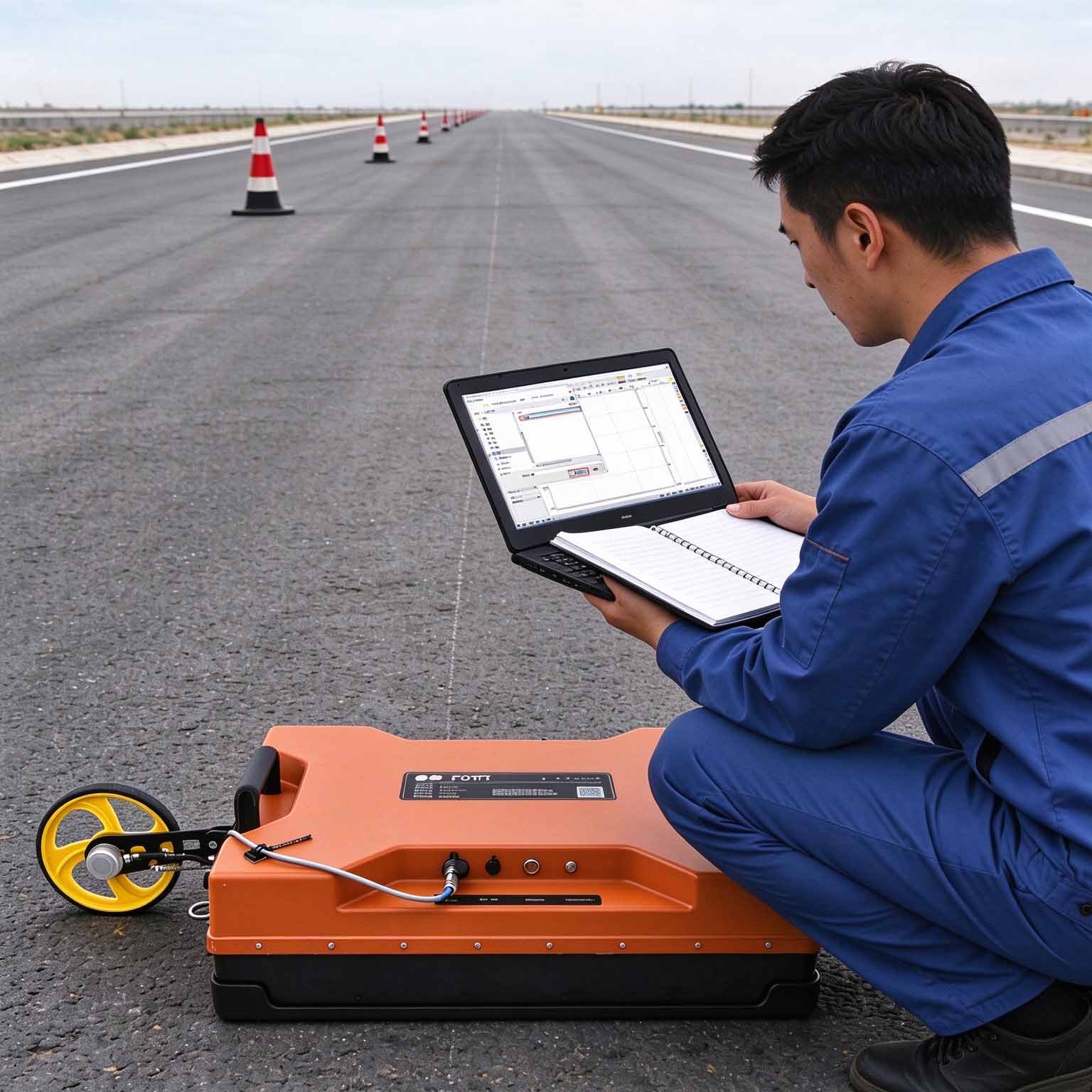
| Road and airfield subgrade | Layer boundaries, subgrade deterioration, moisture accumulation beneath the pavement | 1–6 m |
| Dam and embankment investigation | Solution voids, loose zones and seepage paths within and beneath the fill | 2–8 m |
| Karst and cavity screening | Medium-depth sinkholes and collapse features ahead of foundation works | 2–8 m |
| Tunnel lining behind the invert | Back-void and loosened ground beyond the installed support | 2–6 m |
| Archaeological and site-wide mapping | Trench fills, walls, pits and stratigraphic change over large areas at walking pace | 0.5–4 m |
Typical Performance Reference
Vertical resolution taken as approximately λ/4, with λ = c / (f · √εr). Depth bands are engineering guidance, not guarantees — confirm against a site trial where depth is the controlling requirement.
| Medium | εr | Wave velocity | Reference depth band | Vertical resolution |
| Dry sand, gravel, asphalt | 4 | 0.150 m/ns | 5–8 m | ≈19 cm |
| Moist soil, general overburden | 6 | 0.122 m/ns | 4–8 m | ≈15 cm |
| Sound limestone, concrete | 9 | 0.100 m/ns | 2–5 m | ≈13 cm |
| Wet clay, basalt | 16 | 0.075 m/ns | 1–3 m | ≈9 cm |
| Saturated fine-grained soil | 25 | 0.060 m/ns | 0.5–2 m | ≈8 cm |
Specifications
| Parameter | Specification |
| Antenna type | Monostatic shielded antenna |
| Centre frequency | 200 MHz |
| Scan rate | 350 traces/s |
| A/D conversion | 18 / 32 bit |
| Signal-to-noise ratio | Better than 160 dB |
| Maximum detection depth | 8 m |
| Acquisition modes | Point-by-point, distance-triggered, continuous |
| Display modes | Pseudo-colour, stacked waveform, grayscale |
| Continuous operating time | ≥8 h |
| Wireless data range | >50 m |
| Operating voltage | 10–15 V DC |
| Operating temperature | −30 °C to +70 °C |
| Unit weight | 20.75 kg |
| Series compatibility | Full GEO-GPR antenna family, 100 MHz to 1.6 GHz |
Full technical documentation and demonstration data available on request.
 Options & Accessories
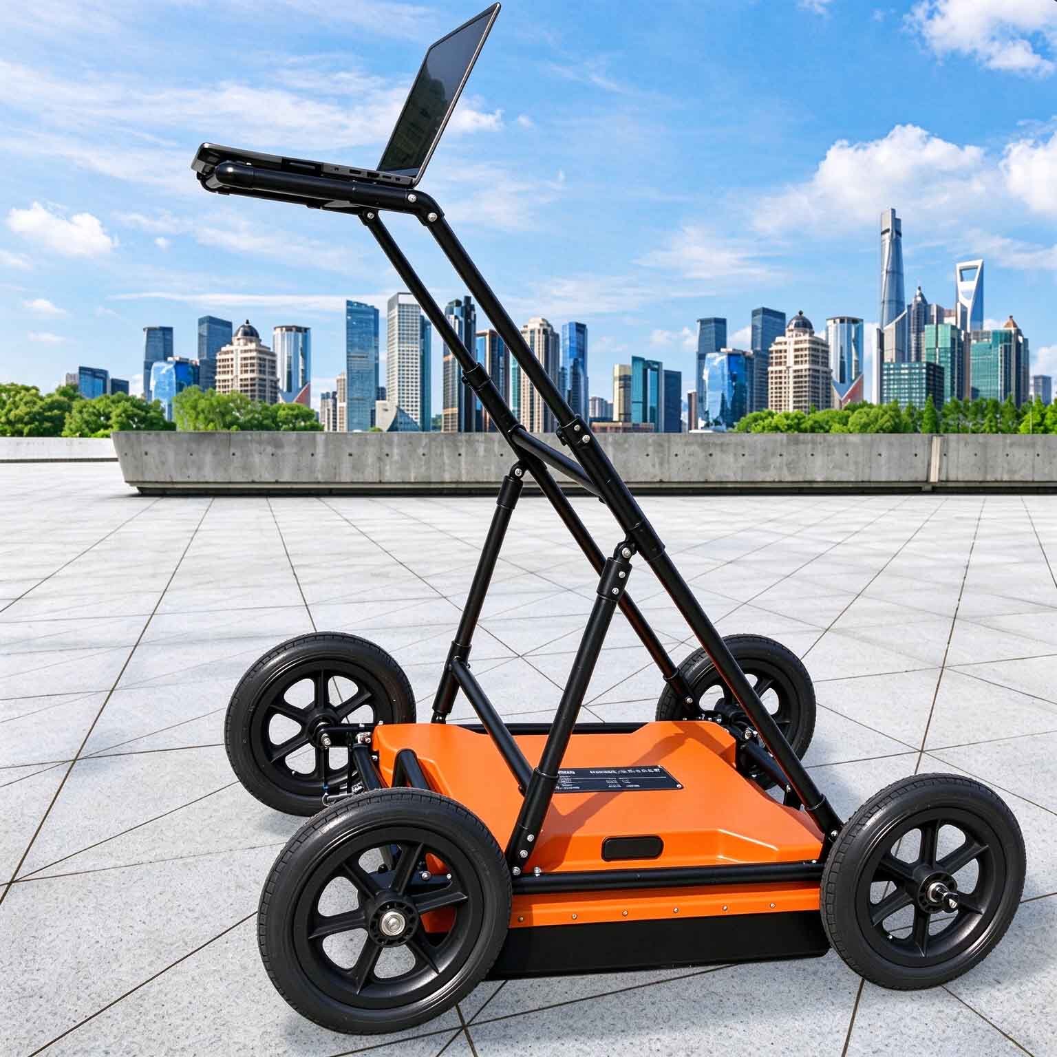
- Vehicle-deck, hand-cart, tunnel-trolley and rail-carriage mounting frames
- High-accuracy GNSS positioning for coordinate-logged survey lines
- Data processing and 2D/3D inversion software package
- Interchangeable GEO-GPR antennas from 100 MHz to 1.6 GHz
- Extended-range battery pack for multi-shift deployments
FAQ
In gravity exploration (SI), what is the unit of gravity? How to convert gravity units between SI and CGS?
① In SI, it is m·s-2, and one percent of it is the international unit abbreviation g.u.;
② Conversion between SI and CGS: 1g.u.=10-1 mGal
What are gravitational field and gravitational potential?
Gravitational field: The space around the earth with gravity is called the gravitational field.
Gravitational potential: The gravitational potential W in the gravitational field is equal to the work done by a particle of unit mass moving from infinity to that point.
What is the normal gravity field of the earth? What are the rules for the change of the normal gravity field with latitude and altitude?
① The normal gravity field of the earth: Assuming that the earth is a rotating ellipsoid (reference plane), the surface is glossy, the internal density is uniform, or it is distributed in concentric layers, the density of each layer is uniform, and the deviation of the shape of the ellipsoid from the geoid is very small, then the gravity field generated by the earth is the normal gravity field.
② The normal gravity value is only related to the latitude, the smallest at the equator and the largest at the poles, with a difference of about 50,000 g.u.; the rate of change of the normal gravity value with latitude is the largest at 45° latitude, and zero at the equator and the poles; the normal gravity value decreases with increasing altitude, and its rate of change is -3.086 g.u.. The main feature of the long-term change is the "westward drift" of the geomagnetic elements, both the dipole field and the non-dipole field drift westward, and have a global nature.
What is the relationship between gravitational field strength and gravitational acceleration?
The gravitational field strength is equal to the gravitational acceleration in both numerical and dimensional terms, and the two are in the same direction. In gravity exploration, all references to gravity refer to gravitational acceleration. The gravitational field strength at a point in space is equal to the gravitational acceleration at that point.
What is gravity exploration?
Gravity exploration is an exploration method that is based on the density difference of rocks and ores. Since density difference will cause local changes in the normal gravity field of the earth (i.e. gravity anomaly), it is used to solve geological problems by observing and studying gravity anomalies.