Welcome to Geotech!



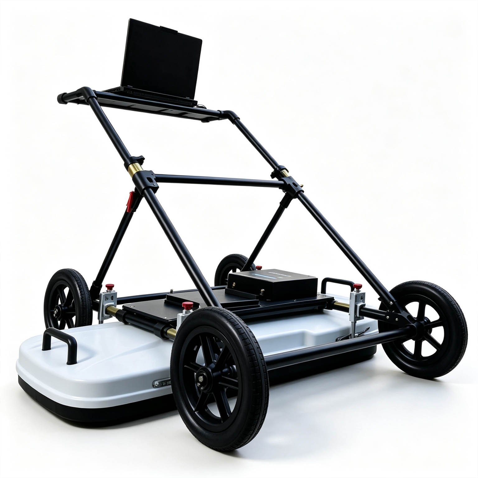
Push‑Type Multi‑Channel 3D Ground Penetrating Radar丨GEO‑GPR‑3D‑P



PRODUCT PARAMETERS
Description
 Abstract
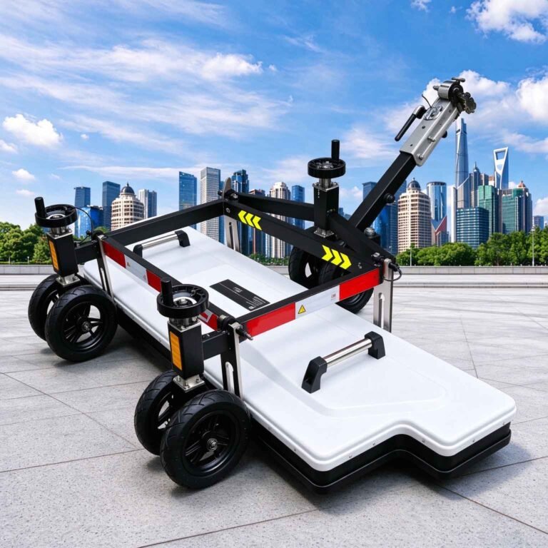
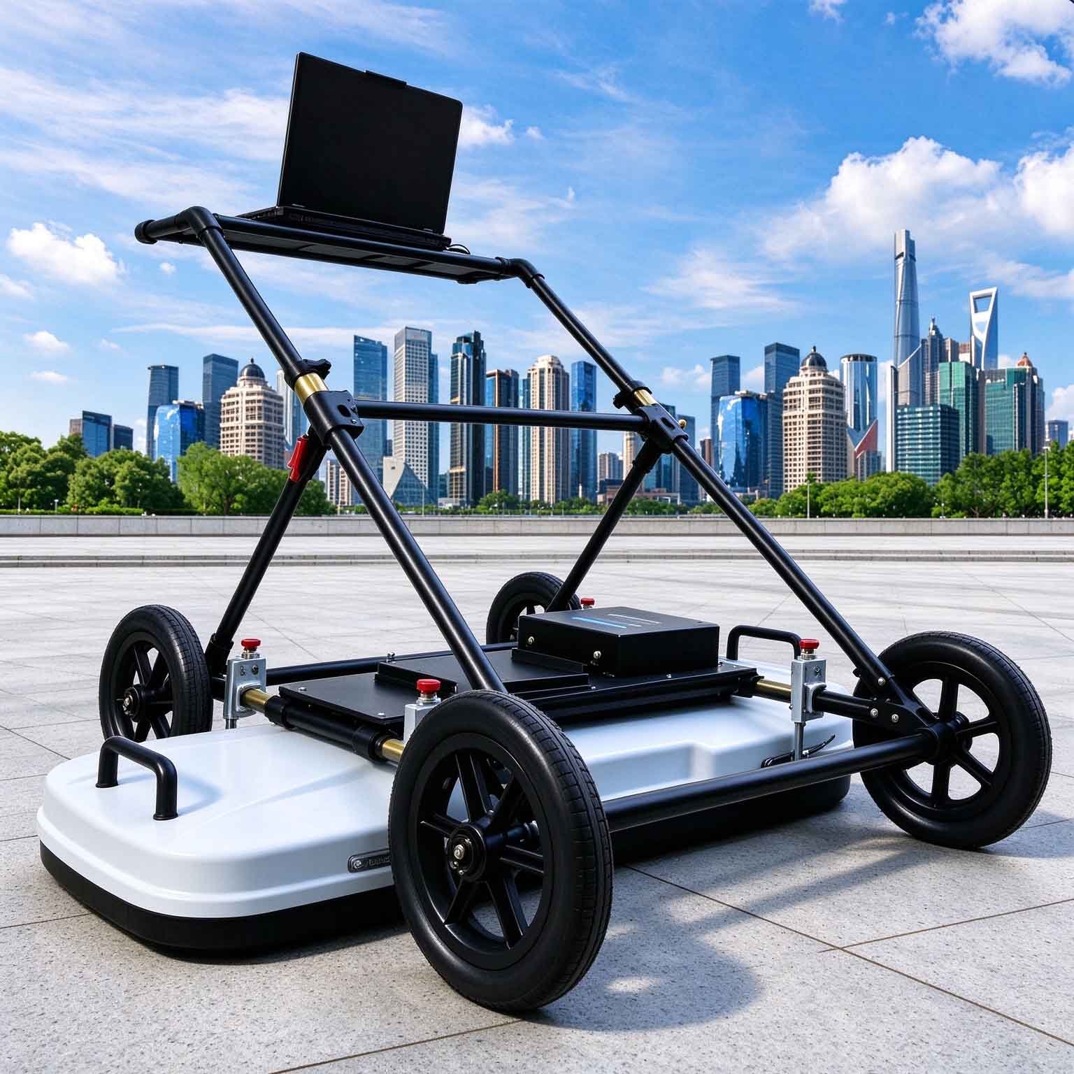
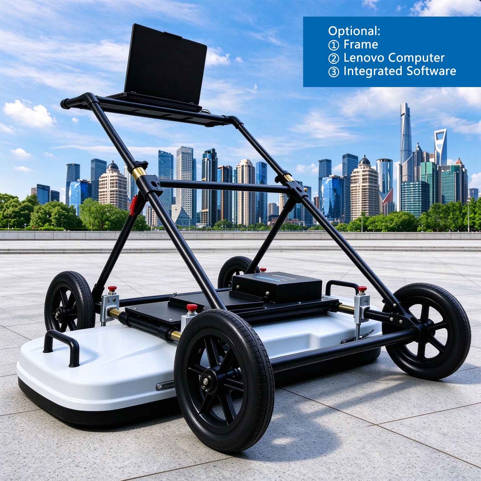
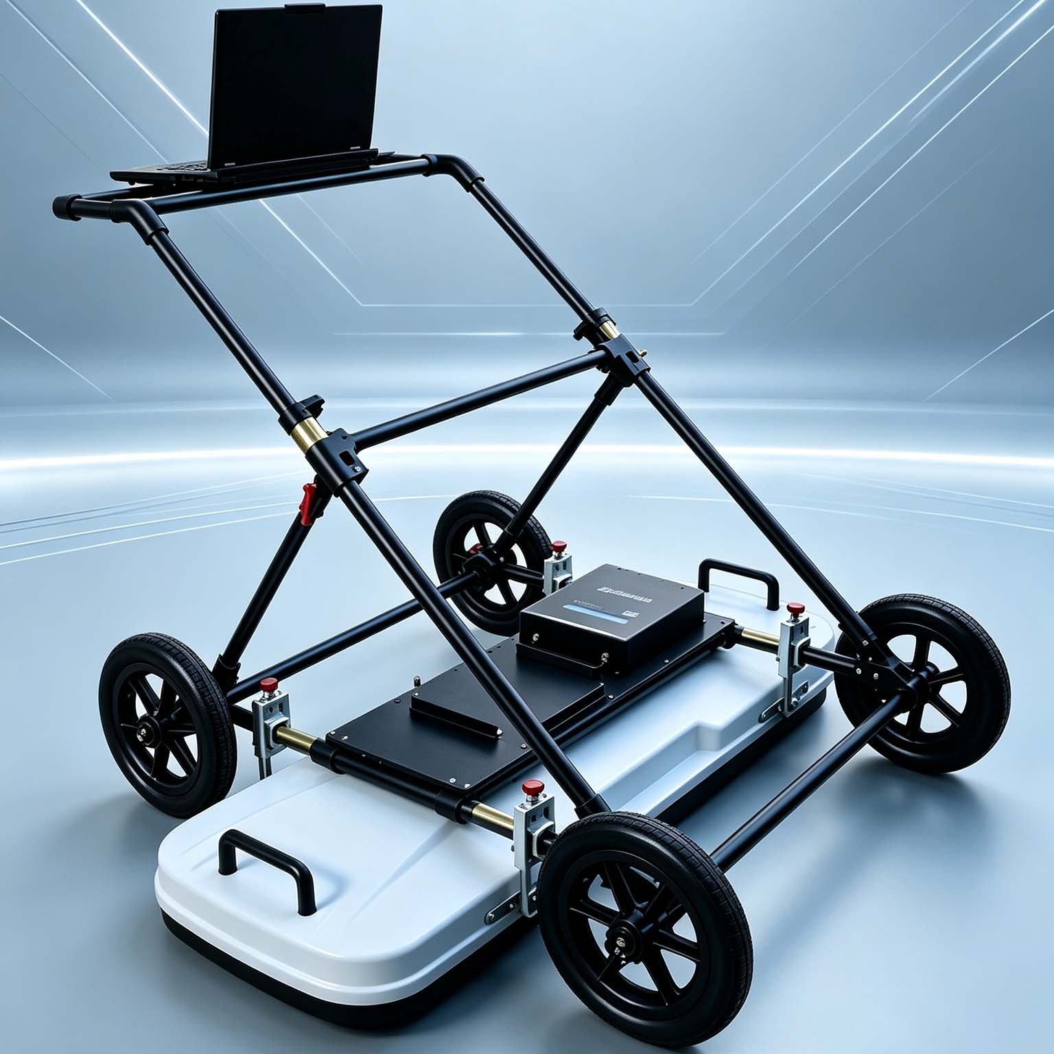
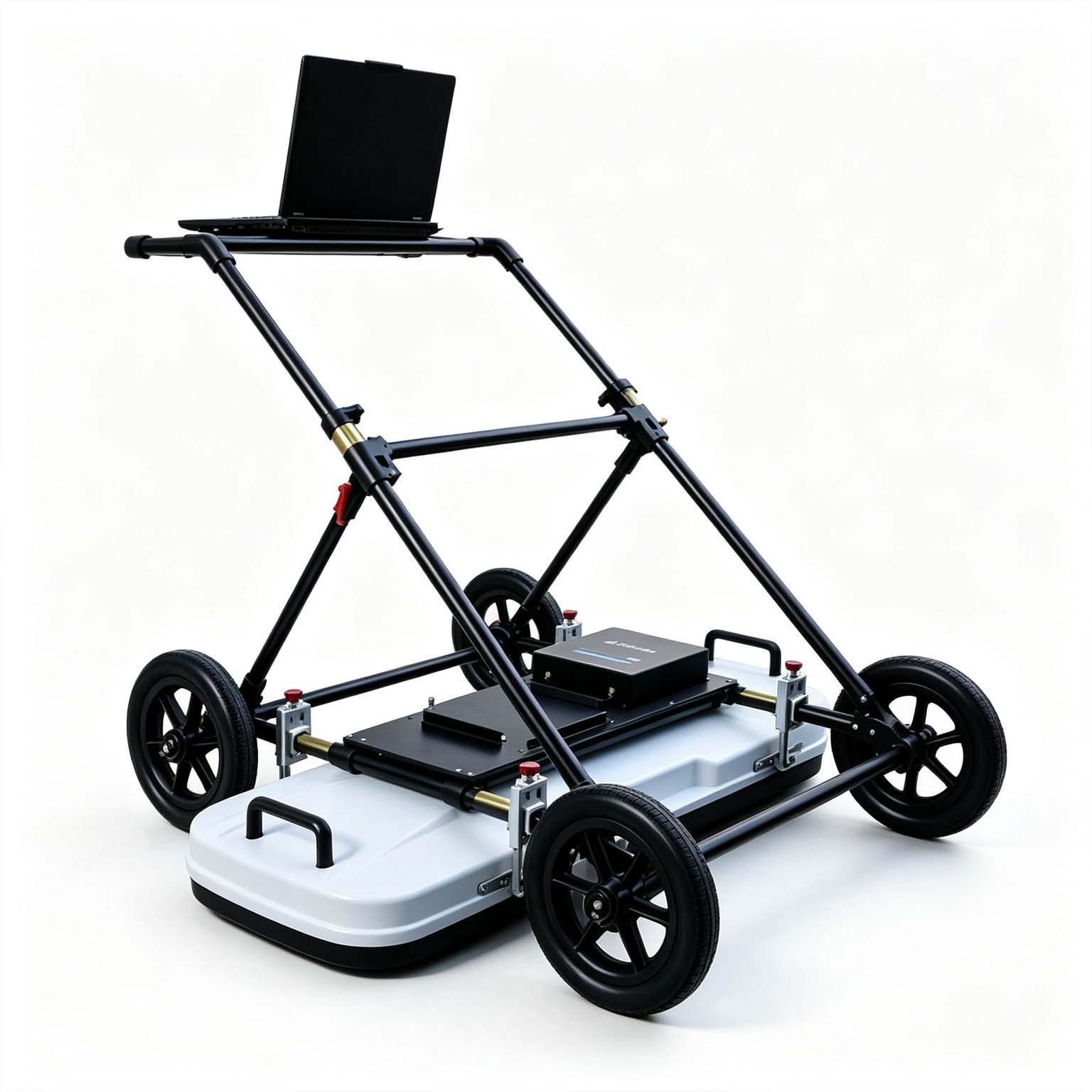
The GEO-GPR-3D is a push-type multi-channel 3D ground penetrating radar array that builds a volumetric subsurface model from a single walk-behind pass. Its 1.4 m-wide antenna carries up to 64 channels, giving a lateral channel spacing of about 2.2 cm — dense enough that three orthogonal section sets can be combined into one 3D model without the aliasing that coarser arrays produce.
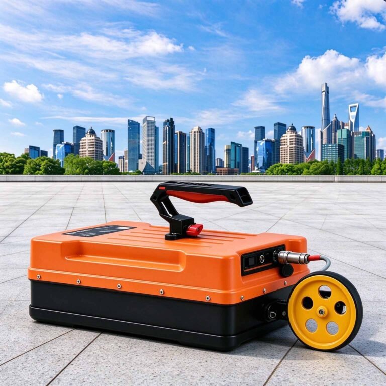
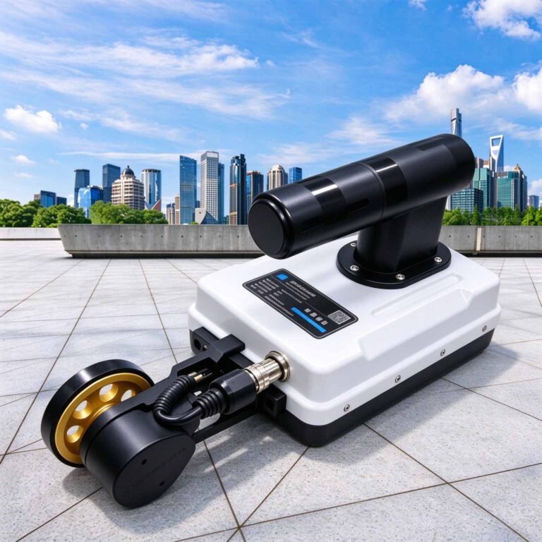
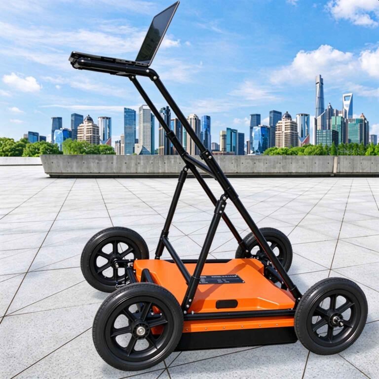
At 29 kg in total, the GEO-GPR-3D is pushed by one operator into spaces where towed 3D arrays cannot work: sidewalks, alleyways, bridge maintenance walkways, levee crests, airport aprons and congested urban streets. Transmitter, receivers and processing sit inside the frame; the survey line runs back to the control unit over a single cable.
Technical Highlights
- Volumetric imaging in one pass. Simultaneous multi-channel acquisition produces sections in three directions, which are assembled into a 3D model rather than interpreted line by line.
- 64 channels across 1.4 m. Lateral sampling of roughly 2.2 cm meets the density required for void and service detection at road-survey depth, and holds that density across a full lane-width swath instead of a narrow strip.
- Lightest array per channel in its class. A 24-channel towed 3D array on the market weighs around 54 kg. The GEO-GPR-3D reaches 64 channels in a 29 kg walk-behind frame, which is what makes confined-space 3D survey physically possible.
- Polarisation matched to the target. Horizontal-horizontal (HH) response maximises reflection from pipes, conduits and bars running across the line; vertical and cross-polarisation options are configurable for layer and stratigraphic work.
Features
- 8 to 64 selectable channels, paired with 0–1.4 m swath width
- Ultra-wideband imaging for high-resolution reflection detail
- One-click configuration with automatic acquisition parameter setting
- RTK positioning with BeiDou and GPS support for coordinate-locked 3D models
- Push-type frame, 1320 × 520 × 180 mm, 16 kg unloaded / 29 kg total
- Works on surfaces where towed and vehicle-mounted arrays cannot be deployed
- Pseudo-colour, stacked-waveform and grayscale display with 3D visualisation
- Pavement layer and thickness identification across the surveyed swath
- Multi-polarisation configurations available on request
Applications

| Application | What the 3D array delivers | Reference depth |
| Road and airfield defect survey | Void, loosening and moisture anomalies located in three dimensions beneath the pavement | frequency-dependent |
| Urban utility and pipeline mapping | Service corridors modelled in 3D, with orientation resolved from polarisation response | frequency-dependent |
| Pavement layer thickness | Layer boundaries mapped continuously across the full swath instead of along a single line | 0.1–1 m |
| Structural and subsurface defect detection | Delamination, honeycombing and buried objects positioned in volume, not on a section | 0.1–1 m |
| Levee and dam burrow detection | Ant nests and animal burrows within the embankment identified as discrete 3D bodies | 0.2–2 m |
| Sidewalk, alley and confined-space survey | Full-width 3D coverage pushed by one operator where vehicles cannot enter | 0.2–2 m |
Depth is governed primarily by the ground’s conductivity and by the working frequency selected, not by channel count. The frequency-versus-depth table below is required reading before configuring a system — please request it with your ground conditions.
Configuration Guidance
Channel count and swath width must be selected together. A wide swath on a low channel count undersamples the lateral axis and will miss or distort small and shallow targets.
| Channels | Lateral spacing at 1.4 m swath | Suitability |
| 64 | ≈2.2 cm | Full 3D void, service and layer survey at code sampling density |
| 32 | ≈4.5 cm | Layer mapping and larger voids; reduced shallow-service detail |
| 16 | ≈9.3 cm | Regional stratigraphy; not recommended for void or service location |
| 8 | ≈20 cm | Use only with a correspondingly reduced swath |
Specifications
| Parameter | Specification |
| Instrument type | Push-type multi-channel 3D GPR array |
| Imaging method | Ultra-wideband, simultaneous multi-channel acquisition |
| Centre frequency | configurable (nominal 900 MHz); full operating band on request |
| Channels | 8 / 16 / 32 / 64, selected with swath width |
| Coverage width | up to 1.4 m per pass |
| Polarisation | HH standard; multi-polarisation configurable |
| Signal-to-noise ratio | better than 160 dB |
| A/D conversion | 18 bit |
| Positioning | RTK, BeiDou and GPS |
| Communication | wired connection to control unit |
| 3D output | sections in three directions combined into a volumetric model |
| Operating temperature | −30 °C to +70 °C |
| Weight | 16 kg unloaded / 29 kg total |
| Outline dimensions | 1320 × 520 × 180 mm |
Depth capability is stated per frequency band and per ground type on request. Full technical documentation, calibration records and a site demonstration are available.
FAQ
In gravity exploration (SI), what is the unit of gravity? How to convert gravity units between SI and CGS?
① In SI, it is m·s-2, and one percent of it is the international unit abbreviation g.u.;
② Conversion between SI and CGS: 1g.u.=10-1 mGal
What are gravitational field and gravitational potential?
Gravitational field: The space around the earth with gravity is called the gravitational field.
Gravitational potential: The gravitational potential W in the gravitational field is equal to the work done by a particle of unit mass moving from infinity to that point.
What is the normal gravity field of the earth? What are the rules for the change of the normal gravity field with latitude and altitude?
① The normal gravity field of the earth: Assuming that the earth is a rotating ellipsoid (reference plane), the surface is glossy, the internal density is uniform, or it is distributed in concentric layers, the density of each layer is uniform, and the deviation of the shape of the ellipsoid from the geoid is very small, then the gravity field generated by the earth is the normal gravity field.
② The normal gravity value is only related to the latitude, the smallest at the equator and the largest at the poles, with a difference of about 50,000 g.u.; the rate of change of the normal gravity value with latitude is the largest at 45° latitude, and zero at the equator and the poles; the normal gravity value decreases with increasing altitude, and its rate of change is -3.086 g.u.. The main feature of the long-term change is the "westward drift" of the geomagnetic elements, both the dipole field and the non-dipole field drift westward, and have a global nature.
What is the relationship between gravitational field strength and gravitational acceleration?
The gravitational field strength is equal to the gravitational acceleration in both numerical and dimensional terms, and the two are in the same direction. In gravity exploration, all references to gravity refer to gravitational acceleration. The gravitational field strength at a point in space is equal to the gravitational acceleration at that point.
What is gravity exploration?
Gravity exploration is an exploration method that is based on the density difference of rocks and ores. Since density difference will cause local changes in the normal gravity field of the earth (i.e. gravity anomaly), it is used to solve geological problems by observing and studying gravity anomalies.