Welcome to Geotech!



GEO-GPR-600 MHz Single-Frequency Geophysical Radar Series | 600MHz









PRODUCT PARAMETERS
Description
 Abstract
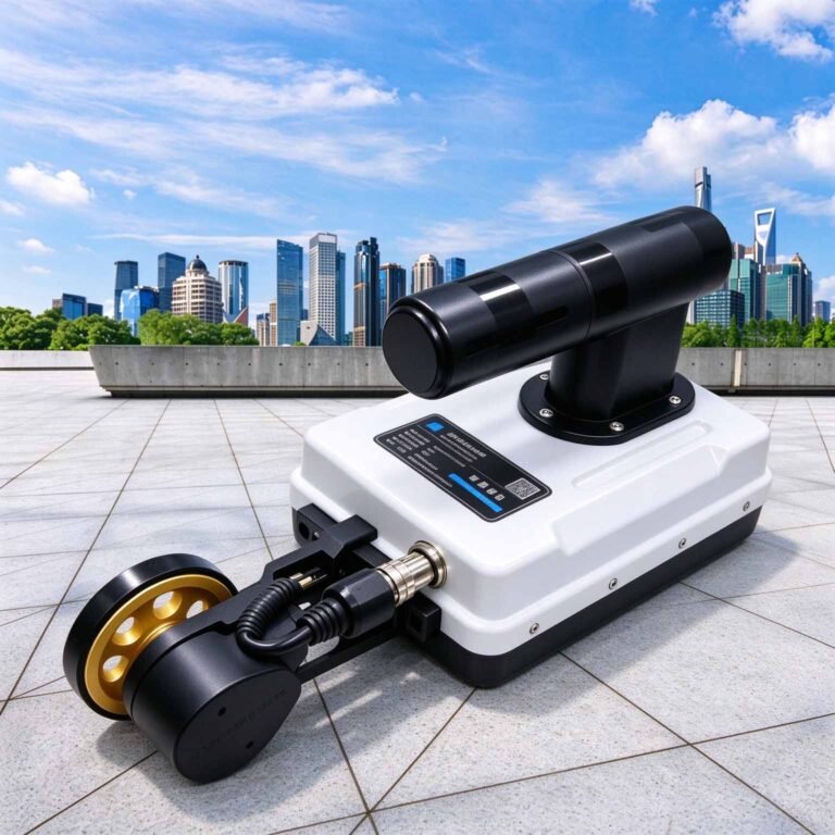
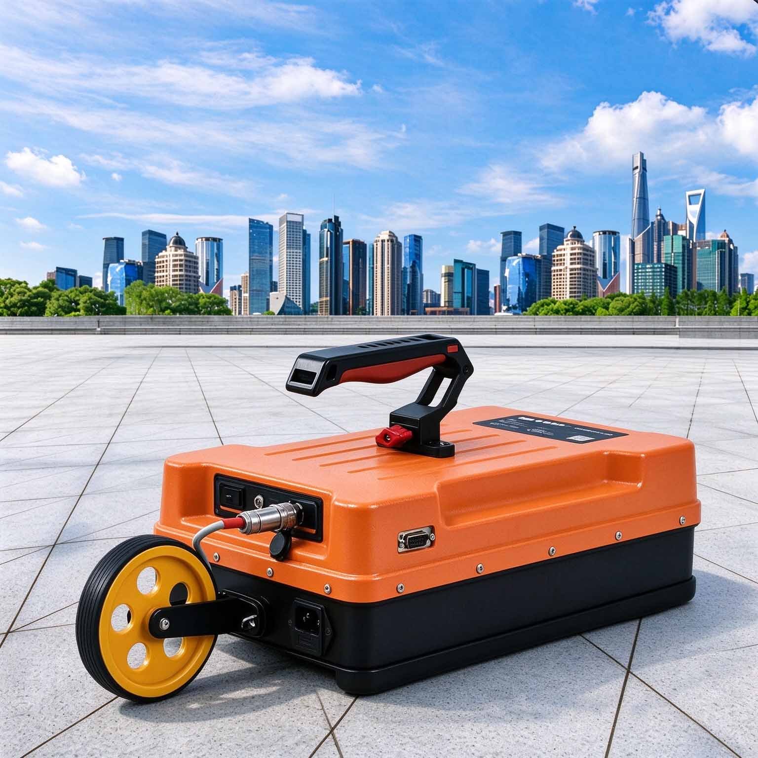
The GEO-GPR-600MHz is built for the structural end of the range: measuring cover depth, mapping rebar and tendon layout, and grading a bridge deck down to the top of the mat. Its wavelength is short enough that a bar at 50 mm cover produces a clean, measurable diffraction, yet it still penetrates far enough to check the lower mat and the deck substrate.
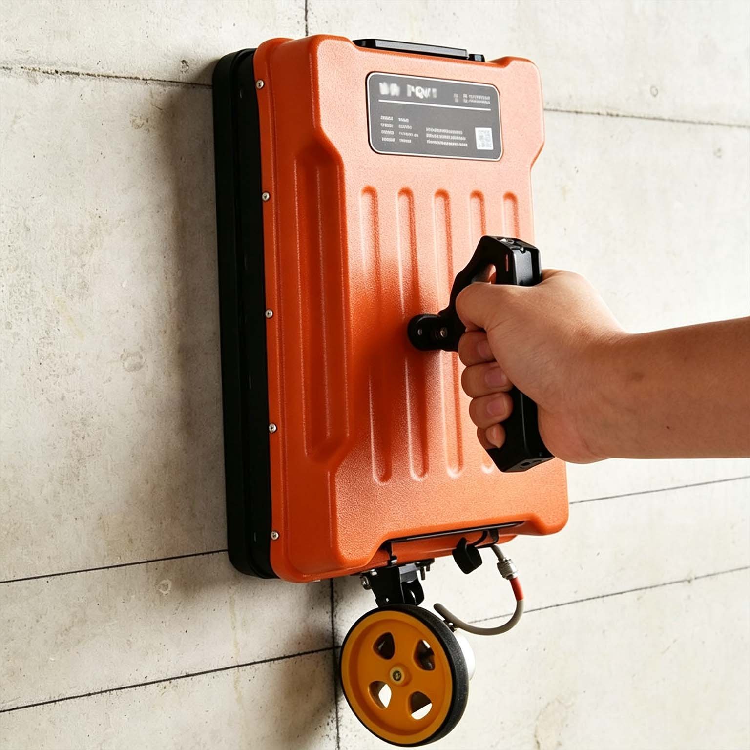
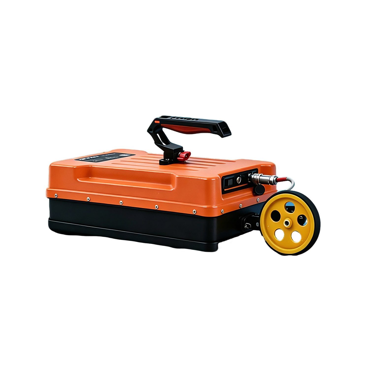
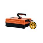
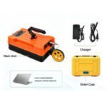
At 3.35 kg the unit is a one-hand push across a deck or a floor slab, with the antenna, electronics and battery in one sealed shell and the profile streaming wirelessly to the panel in the operator’s other hand.
Technical Highlights
- Cover measurement you can sign off. Around 4 cm quarter-wavelength resolution in concrete separates adjacent bars, so spacing, diameter and cover come from the record itself rather than from a destructive break-out.
- Two mats in one pass. Where 900 MHz stops at the top layer, the 600 MHz antenna still reaches the lower mat and the substrate beneath a deck, which is what a bridge condition survey actually needs.
- Shielded over live structures. Rebar mats, truss steel, site radios and temporary supplies all couple straight into an unshielded antenna; the monostatic shield keeps the record interpretable on a congested deck.
- Deck-scale throughput. 350 traces per second with distance triggering means a lane closes for one pass, not a grid walk, and the pseudosection is assembled as you go.
Features
- 3.35 kg shielded monostatic antenna — single-operator deck survey
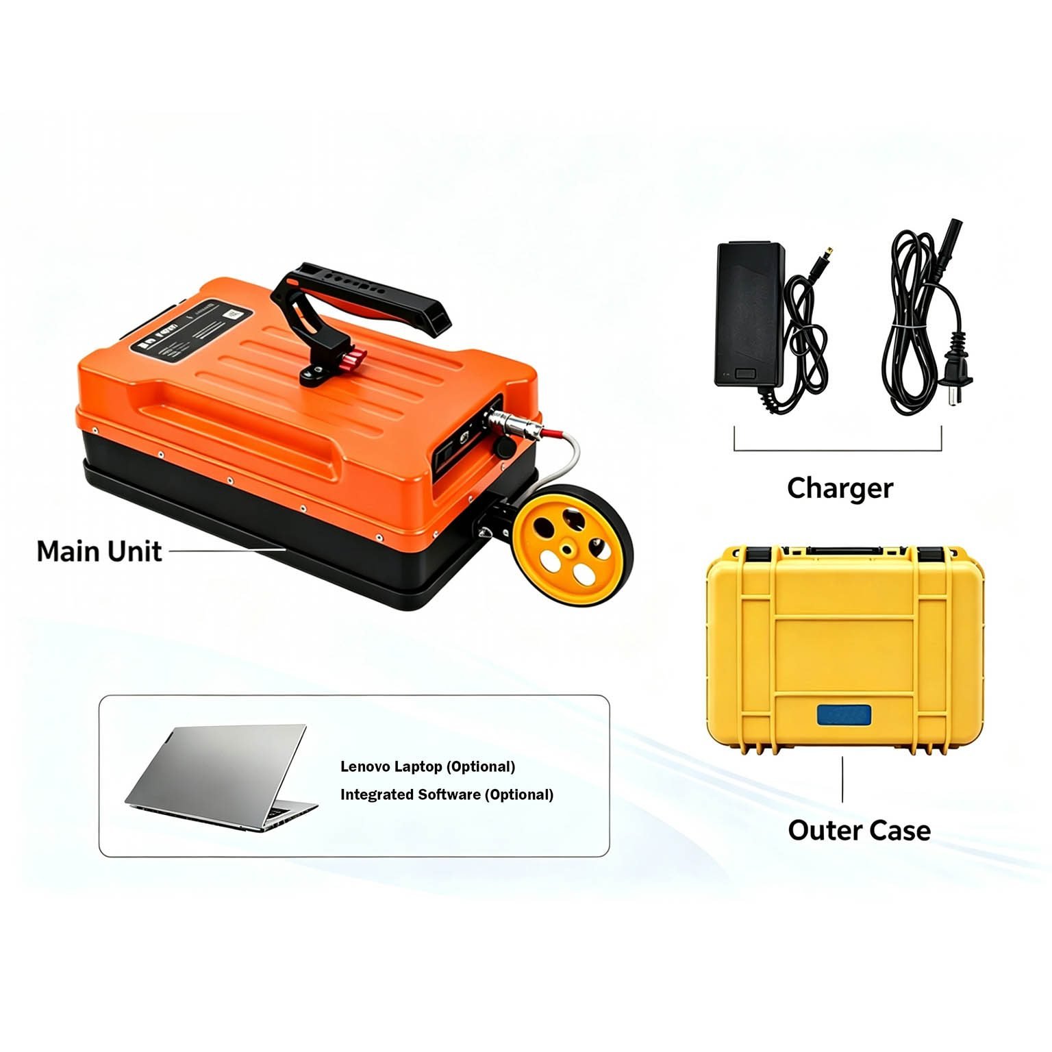
- Transmitter, receiver, battery and wireless radio integrated in one housing
- ≥8 h continuous logging on the internal pack
- Point, distance-trigger, continuous and GNSS-triggered acquisition
- Real-time pseudo-colour and grayscale imaging with stacked waveform view
- On-screen Dewow, band-pass and depth-gain control during acquisition
- Chainage-locked export for post-survey condition grading
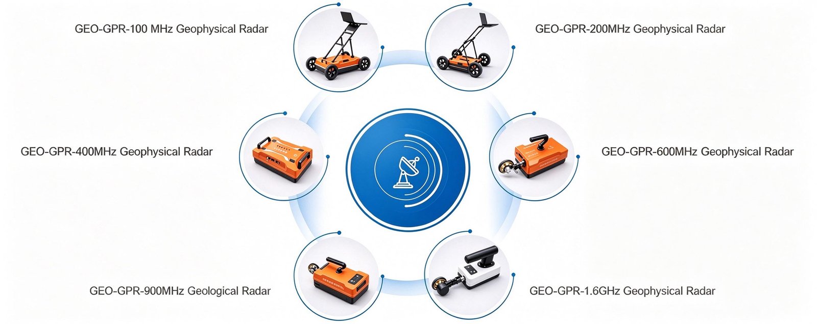
- Accepts every GEO-GPR antenna from 100 MHz to 1.6 GHz on the same platform
Applications

| Application | What the 600 MHz antenna delivers | Typical depth |
| Rebar and tendon mapping | Bar position, spacing, diameter estimate and cover depth in slabs and beams | 0.02–0.4 m |
| Bridge deck condition survey | Cover, delamination zone, lower mat and deck substrate | 0.05–1.5 m |
| Concrete cover verification | As-built cover against design for acceptance and repair scoping | 0.02–0.15 m |
| Pavement layer thickness | Thin surfacing and base layer boundaries on roads and aprons | 0.05–1 m |
| Shallow void and delamination | Air pockets between layers and beneath tiles or screeds | 0.03–0.8 m |
| Post-tension duct tracing | Duct layout and grouting voids within a slab or segment | 0.05–0.6 m |
Typical Performance Reference
Vertical resolution ≈ λ/4, λ = c / (f · √εr). Depth bands are engineering guidance; for acceptance work confirm on the structure itself.
| Medium | εr | Wave velocity | Reference depth band | Vertical resolution |
| Dry sand, gravel, asphalt | 4 | 0.150 m/ns | 1.5–3 m | ≈6 cm |
| Moist soil, general overburden | 6 | 0.122 m/ns | 1–3 m | ≈5 cm |
| Sound limestone, concrete | 9 | 0.100 m/ns | 0.8–2 m | ≈4 cm |
| Wet clay, basalt | 16 | 0.075 m/ns | 0.5–1.5 m | ≈3 cm |
| Saturated fine-grained soil | 25 | 0.060 m/ns | 0.3–1 m | ≈2.5 cm |
Specifications
| Parameter | Specification |
| Antenna type | Monostatic shielded antenna |
| Centre frequency | 600 MHz |
| Scan rate | 350 traces/s |
| A/D conversion | 18 / 32 bit |
| Signal-to-noise ratio | Better than 160 dB |
| Maximum detection depth | 2 m |
| Acquisition modes | Point-by-point, distance-triggered, continuous |
| Display modes | Pseudo-colour, stacked waveform, grayscale |
| Continuous operating time | ≥8 h |
| Wireless data range | >50 m |
| Operating voltage | 10–15 V DC |
| Operating temperature | −30 °C to +70 °C |
| Unit weight | 3.35 kg |
| Series compatibility | Full GEO-GPR antenna family, 100 MHz to 1.6 GHz |
Full technical documentation and demonstration data available on request.
 Options & Accessories
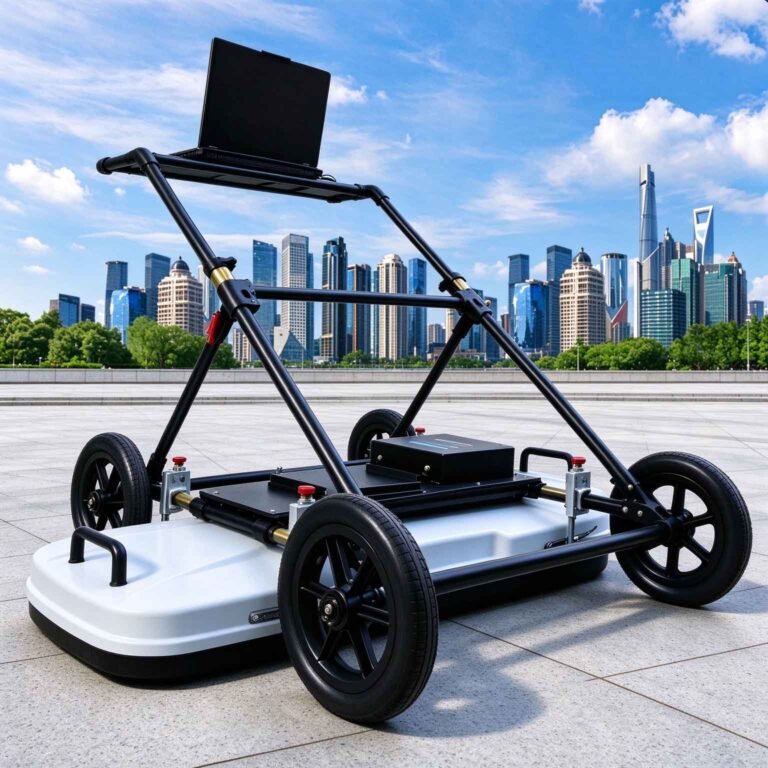
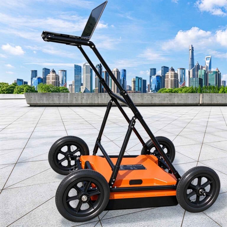
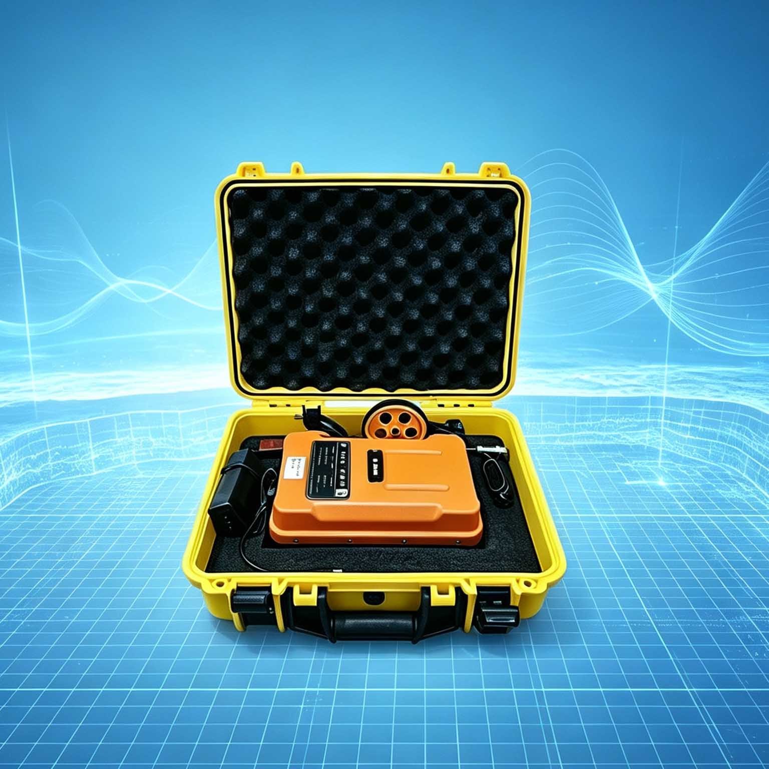
- Vehicle-deck, hand-cart, tunnel-trolley and rail-carriage mounting frames
- High-accuracy GNSS positioning for coordinate-logged survey lines
- Data processing and 2D/3D inversion software package
- Interchangeable GEO-GPR antennas from 100 MHz to 1.6 GHz
- Extended-range battery pack for multi-shift deployments
FAQ
In gravity exploration (SI), what is the unit of gravity? How to convert gravity units between SI and CGS?
① In SI, it is m·s-2, and one percent of it is the international unit abbreviation g.u.;
② Conversion between SI and CGS: 1g.u.=10-1 mGal
What are gravitational field and gravitational potential?
Gravitational field: The space around the earth with gravity is called the gravitational field.
Gravitational potential: The gravitational potential W in the gravitational field is equal to the work done by a particle of unit mass moving from infinity to that point.
What is the normal gravity field of the earth? What are the rules for the change of the normal gravity field with latitude and altitude?
① The normal gravity field of the earth: Assuming that the earth is a rotating ellipsoid (reference plane), the surface is glossy, the internal density is uniform, or it is distributed in concentric layers, the density of each layer is uniform, and the deviation of the shape of the ellipsoid from the geoid is very small, then the gravity field generated by the earth is the normal gravity field.
② The normal gravity value is only related to the latitude, the smallest at the equator and the largest at the poles, with a difference of about 50,000 g.u.; the rate of change of the normal gravity value with latitude is the largest at 45° latitude, and zero at the equator and the poles; the normal gravity value decreases with increasing altitude, and its rate of change is -3.086 g.u.. The main feature of the long-term change is the "westward drift" of the geomagnetic elements, both the dipole field and the non-dipole field drift westward, and have a global nature.
What is the relationship between gravitational field strength and gravitational acceleration?
The gravitational field strength is equal to the gravitational acceleration in both numerical and dimensional terms, and the two are in the same direction. In gravity exploration, all references to gravity refer to gravitational acceleration. The gravitational field strength at a point in space is equal to the gravitational acceleration at that point.
What is gravity exploration?
Gravity exploration is an exploration method that is based on the density difference of rocks and ores. Since density difference will cause local changes in the normal gravity field of the earth (i.e. gravity anomaly), it is used to solve geological problems by observing and studying gravity anomalies.