Welcome to Geotech!

【GEO-MG】Application of high-precision magnetic method in the exploration of an iron mine in Xichang
Description
Abstract
This paper uses the GEO-MG Proton Magnetometer to conduct ground high-precision magnetic surveys in a certain area of Xichang. Through indoor data processing and interpretation, the range of the anomaly body is delineated, and the prospecting range of magnetite is analyzed and predicted.
Keywords: proton magnetometer, anomaly body, ground high-precision magnetic survey, magnetite
1 Introduction
High-precision magnetic survey can make the obtained magnetic field information richer and more detailed, and can solve some prospecting and other problems that cannot or are difficult to solve by previous medium and low-precision magnetic surveys, greatly improving the problem-solving ability of magnetic method. In recent years, with the localization of high-resolution magnetometers, my country’s ground high-precision magnetic survey work has been vigorously carried out. It has been widely used in solid mineral exploration, oil and gas deposit exploration and archaeology.
2 Geology of the mining area
The work area is located in the northwest of the Yunnan-Guizhou Plateau, the northern edge of the Yunnan Plateau, and the middle and low mountainous area on the east bank of the Jinsha River. It is located on the east side of the Hengduan Mountains and the mountainous area of the southern extension of the Daxue Mountain Range on the east bank of the Jinsha River. It is an undulating terrain with alternating middle and low hills, intermountain basins and streams. The main ore-bearing layer is a lens of volcaniclastic rock, which can be divided into two larger volcanic eruption cycles, the upper and lower volcanic eruption cycles, the lower volcanic eruption cycle has a large eruption intensity, a large number of volcanic breccias, and a relatively large thickness of volcanic breccia accumulation, which can be further divided into 2 secondary cycles; the upper volcanic cycle has more brecciated tuffs and tuffs, and a smaller thickness, and can also be divided into 3 secondary cycles. The ore body is generally layered, layered, lens-shaped, and imbricate. The ore bodies are parallel to each other, the occurrence is consistent with the occurrence of the surrounding rocks, and they have a gradual transition relationship with the surrounding rocks. The ore body strikes northwest and dips to the southwest, with a dip angle of 10° to 30°. Multi-bedding distribution, obvious branching and compounding phenomenon.
The mining area is located on the west side of the southern end of the second-level Shuangshi Baixiang anticline on the southern wing of the Hekou compound anticline. The exposed strata in the mining area are the sedimentary-volcanic metamorphic complex of the Tianshengba Formation of the Huili Group of the Pre-Sinian System. The main ore-bearing rocks are metamorphosed volcanic tuffaceous rocks: biotite quartz schist, garnet biotite schist and metamorphic sodium hornblende rock, quartz sodium feldspar, etc. Mineralization is controlled by volcanic action and cycles, and belongs to volcanic-sedimentary metamorphic deposits.
3 Field work methods
3.1 Survey network layout
The scale of this geophysical exploration work is 1:5000, and 25 high-precision magnetic survey lines are designed. The survey line spacing is 100m, the survey point spacing is 20m, and the length of each survey line is 1.6km. The total control area is 4km. Within the control range of the network, there is an excavated iron mine between the L16~L20 lines, and there are sporadic copper mines exposed in the north.
3.2 Measurement point positioning method
Baseline measurement uses field portable GPS, with a fixed point accuracy of 4m. According to the designed baseline orientation and baseline point coordinates, GPS is used to locate and measure point by point on the spot. A pair of good quality bamboo chopsticks are buried and marked with point and line numbers, and marked with small red cloth. Before field measurement, GPS is first calibrated at the national level screw point, and instrument parameters that meet the soil production area are selected.
3.3 Data acquisition method
The measurement point observation is carried out according to the measurement network, and the observation parameter is the total field intensity T. During the observation process, the abnormal points and distortion points are repeatedly observed. The daily change observation uses the same type of instrument with excellent performance as the field observation, and is carried out at a fixed base point. In a working day, the daily change observation starts before the morning calibration point observation of each instrument in the field production, and ends after the evening calibration point observation. The reading sampling time is 20s.
4 Magnetic measurement results and interpretation and inference
After high-precision magnetic measurement data is processed, it is converted into a contour plane map by sufer8.0 (see Figure 1 to Figure 4).
The analysis of the original data shows that: this magnetic survey has delineated 6 magnetic anomalies, and their distribution area, strength, and morphological trend are somewhat different. Based on the comprehensive analysis and comparative study, the anomalies are preliminarily characterized and evaluated: there may be a small fault in the northeast direction between M1 and M2, and there may be a small fault in the northeast direction between M3 and M4, which is completely consistent with the actual surface fault.

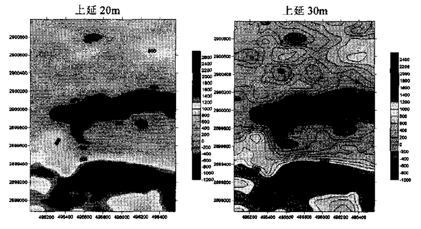
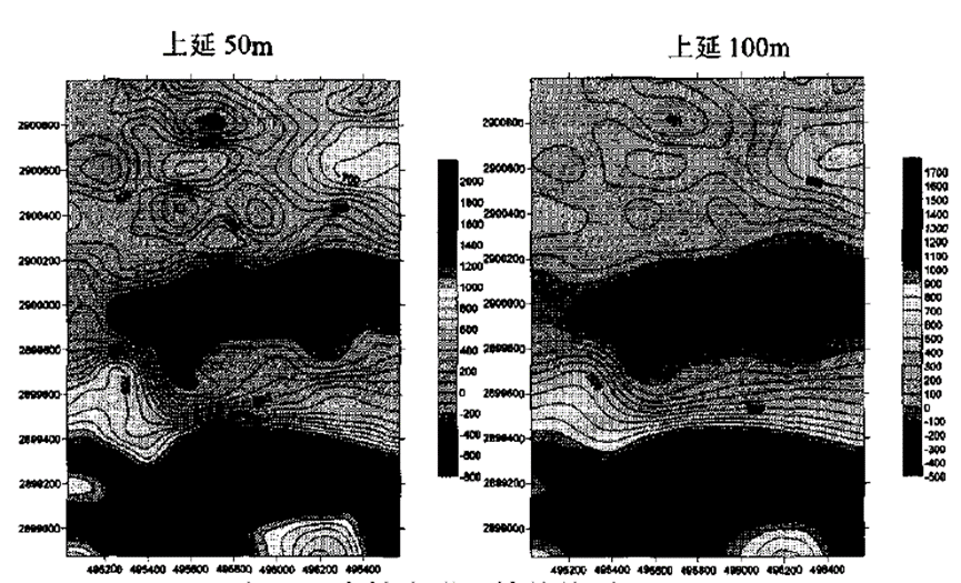

The analysis of the extension processing of the pole and different depths shows that: when the upper extension is extended from 20 to 500m, M5 disappears, and M6 almost disappears, which is caused by shallow materials: M1, M2, M3, and M4 anomalies still exist, and there is a trend of expanding into pieces, indicating that this anomaly is caused by deep high-magnetic materials.
In summary, the anomalies of M1, M2, M3, and M4 are large in scale and intensity, and are all located in favorable locations for mineralization. In particular, M1 is the best location for mineralization, and M1 is very likely to be related to magnetite. M2, M3, and M4 are affected by the surface interference, and the comprehensive method needs to be improved, so they need to be further verified. M5 and M6 are related to the rock mass and are not the focus of this work.
5 Conclusions
(1) Ground high-precision continuous magnetic survey is a small-point-distance ground magnetic field measurement technology. When the point distance is very small, the magnetic field curve is approximately continuously changing. Its advantage is that it can obtain more magnetic anomaly information and improve the exploration capability and interpretation accuracy of ground magnetic method.
(2) In actual work, ground high-precision magnetic survey has light instruments and simple operation. It can improve work efficiency and reduce labor intensity without increasing any cost and work difficulty.
(3) Ground high-precision magnetic survey has a high resolution in the interpretation of anomalies. It can not only distinguish geological structures, but also distinguish true and false anomalies through extension. It has high practicality in geological exploration.
Further reading | Technical solutions related to this article
In the field of resource exploration and engineering testing, accurate data is the key to success. As an innovator of resource and environmental instruments, Geotech has always taken high-precision electrical exploration technology as its core to provide reliable solutions for global users.
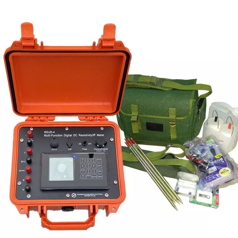
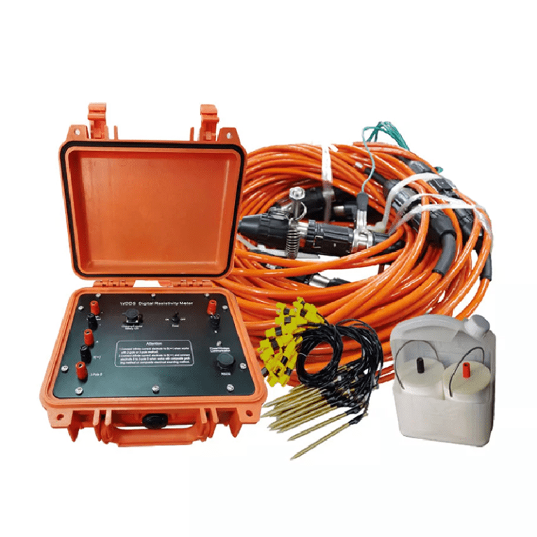
If you want to learn more about how the [Electrical Exploration System (ERT)] can help mineral exploration and geological research, please click on the electrical instrument product page to explore details, or visit Geotech’s official website to view the full range of exploration equipment (covering more than ten categories of products such as magnetometers, seismic nodes, and geological radars). Our technical team is on call at any time to customize scientific solutions for your project – making unknown strata a controllable data map.
FAQ
What is the main difference between a single tap and a double tap?
What is the principle of high-density electrical prospecting?
What are the advantages of high-density electrical method?
In what fields is the high-density electrical method generally used?
What are the application characteristics of high-density electrical method?