Welcome to Geotech!
Urban underground space detection solutions
Description
Seismic Solutions:Urban underground space detection solutions
Ⅰ. Overview
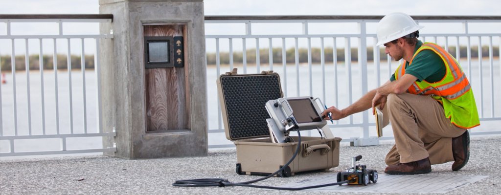
With the rapid development of cities, urban safety issues are becoming more and more prominent and the demand is becoming more and more urgent, including 0-100m high-precision detection of road collapse, pipeline safety, subway safety, etc., which is in a technical gap. At present, urban construction, emergency response, disaster prediction, and environmental protection urgently need high-precision underground detection.
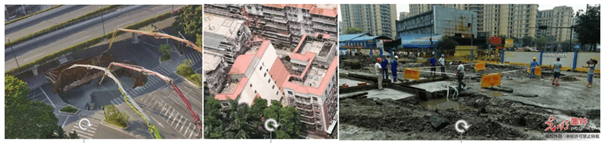

Problem 1: Road collapse

Problem 2: Leakage in pipelines and air-raid shelters
Problem 3: Subway safety collapse

II. Technical Status
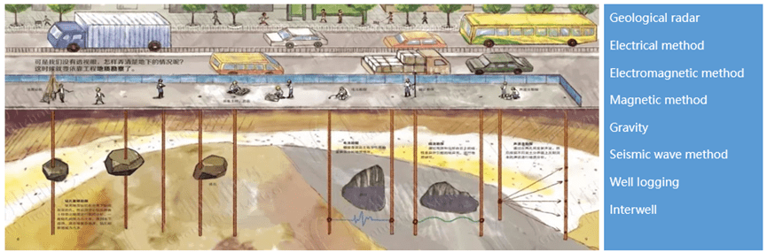
Urban underground space detection mainly includes the detection of underground stratum structure, bedrock surface depth and ups and downs, active faults, ground fissures, boulders, cavities, water-richness, bearing capacity, rock and soil quality and other geological information. It is the information basis for conducting geological surveys of multiple elements (space, resources, environment, disasters) of urban underground space and promoting transparent urban construction.
Difficulties:
- There are many interference factors, such as noise interference, human flow interference, industrial interference, electromagnetic interference, current interference, traffic track interference, building interference, etc.;
- Urban geophysical exploration requires high accuracy, and the accuracy generally needs to reach the meter level, even the centimeter level and millimeter level;
- Sometimes it is limited by the site, construction time, etc.
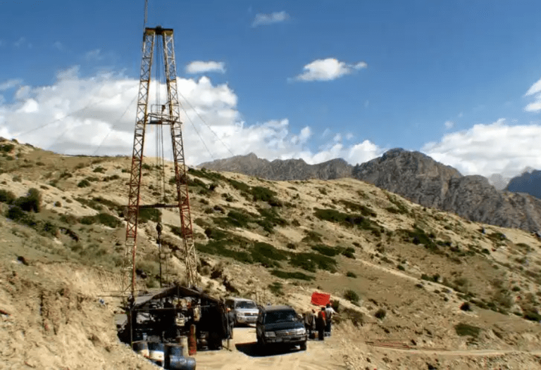
- Currently, shallow layer detection is mainly based on drilling – destructive, time-effective, costly, difficult to construct, and poor spatial control ability.
Application requirements:
- Urban geophysical exploration methods must be practical, flexible, fast, targeted, and have strong anti-interference capabilities.
- The industry urgently needs “two highs and one low” (high efficiency, high precision, and low cost) technical methods to improve service capabilities.
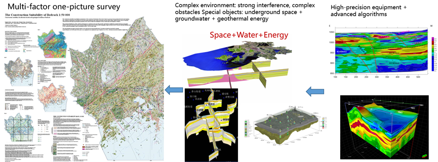
III. Integrated solution
Scale-optimized deployment of vibration sensors and other sensing devices, construction of data transmission networks and data centers, and use of big data and artificial intelligence algorithms to obtain a variety of application results.

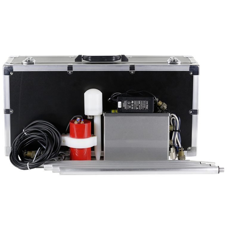
- Sensing: High-precision, wide-band sensors, low-noise digital node instruments are the main ones, supplemented by more than 20 high-precision sensors developed including fiber optic sensors, inclinometers, gyroscopes, etc., which are suitable for land, water, and underground scenes, effectively replacing imports, greatly reducing costs, and laying the foundation for large-scale deployment.
- Transmission: Low-power 4G/5G transmission technology, self-organizing network transmission technology, drone data recovery technology, compressed sensing data compression technology, etc. to achieve large-scale sensor access and high-speed transmission of massive data.
- Knowledge: Spatiotemporal big data promotes the development of cloud computing with technological innovation and model innovation.
IV. Technical Principles
IV. Application scenarios
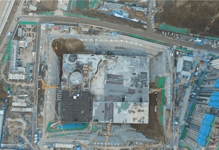
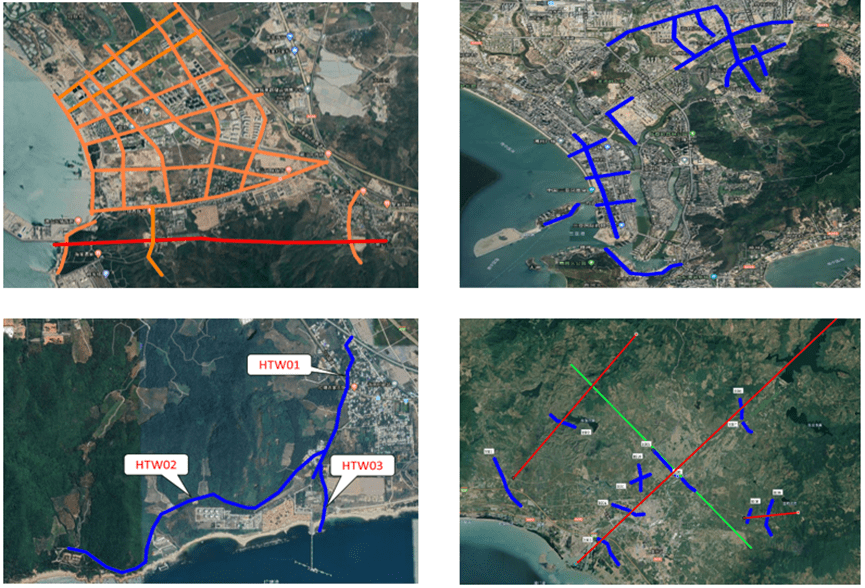
1. Application scenarios for underground space resource planning and design
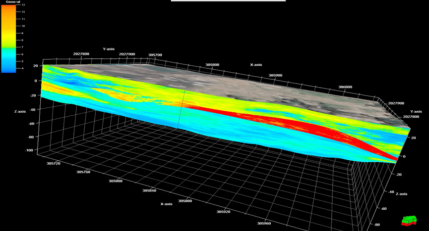
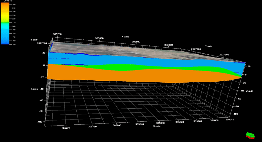
Using technologies such as three-component frequency imaging (internationally leading) to obtain a three-dimensional urban underground model with multiple elements (stratum structure, bedrock surface, caves, faults, weak interlayers, geotechnical indicators), it provides a data basis for urban underground resource assessment, planning, utilization and development.

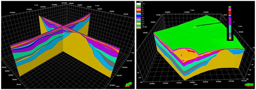
The physical parameter data of 105 boreholes in the preliminary and detailed survey stages of this area (including: water content, mass density, gravity density, porosity, saturation, plasticity index, liquid limit index, compression modulus, permeability coefficient, bearing capacity) were collected, and the data were sorted and loaded.
2. Application scenarios of geological disaster detection
Combined with satellite remote sensing, ground equipment uses resonance frequency, amplitude attenuation, dispersion, settlement, displacement, deformation and other characteristic calculations to achieve landslide and other geological disaster monitoring.
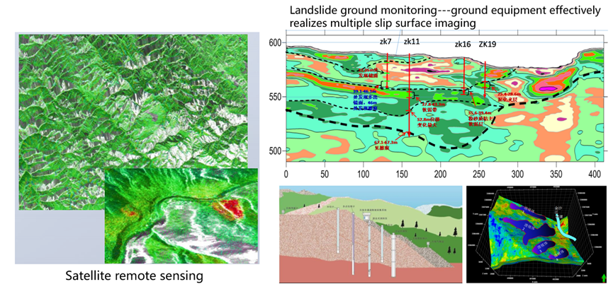
Landslide detection application in a certain area: a total of 13 two-dimensional survey lines were collected, processed, interpreted as layers and sliding surfaces.
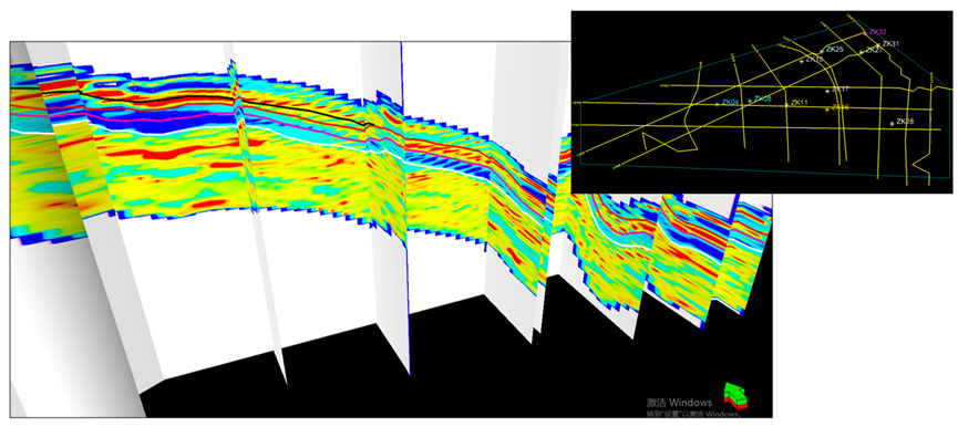
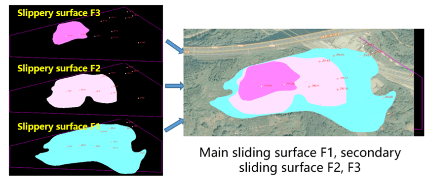
The landslide has the characteristics of multi-stage sliding. This study believes that there are mainly three sliding surfaces. Among them, the sliding surface F1 developed in the weak layer near the top of the bedrock is the main sliding surface. The sliding surfaces F2 and F3 are located in the weak layer above F1, with a gradually decreasing range, and are secondary sliding surfaces.

3. Application scenarios of road collapse detection
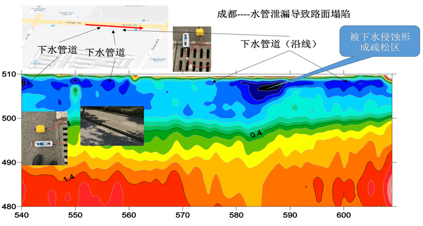
The time-varying characteristics of underground imaging amplitude, attenuation and dispersion characteristics are used to realize road collapse detection and monitoring.
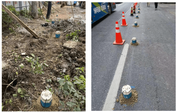
3.1 Application of road collapse caused by water pipe leakage
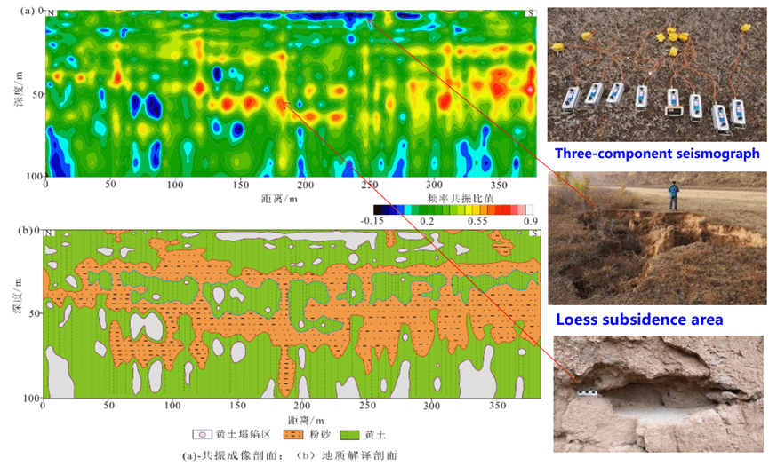
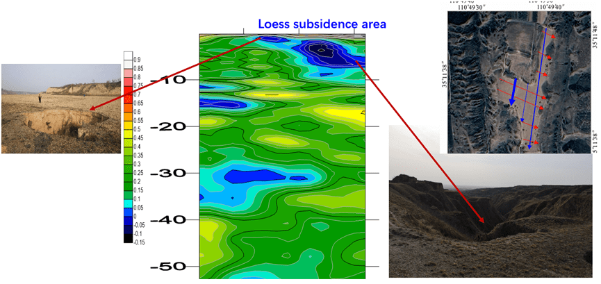
3.2 Application of loess subsidence survey
Loess is eroded by rainwater, forming multiple underground cavities, and the surface of the larger cavity area collapses.

4.Road Damage Subgrade Detection


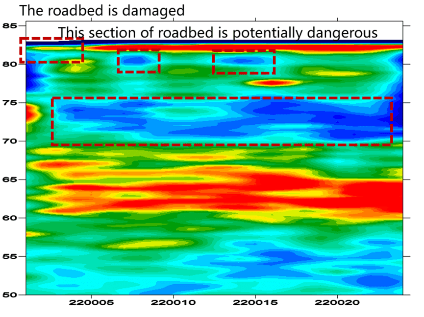
This loose layer is about 8 meters deep and may not have much impact in the short term, but may be potentially dangerous in the long term.
5. Subway application scenarios
Subway survey, construction safety, and monitoring. Taking a certain city subway as an example, a collapse occurred in front of a certain line shield.
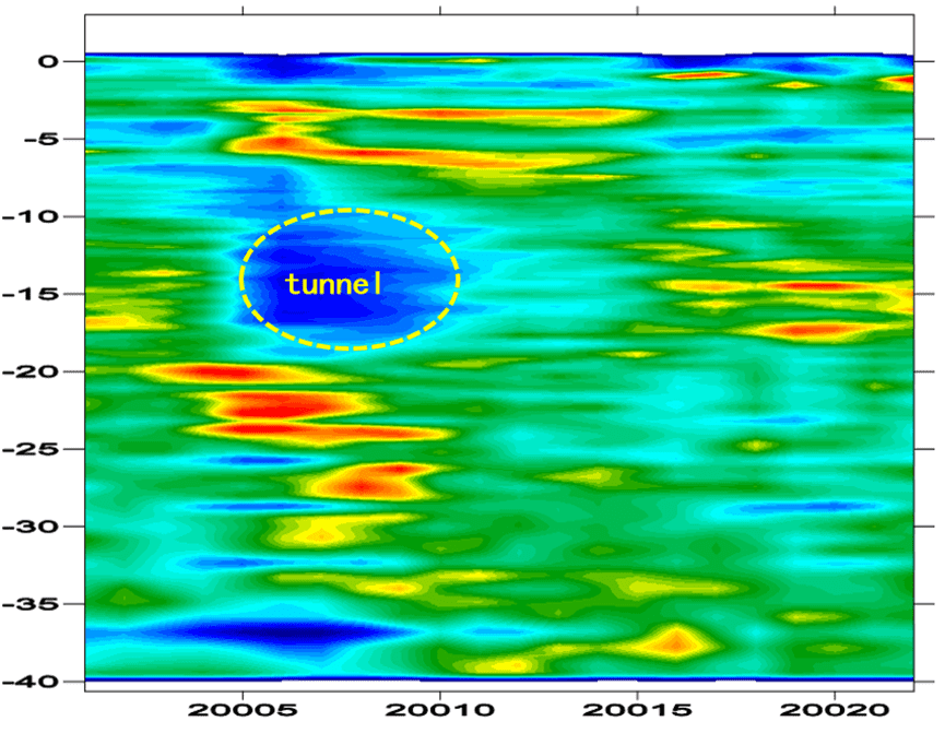
(1) Key engineering geological issues: During the shield tunneling process of the subway tunnel, an underground cavity was encountered and a collapse occurred at the face. Due to the existence of important buildings on the surface, it is urgent to detect the scope of the underground cavity encountered by the subway tunnel, and then evaluate its impact on the surface buildings.
(2) Survey line deployment: One two-dimensional survey line is deployed in the direction parallel to and perpendicular to the subway tunnel. Each survey line has 24 points and the point spacing is 1m.

In the frequency imaging section parallel to the tunnel direction, the tunnel and the shield machine are clearly imaged. It is inferred that the blue area in front of the shield machine is the underground cavity development area.
On the frequency imaging section perpendicular to the tunnel direction, the tunnel cross section is clearly imaged and is consistent with the tunnel burial depth on the section parallel to the tunnel direction.
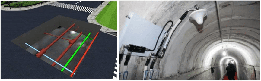
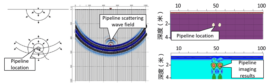
6. Underground pipeline application scenario
Sewer pipeline detection in a park
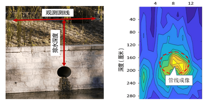
The left picture shows the on-site photos of underground pipeline detection and the photos of the exposed cement pipeline (pipeline buried 1.6 meters deep, pipe diameter 50 centimeters).
The right picture shows the geological radar imaging of the cement pipeline. The red dotted circle is the image of the underground pipeline. The buried depth of the pipeline can be accurately read in the red frame, which is consistent with the exposed measurement depth value.
FAQ
What is the main difference between a single tap and a double tap?
The double tap has a large current and can be used for IP testing to get more accurate data.
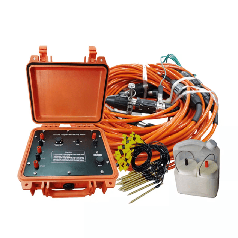
What is the principle of high-density electrical prospecting?
High-density apparent resistivity method is an array prospecting method, also known as automatic apparent resistivity system, which is developed from direct current method. Its function is equivalent to the combination of quadrupole sounding and electrical profiling method. The artificial electric field is formed by supplying electricity to the underground through electrodes. The distribution of the electric field is closely related to the distribution of the resistivity of the underground rock and soil medium. By measuring the artificial electric field at different parts of the surface, the distribution of the apparent resistivity of the underground medium is understood, and the underground geological structure is inferred and interpreted based on the distribution of the apparent resistivity of the rock and soil medium.
What are the advantages of high-density electrical method?
The principle of high-density electrical method is the same as that of traditional resistivity method. It is a combination method of multiple devices and multiple pole distances that integrates electrical depth sounding and electrical profiling method, which can obtain the conductivity characteristics of two-dimensional underground media. It has the characteristics of multi-device data acquisition in one pole arrangement, and highlighting abnormal information by obtaining ratio parameters, which greatly increases the amount of collected data, improves work efficiency, and ensures the accuracy and reliability of the pole running process.
This method is particularly sensitive to the water content of the surrounding rock. If the surrounding rock is broken and contains water, its apparent resistivity is significantly reduced. The apparent resistivity of intact and hard rock and soil is significantly higher than that of the surrounding rock in the fault zone or broken zone and water-rich zone. This method has a clear principle and intuitive images. It is a geophysical method with high resolution. In recent years, with the improvement of computer data acquisition technology, the exploration efficiency has been greatly improved, the coverage area and detection depth of the profile have been increased, reliable data can be obtained in a strong interference environment, the signal-to-noise ratio has been greatly improved, and the geological body can be accurately detected. This method has been widely and successfully applied in engineering and hydrogeological exploration and exploration of mineral and water resources.
In what fields is the high-density electrical method generally used?
(1) Application in coalfield and mine goaf detection
(2) Non-destructive detection of termite nests in dam foundations
(3) Karst and foundation surveys of railways, roads and tunnels
(4) Delineation of stratum lithology boundaries
(5) Survey of the leakage range of landfills
(6) Ancient tomb surveys
(7) Detection of sewage pipes
(8) Non-destructive testing of leakage in reservoirs and river dams
(9) Detection of bedrock fracture zones
(10) Soil salinity and water quality surveys
(11) Detection of ancient tunnels, air-raid shelters, metal burial sites, etc.
What are the application characteristics of high-density electrical method?
(1)The high-density resistivity method is based on the resistivity method, so it is suitable for all underground explorations with obvious conductivity differences;
(2)Any medium underground will have a weak polarization potential at the moment of power on and off, which will affect our measurement of the true potential difference. When the electrode distance is small, the loop current is large, which has little effect on the measurement results; when the electrode distance is too large, the interference potential is close to the effective potential, which has a greater impact on the measurement results. Therefore, due to the influence of the power supply electrode distance, the exploration depth cannot be too large, generally within 100m. When the conductivity of the soil medium is good, it can be appropriately increased, and the exploration depth in the soil medium with poor conductivity is appropriately smaller;
(3)It is generally less used in cities, near large transmission lines, etc. due to site restrictions and industrial stray current interference; 4. In areas such as concrete pavements and exposed bedrock surfaces, it is also less used due to the difficulty of electrode layout.