Welcome to Geotech!
-1.png)


Portable D+EM Electromagnetic System | Dual TEM+FEM | 5-10m Depth
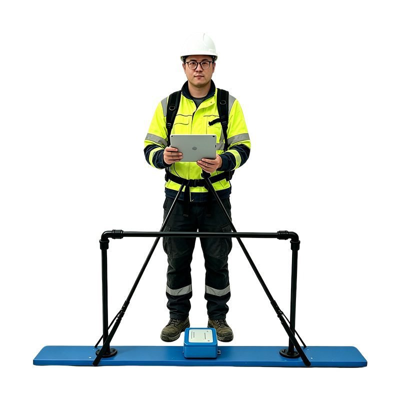
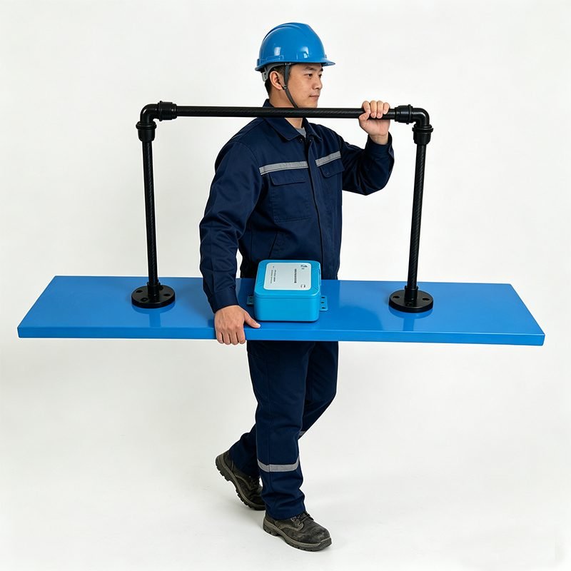



PRODUCT PARAMETERS
Description
 Overview
 Overview
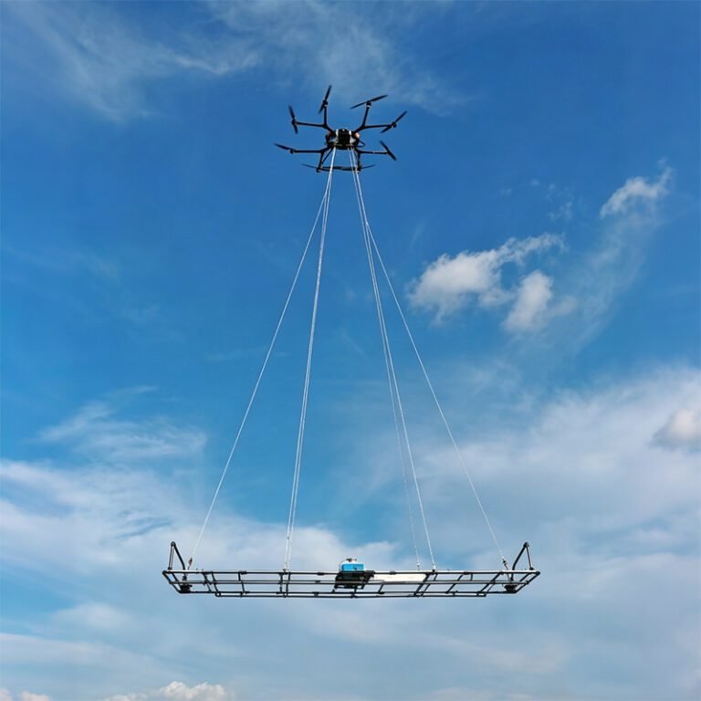
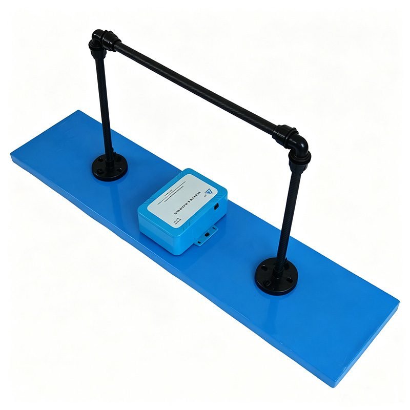
The D+EM portable electromagnetic system integrates dual-mode time-domain (D+TEM) and frequency-domain (D+FEM) electromagnetic detection technologies. It induces eddy currents in shallow subsurface geological units, enabling target identification and apparent resistivity estimation. Engineered for portability and field mobility, the system achieves an effective investigation depth of 5–10 m and is optimized for rapid near-surface geophysical surveys.
Features
1. Dual-Mode Electromagnetic Detection
The system integrates time-domain (D+TEM) and frequency-domain (D+FEM) electromagnetic detection technologies. Frequency-domain mode uses seven-frequency pseudo-random excitation from 128Hz to 8192Hz. Time-domain mode uses 12.5Hz bipolar square wave. This dual-mode approach provides complementary information. Frequency-domain data excels at resistivity mapping and layer discrimination. Time-domain data enhances conductive target detection and decay analysis.
2. Non-Contact Operation on Hardened Surfaces
The system operates in non-contact mode. No ground coupling or electrode contact is required. Measurements can be conducted directly on asphalt, concrete, and compacted surfaces. This eliminates the preparation time and surface damage associated with traditional galvanic methods. Urban utility surveys and road inspections are significantly accelerated.
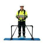
3. Single-Person Portable Design
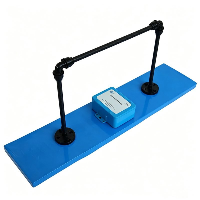
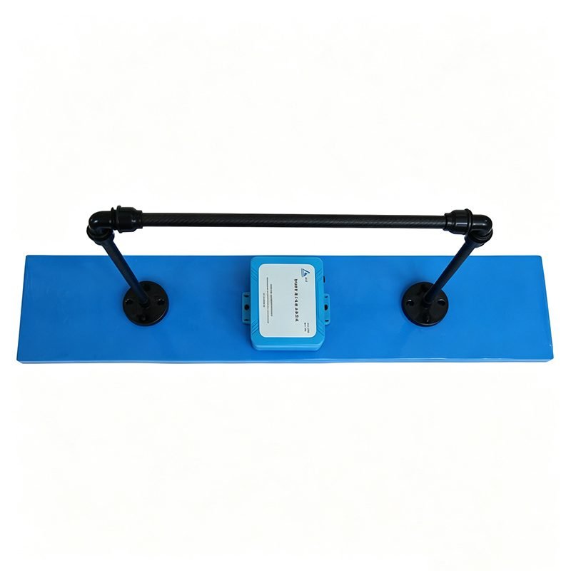
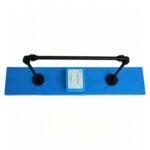
The system is engineered for single-person operation. The 1.2m coil version weighs 4kg with dimensions 120×25×3cm. The 2m coil version weighs 4.5kg with dimensions 200×25×3cm. Both configurations are carried and operated by one person. Rapid deployment and relocation between survey points minimize field time. No crew or vehicle support is needed.
4. Separated Coplanar Coil Configuration
The system uses separated coplanar coil geometry. Transmitter and receiver coils are arranged in a coplanar configuration with controlled separation. This design optimizes the primary field distribution and secondary field coupling. Signal quality is improved compared to coincident loop systems. Depth penetration and lateral resolution are balanced for near-surface applications.
5. WiFi Wireless Connection to Mobile Devices
The system connects via WiFi to a mobile phone or tablet. No cables between instrument and controller. Real-time data display and parameter adjustment are available on the operator’s device. GPS tagging and digital mapping are supported. Survey data is stored and exported directly from the mobile device.
6. High-Speed 24-Bit Acquisition
Sampling rate is 102.4kHz at 24-bit resolution. Output rate is 1Hz. The high sampling rate captures rapid electromagnetic transients. The 24-bit dynamic range resolves weak secondary fields. Data quality supports quantitative resistivity inversion and anomaly characterization.
Technical Principles
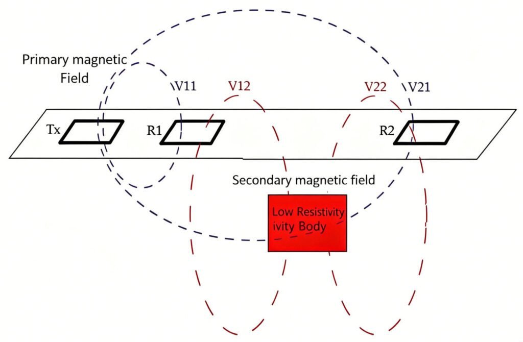
The Portable D+EM System operates on electromagnetic induction. The transmitter coil generates a time-varying magnetic field. This primary field induces eddy currents in conductive subsurface targets. The eddy currents generate a secondary magnetic field. The receiver coil measures this secondary field.
In frequency-domain (D+FEM) mode, seven discrete frequencies are transmitted simultaneously using pseudo-random coding. Each frequency penetrates to a different depth based on skin effect. Multi-frequency data enables layered resistivity modeling.
In time-domain (D+TEM) mode, a bipolar square wave is transmitted. After current shut-off, the secondary field decay is measured. Early-time data reflects shallow conductors. Late-time data reflects deeper structures. The decay curve shape indicates target conductivity and geometry.
| Mode | Excitation | Frequency | Best Application | Depth Sensitivity |
|---|---|---|---|---|
| D+FEM | Seven-frequency pseudo-random | 128-8192Hz | Resistivity layering, pipeline detection | 0-5m |
| D+TEM | 12.5Hz bipolar square wave | 12.5Hz base | Conductive targets, cavity mapping | 3-10m |
The combination of both modes provides comprehensive shallow subsurface characterization in a single survey.
Specifications
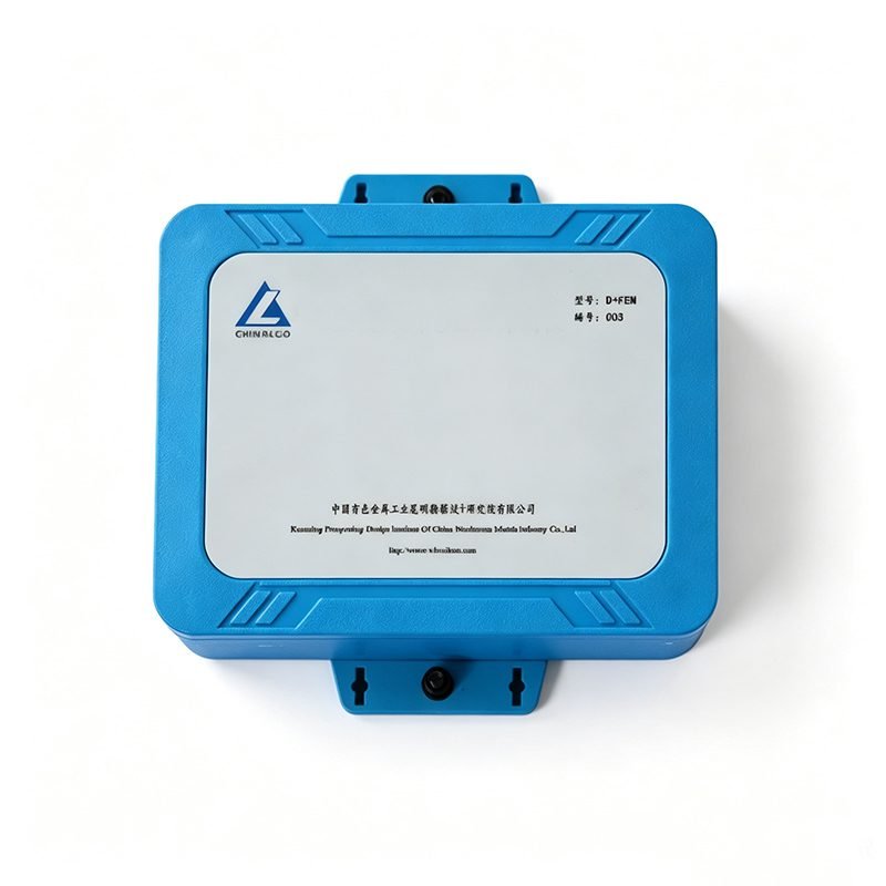
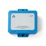
The Portable D+EM System comprises three core components. Transmitter Coil Assembly. Receiver and Acquisition Unit. Mobile Control Device.
1. Transmitter Coil Assembly
| Parameter | 1.2m Coil | 2m Coil |
|---|---|---|
| TX magnetic moment | 8A·m² | 571A·m² |
| Dimensions | 120×25×3cm | 200×25×3cm |
| Weight | 4kg | 4.5kg |
| Coil type | Separated coplanar |
2. Receiver and Acquisition Unit
| Parameter | Specification |
|---|---|
| Sampling rate | 102.4kHz |
| Sampling bit depth | 24 bits |
| Output rate | 1Hz |
| Power supply | 12V |
| Connection method | WiFi to mobile phone or tablet |
3. Mobile Control Device
Any WiFi-enabled smartphone or tablet serves as the control and display unit. The dedicated app provides real-time waveform display, parameter configuration, GPS positioning, and data storage. Survey lines and grids are planned and visualized on the device. Data export formats include CSV and proprietary format for third-party inversion software.
Applications
1. Utility Pipeline Localization
Locate municipal public utilities and underground assets. Metallic pipes, cables, and conduits are detected through their conductive contrast with surrounding soil. Non-contact operation enables surveys on paved roads and sidewalks without surface damage. Pipeline depth and orientation are estimated from multi-frequency data.
2. Karst Cavity Mapping
Detect underground cavities, sinkholes, and voids in karst terrain. Air-filled cavities present high-resistivity anomalies. Water-filled cavities show low-resistivity responses. The dual-mode system discriminates between cavity types. Hazard assessment and engineering planning are supported.
3. Overburden Thickness Assessment
Measure the thickness of unconsolidated surficial deposits over bedrock. The resistivity contrast between soil/weathered layer and competent bedrock is resolved. Frequency-domain data maps layer boundaries. Time-domain data confirms bedrock depth. Foundation design and quarry planning benefit.
4. Shallow Geological Structural Interpretation
Map faults, fractures, and lithological contacts in the upper 10 meters. Conductive fracture zones and resistive dykes are identified. Structural orientation and continuity are traced along survey lines. Geological mapping and hazard zonation are enhanced.
5. Archaeological Survey
Detect buried walls, foundations, hearths, and ditches. Archaeological features often present resistivity contrasts with natural soils. Non-invasive survey preserves site integrity. Rapid coverage of large areas prioritizes excavation targets.
6. Unconsolidated Layer–Bedrock Interface Detection
Delineate the transition from loose sediments to competent bedrock. The interface is a critical parameter for construction, mining, and groundwater studies. Dual-mode data constrains the depth and geometry of the boundary. Drill planning and resource estimation are optimized.
Cases
Case 1: Urban Pipeline Detection
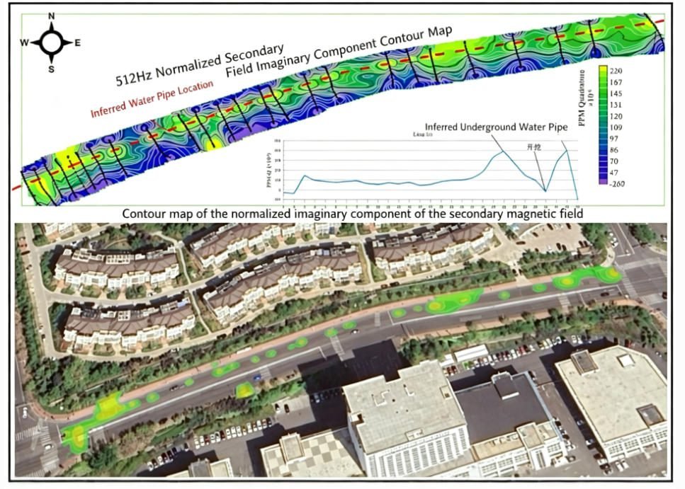
A municipal utility mapping project required locating buried water mains, gas pipes, and electrical cables in a downtown area. Traditional methods required road excavation for electrode placement. The Portable D+EM System was deployed in non-contact mode directly on asphalt surfaces. The seven-frequency pseudo-random mode identified multiple conductive utilities. Depth estimates correlated with utility records. The survey was completed by one operator in a single day. No road closures or surface damage occurred.
FAQ
In gravity exploration (SI), what is the unit of gravity? How to convert gravity units between SI and CGS?
① In SI, it is m·s-2, and one percent of it is the international unit abbreviation g.u.;
② Conversion between SI and CGS: 1g.u.=10-1 mGal
What are gravitational field and gravitational potential?
Gravitational field: The space around the earth with gravity is called the gravitational field.
Gravitational potential: The gravitational potential W in the gravitational field is equal to the work done by a particle of unit mass moving from infinity to that point.
What is the normal gravity field of the earth? What are the rules for the change of the normal gravity field with latitude and altitude?
① The normal gravity field of the earth: Assuming that the earth is a rotating ellipsoid (reference plane), the surface is glossy, the internal density is uniform, or it is distributed in concentric layers, the density of each layer is uniform, and the deviation of the shape of the ellipsoid from the geoid is very small, then the gravity field generated by the earth is the normal gravity field.
② The normal gravity value is only related to the latitude, the smallest at the equator and the largest at the poles, with a difference of about 50,000 g.u.; the rate of change of the normal gravity value with latitude is the largest at 45° latitude, and zero at the equator and the poles; the normal gravity value decreases with increasing altitude, and its rate of change is -3.086 g.u.. The main feature of the long-term change is the "westward drift" of the geomagnetic elements, both the dipole field and the non-dipole field drift westward, and have a global nature.
What is the relationship between gravitational field strength and gravitational acceleration?
The gravitational field strength is equal to the gravitational acceleration in both numerical and dimensional terms, and the two are in the same direction. In gravity exploration, all references to gravity refer to gravitational acceleration. The gravitational field strength at a point in space is equal to the gravitational acceleration at that point.
What is gravity exploration?
Gravity exploration is an exploration method that is based on the density difference of rocks and ores. Since density difference will cause local changes in the normal gravity field of the earth (i.e. gravity anomaly), it is used to solve geological problems by observing and studying gravity anomalies.