Welcome to Geotech!
-1.png)

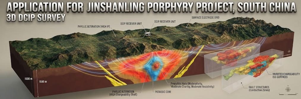
Application for Jinshanling Porphyry Project, South China丨3D DCIP survey
Description
Overview:3D DCIP survey technology enables volumetric subsurface characterization for deep mineral exploration. This guide explains how 3D DCIP survey methods advance deep target detection, and evaluates induced polarization mineral exploration outcomes across induced polarization mineral exploration projects in Chinese porphyry mining districts.
Ⅰ. Overview of 3D DCIP Geophysical Technology
1. Core Definition
3D DCIP (Direct Current Induced Polarization) survey is an advanced electrical geophysical technique that generates volumetric models of both subsurface electrical resistivity and chargeability. It extends traditional 2D profiling to full three-dimensional imaging of subsurface electrical properties. The method is the state-of-the-art geophysical tool for deep metal exploration under cover.
DCIP surveys inject controlled direct current through ground electrode arrays. They measure both the steady-state voltage response and the transient voltage decay after current termination. This produces two independent datasets: bulk electrical conductivity and interfacial chargeability. Dual-parameter characterization significantly reduces interpretation ambiguity compared to single-property methods.
2. Technology Evolution
Induced polarization methods evolved from early 1D soundings through 2D cross-sectional profiling to modern 3D volumetric imaging. Early IP surveys used sparse 2D lines with limited lateral resolution. 3D array configurations deliver isotropic volumetric data with uniform resolution in all directions.
This evolution has dramatically improved targeting accuracy for deep mineral deposits. It has also enabled detection of smaller and lower-grade mineralized zones. 3D DCIP is now the standard pre-drilling geophysical tool for porphyry and other disseminated mineral systems.
Ⅱ. Physical Principles and Technical Advantages
1. Measurement Principles
DCIP operates on two complementary physical phenomena measured in sequence. First, injected DC current produces a steady-state potential field in the subsurface. This primary measurement determines apparent electrical resistivity of the bulk rock-fluid system.
After current termination, polarization effects at mineral-fluid interfaces produce a decaying secondary voltage. This induced polarization response reflects the electrochemical properties of sulfide minerals and clay materials. Chargeability is quantified from the amplitude and decay characteristics of this secondary signal.
The two parameters respond to different geological features. Resistivity maps porosity, saturation and bulk mineral content. Chargeability specifically identifies electronic conductors including sulfide minerals and graphite. Together they provide much stronger geological constraints than either parameter alone.
2. 3D Array Configuration
3D DCIP surveys deploy electrode grids across the survey area rather than single lines. Both current and potential electrodes are distributed in a regular grid pattern. Dense station spacing enables true 3D inversion of the subsurface response.
Modern 3D surveys use hundreds to thousands of electrode stations. Intelligent switching systems cycle through electrode combinations efficiently. This produces a volumetric dataset with consistent spatial sampling in all directions.
3. Comparative Method Performance
The following table compares 3D DCIP with conventional geophysical methods for mineral exploration. It highlights the relative advantages of each technique for different exploration objectives.
| Method | Dimensionality | Output Parameters | Typical Depth Range | Target Discrimination | Lateral Resolution |
|---|---|---|---|---|---|
| 2D Resistivity | 2D profile | Resistivity only | 5 – 300 m | Low | 0.5 – 3 m along line |
| 2D IP | 2D profile | Resistivity + chargeability | 5 – 300 m | Moderate | 0.5 – 3 m along line |
| 3D DCIP | 3D volume | Resistivity + chargeability | 10 – 500 m | High | 5 – 20 m isotropic |
| TEM | 3D volume | Conductivity only | 20 – 800+ m | Low | 10 – 30 m |
| Magnetic | 2D/3D map | Susceptibility only | Surface to 100m | Low | 10 – 50 m |
4. Key Technical Advantages
3D DCIP provides several critical advantages for mineral exploration:
- Dual-parameter discrimination: Distinguishes sulfide mineralization from other conductive features like brine or graphite
- Volumetric imaging: True 3D definition of ore body geometry and structural controls
- Deep penetration: Effective under hundreds of meters of barren overburden
- Target ranking: Quantifies chargeability contrast for objective prospect ranking
- Reduced drilling risk: Improves first-pass success rate for exploration drill holes
Ⅲ. Application to Porphyry Polymetallic Systems
1. Porphyry Deposit Geophysical Response
Porphyry mineral systems present characteristic geophysical signatures. Disseminated sulfide mineralization produces measurable chargeability anomalies. Stockwork and sheeted vein zones create distinct conductivity and chargeability patterns.
Porphyry intrusions themselves often produce resistivity contrasts with host rock. Alteration halos produce broader, lower-amplitude geophysical signatures. Skarn zones at intrusive contacts can produce very high-grade chargeability anomalies.
The geometry of porphyry systems makes them ideal targets for 3D survey methods. Their large vertical extent and irregular shape are poorly resolved by 2D profiling. Volumetric imaging captures the full three-dimensional form of the mineral system.
2. Hidden Intrusion Detection
A major strength of 3D DCIP is detection of blind porphyry intrusions under cover. Many porphyry systems have no surface expression of mineralization. Conventional exploration methods may miss these hidden systems entirely.
Chargeability anomalies from disseminated sulfides can be detected through significant overburden thickness. 3D inversion defines the geometry of the mineralized zone at depth. This enables targeting of intrusive centers that would otherwise remain undiscovered.
3. Vertical Extent Evaluation
Porphyry systems often extend vertically for hundreds to thousands of meters. Defining the full vertical extent of mineralization is critical for resource estimation. 2D profiling commonly underestimates vertical continuity and depth extension.
3D DCIP surveys map the full vertical profile of mineral systems. They identify depth of mineralization, ore body plunge and vertical grade distribution. This information is essential for resource calculation and mine planning.
Ⅳ. Field Validation Case Study: Jinshanling Porphyry Project, South China
1. Project Background
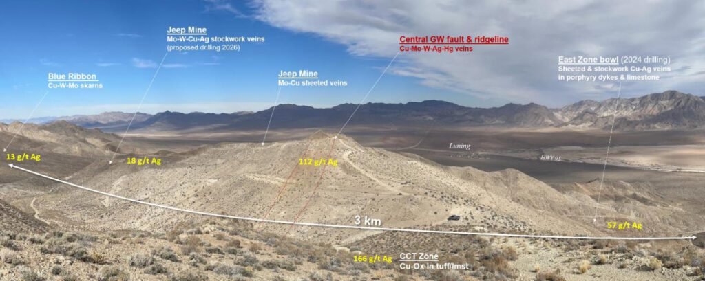
The Jinshanling polymetallic porphyry-skarn system in northeastern Jiangxi, South China was the subject of a 3D DCIP technology deployment by Geotech. The district had 60+ years of sporadic historical exploration by provincial geological teams with widely spaced drilling. Historical work established general mineral system character but failed to define deep extensions and blind intrusive bodies.
Geotech was commissioned to design and execute a full-coverage 3D array DCIP survey over the central Lingtou ore block of the system. The project objective was to characterize the subsurface conductivity and chargeability distribution and rank targets for drill testing. Geotech deployed a dense grid electrode layout and applied proprietary 3D inversion algorithms to process the dual-parameter dataset.
2. Survey Design and Targeting
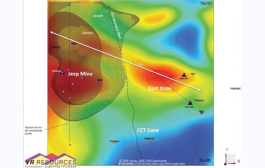
The DCIP survey used a dense 3D electrode array across the 1,000-meter-wide target anomaly. Both conductivity and chargeability data were collected and inverted into volumetric models. The survey identified a strong, vertically extensive chargeability anomaly coincident with a broad conductivity low.
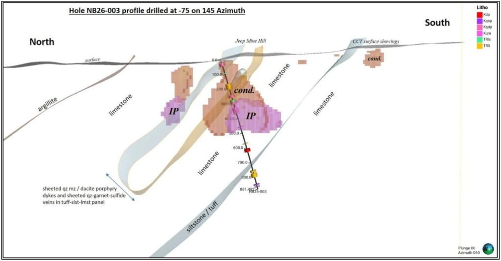
Geotech’s interpretation indicated a deep-reaching mineralized system centered on a porphyry intrusion. The anomaly extended from surface to depths beyond 800 meters. Higher chargeability values at depth suggested increasing mineral grade at the intrusive contact zone. The central anomaly was selected as the drill target for hole ZK26-003.
3. Drill Validation Results
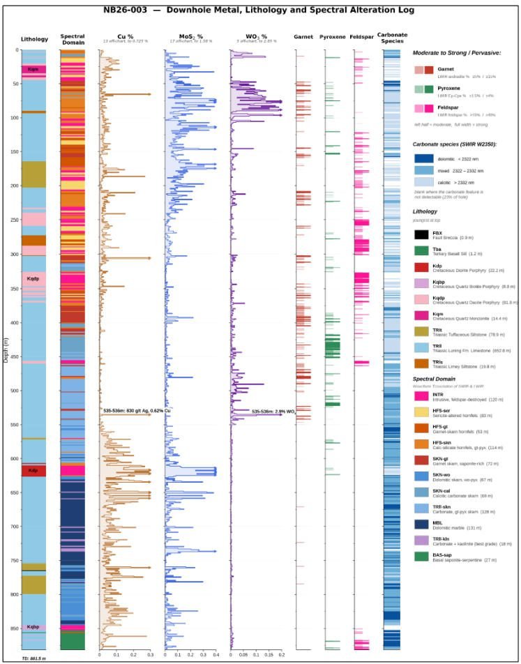
Drilling confirmed the geophysical interpretation with a high degree of accuracy. Two broad mineralized intervals were intersected, matching the geophysical zonation predicted by Geotech’s model.
| Mineral Interval | Depth Range | Thickness | Average CuEq | Predicted vs Actual |
|---|---|---|---|---|
| Upper Moly-Tungsten Zone | 0 – 317 m | 317 m | 0.77% CuEq | Matches upper anomaly |
| Lower Copper-Moly Zone | 460 – 879 m | 419 m | 0.48% CuEq | Matches deep anomaly |
A hidden diorite porphyry intrusion was intersected at 604 meters depth, exactly as predicted by the chargeability model. This intrusive body had no surface expression and was not identified in 60 years of historical work. It produced a strong chargeability anomaly of 0.98% CuEq over 31 meters thickness. High-grade skarn mineralization at the contact returned peak values up to 33.43% CuEq.
The drill hole demonstrated continuous mineralization across 2,892 feet of core. Mineralization remained open at the bottom of the hole. This confirmed deep vertical extension of the system far beyond historical concepts.
4. Lateral Extension Potential
The chargeability anomaly was approximately 1,000 meters across at the target horizon. The single drill hole tested only the central portion of the geophysical feature. Significant strike extension potential was indicated along the mineralized trend.
Surface mineralization extended for 2.1 km along strike to the east. Historical drill holes 2,100 meters east confirmed mineralization but at lower grades. This demonstrated the district-scale potential of the geophysical anomaly defined by Geotech’s survey.
Ⅴ. Exploration Value and Technical Economics
1. Exploration Efficiency Impact
3D DCIP technology dramatically improves exploration efficiency in covered porphyry terrains. It identifies priority targets for drilling with much higher success rates than random or geology-only programs.
In the Jinshanling case study, a single deep drill hole validated a billion-dollar-scale mineral system. The geophysical survey cost was a small fraction of the value of the resource identified. This represents extremely high exploration leverage for the method.
2. Resource Definition Benefits
Volumetric imaging enables much more accurate resource estimation earlier in the exploration cycle. 3D models of chargeability distribution support better geological modeling of the mineral system. This reduces uncertainty in grade and tonnage calculations.
Better early-stage resource definition improves decision quality. It enables better go/no-go decisions at each stage of exploration. Companies can advance better targets and drop weaker ones earlier.
3. Cost Effectiveness
Compared to systematic drilling programs, 3D DCIP surveys are very cost-effective. They cover large areas rapidly and identify the best parts of systems for drill testing.
Capital efficiency improves by focusing drilling on highest-potential targets. Fewer dry holes and better discovery rates reduce overall finding costs. This makes 3D DCIP standard practice for porphyry exploration in covered terranes.
Ⅵ. Method Selection and Implementation Guidance
1. When to Select 3D DCIP
3D DCIP is the preferred method when:
- Exploring for disseminated sulfide mineral systems under cover
- Targeting porphyry, skarn and volcanogenic massive sulfide deposits
- Defining 3D geometry of known mineralized zones
- Ranking prospects for follow-up drilling
- Exploring covered districts with limited outcrop information
2. Survey Design Best Practices
Effective 3D DCIP surveys follow established design principles:
- Array size extends beyond target zone by at least one-third depth
- Station spacing matches expected target size and depth
- Current injection points distributed for uniform depth penetration
- Sufficient tie lines and repeat stations for quality control
3. Integration with Complementary Methods
3D DCIP works best as part of a multi-method exploration program. Magnetic and EM surveys provide efficient regional reconnaissance. Gravity and magnetic methods help identify structural controls at district scale.
Detailed follow-up uses geological mapping, geochemical sampling and trenching. Drilling provides final validation and resource definition. Integrated programs balance cost, resolution and risk across exploration stages.
Related Articles
| Anchor Text | Recommended Internal Page | Core Content |
|---|---|---|
| Induced Polarization Method | Induced Polarization (IP) Method: Comprehensive Technical Guide | Explains IP principles, chargeability, acquisition methods, interpretation, and mineral exploration applications. |
| Electrical Resistivity Tomography | Electrical Resistivity Tomography: Technical Guide | Introduces resistivity imaging principles, 2D/3D inversion, and subsurface applications. |
| Resistivity Surveying Techniques | Resistivity Surveying Techniques | Compares resistivity survey configurations and their technical applications. |
| Geophysical Exploration Methods | Basic Principles of Geophysical Exploration | Provides broader context for geophysical methods and subsurface exploration. |
| Geophysical Equipment | ERT Instruments and Geophysical Equipment Guide | Introduces geophysical instrument categories and electrical exploration systems. |
Reference Sources
| Authority | Reference | Core Content |
|---|---|---|
| Geophysical Journal International | Inductive Source Induced Polarization | Technical research on IP responses, chargeability, and 3D inversion concepts. |
| Society of Exploration Geophysicists / Academic Literature | Induced Polarisation Methods in Mineral Exploration | Foundational discussion of IP principles, survey configurations, and mineral exploration applications. |
| CSEG Recorder | Applications of DC Resistivity and Magnetotelluric Methods in Exploration | Discusses 3D DCIP and MT applications in porphyry exploration and geological interpretation. |
| Geophysical Conference Paper | Application of DCIP Surveys for Porphyry Deposits | Case studies illustrating DCIP applications in porphyry-style mineral exploration. |
| Journal of Applied Geophysics | IP with TEM Soundings at the El Arco Porphyry Copper Deposit | Research on integrating induced polarization and transient electromagnetic sounding for mineral discrimination. |
FAQ
Q1. What is a 3D DCIP survey?
A 3D DCIP survey combines direct-current resistivity and induced polarization measurements to investigate underground electrical properties. The resulting data are inverted into three-dimensional resistivity and chargeability models. In mineral exploration, these models help characterize electrical anomalies that may be associated with sulfide mineralization, alteration, or geological structures.
Q2. Why is 3D DCIP used in porphyry exploration?
3D DCIP is used because resistivity and chargeability can provide complementary information about porphyry-related geological systems. Chargeability may help identify polarizable materials such as disseminated sulfides, while resistivity helps map electrical contrasts associated with lithology, alteration, and fluids. Drilling and geological evidence are required to validate targets.
Q3. Can 3D DCIP directly identify copper ore?
No. 3D DCIP measures electrical properties rather than copper grade or economic value. Elevated chargeability may be associated with sulfides, but not all sulfides contain economic copper. Resistivity and chargeability anomalies must be interpreted alongside geology, geochemistry, drilling, and other exploration data before a mineralization hypothesis can be confirmed.
Q4. What is the difference between resistivity and chargeability?
Resistivity describes how strongly a material opposes electrical current, whereas chargeability describes its polarization response to electrical stimulation. In a DCIP survey, resistivity helps characterize electrical contrasts, while chargeability can help identify polarizable materials. Their combined interpretation may provide more geological context than either parameter alone.
Q5. How does 3D DCIP support drill targeting?
3D DCIP supports drill targeting by mapping the geometry, depth, and continuity of resistivity and chargeability anomalies. Geophysicists compare these models with geological structures, alteration, geochemistry, and existing boreholes to prioritize targets. Drilling then tests whether the interpreted anomalies correspond to the expected geological features and mineralization.
FAQ
What is the main difference between a single tap and a double tap?
The double tap has a large current and can be used for IP testing to get more accurate data.
What is the principle of high-density electrical prospecting?
High-density apparent resistivity method is an array prospecting method, also known as automatic apparent resistivity system, which is developed from direct current method. Its function is equivalent to the combination of quadrupole sounding and electrical profiling method. The artificial electric field is formed by supplying electricity to the underground through electrodes. The distribution of the electric field is closely related to the distribution of the resistivity of the underground rock and soil medium. By measuring the artificial electric field at different parts of the surface, the distribution of the apparent resistivity of the underground medium is understood, and the underground geological structure is inferred and interpreted based on the distribution of the apparent resistivity of the rock and soil medium.
What are the advantages of high-density electrical method?
The principle of high-density electrical method is the same as that of traditional resistivity method. It is a combination method of multiple devices and multiple pole distances that integrates electrical depth sounding and electrical profiling method, which can obtain the conductivity characteristics of two-dimensional underground media. It has the characteristics of multi-device data acquisition in one pole arrangement, and highlighting abnormal information by obtaining ratio parameters, which greatly increases the amount of collected data, improves work efficiency, and ensures the accuracy and reliability of the pole running process.
This method is particularly sensitive to the water content of the surrounding rock. If the surrounding rock is broken and contains water, its apparent resistivity is significantly reduced. The apparent resistivity of intact and hard rock and soil is significantly higher than that of the surrounding rock in the fault zone or broken zone and water-rich zone. This method has a clear principle and intuitive images. It is a geophysical method with high resolution. In recent years, with the improvement of computer data acquisition technology, the exploration efficiency has been greatly improved, the coverage area and detection depth of the profile have been increased, reliable data can be obtained in a strong interference environment, the signal-to-noise ratio has been greatly improved, and the geological body can be accurately detected. This method has been widely and successfully applied in engineering and hydrogeological exploration and exploration of mineral and water resources.
In what fields is the high-density electrical method generally used?
(1) Application in coalfield and mine goaf detection
(2) Non-destructive detection of termite nests in dam foundations
(3) Karst and foundation surveys of railways, roads and tunnels
(4) Delineation of stratum lithology boundaries
(5) Survey of the leakage range of landfills
(6) Ancient tomb surveys
(7) Detection of sewage pipes
(8) Non-destructive testing of leakage in reservoirs and river dams
(9) Detection of bedrock fracture zones
(10) Soil salinity and water quality surveys
(11) Detection of ancient tunnels, air-raid shelters, metal burial sites, etc.
What are the application characteristics of high-density electrical method?
(1)The high-density resistivity method is based on the resistivity method, so it is suitable for all underground explorations with obvious conductivity differences;
(2)Any medium underground will have a weak polarization potential at the moment of power on and off, which will affect our measurement of the true potential difference. When the electrode distance is small, the loop current is large, which has little effect on the measurement results; when the electrode distance is too large, the interference potential is close to the effective potential, which has a greater impact on the measurement results. Therefore, due to the influence of the power supply electrode distance, the exploration depth cannot be too large, generally within 100m. When the conductivity of the soil medium is good, it can be appropriately increased, and the exploration depth in the soil medium with poor conductivity is appropriately smaller;
(3)It is generally less used in cities, near large transmission lines, etc. due to site restrictions and industrial stray current interference; 4. In areas such as concrete pavements and exposed bedrock surfaces, it is also less used due to the difficulty of electrode layout.