Welcome to Geotech!
-1.png)

Density Electrical System for Landfill Leachate Distribution and Liner Investigation
Description
Ⅰ. Project Background: Why Landfill Investigation Requires Geophysical Methods
Municipal solid waste landfills are essential facilities for modern waste management. However, long-term environmental protection depends on effective containment systems, including landfill liners, leachate collection systems, and continuous environmental monitoring.
Leachate generated from waste decomposition contains dissolved substances and conductive fluids that may migrate through surrounding geological formations if containment systems are compromised. Therefore, identifying possible leachate accumulation zones and evaluating subsurface conditions are important tasks for landfill operators, environmental consultants, and engineering organizations.
Traditional investigation methods, such as drilling and direct sampling, provide valuable information at specific locations. However, their spatial coverage is often limited. Geophysical methods, especially electrical resistivity techniques, provide a non-invasive approach for mapping subsurface electrical variations over larger areas.
In this landfill investigation case, Geotech applied the WGMD-4 High-Density Electrical Method System together with the WDZS-3 Multifunctional Electrical Water Detector to analyze possible leachate distribution and investigate resistivity characteristics related to the landfill liner interface.
The original project used:
- 2D electrical resistivity profiles for subsurface interpretation.
- 3D resistivity modeling for spatial visualization.
- A reported 4 Ω·m resistivity threshold to assist interpretation of possible leachate-rich zones.
It should be emphasized that the 4 Ω·m value represents a project-specific interpretation criterion based on available site information. It should not be considered a universal threshold for all landfill environments.
Ⅱ. Investigation Method and Equipment
1. Principle of High-Density Electrical Resistivity Investigation
High-density electrical surveys investigate underground structures by measuring how the subsurface responds to injected electrical current.
During the survey, current is introduced into the ground through current electrodes, while voltage differences are measured through potential electrodes. The system calculates apparent resistivity based on the relationship between current, voltage, and electrode geometry.
The basic equation is:\[ \rho_a = K \frac{\Delta V}{I} \]
Where:
- ρa = apparent resistivity (Ω·m)
- K = geometric factor determined by electrode arrangement
- ΔV = measured voltage difference
- I = injected current
Apparent resistivity represents the electrical response of a volume of subsurface material rather than a single underground layer.
The measured response depends on:
- Geological materials.
- Water content.
- Pore-fluid conductivity.
- Clay content.
- Mineral composition.
- Temperature conditions.
- Survey geometry.
Because leachate often contains dissolved ions, it may produce lower resistivity responses compared with surrounding dry or less conductive materials. However, low resistivity is not unique to leachate.
Depending on geological conditions, similar anomalies may also result from:
- Clay-rich layers.
- Saline groundwater.
- High moisture zones.
- Weathered materials.
- Naturally conductive formations.
Therefore, resistivity interpretation should always combine geophysical results with geological, hydrological, and engineering information.
2. Equipment Used in the Landfill Investigation
The original investigation used two main Geotech systems:
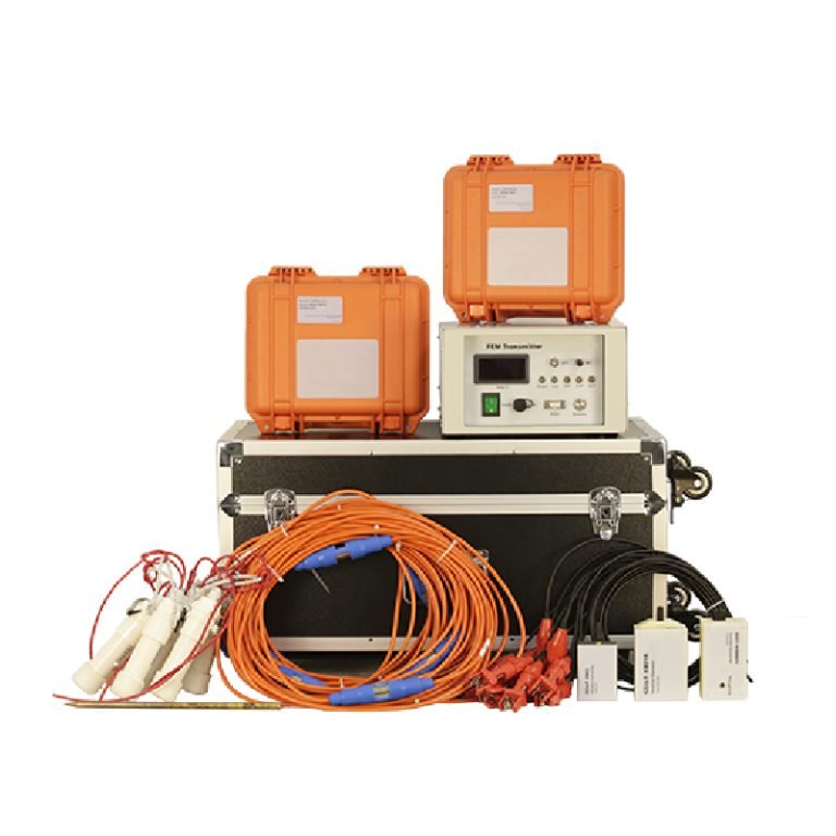
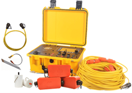
WGMD-4 High-Density Electrical Method System
The WGMD-4 system is designed for high-density electrical data acquisition. It integrates measurement control, electrode switching, and field data collection functions to support electrical resistivity investigations.
The system can be applied to:
- Environmental investigation.
- Groundwater exploration.
- Engineering geological surveys.
- Underground structure detection.
- Geological boundary mapping.
The specific configuration may vary depending on project requirements, electrode numbers, survey objectives, and field conditions.
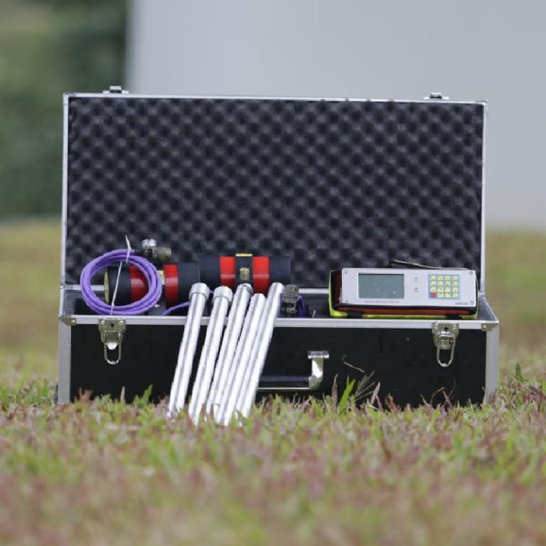
WDZS-3 Multifunctional Electrical Water Detector
The WDZS-3 system was also used in the reported investigation. It provides additional electrical exploration capability for water-related and subsurface investigations.
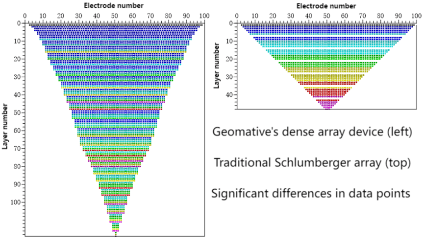
3. Main Components of a High-Density Electrical System
| Component | Function | Engineering Consideration |
|---|---|---|
| Electrical resistivity instrument | Controls current injection and voltage measurement | Confirm required measurement modes |
| Electrode converter | Automatically switches electrode combinations | Ensure compatibility with survey design |
| Multi-core cables | Connect instruments with electrodes | Cable condition affects data reliability |
| Electrodes | Transfer current into the ground | Contact resistance must be monitored |
| Data processing software | Converts measurements into resistivity models | Interpretation depends on inversion parameters |
A high-density electrical system improves acquisition efficiency by collecting large numbers of measurements through automated electrode switching.
However, higher data density does not automatically guarantee higher accuracy. Survey design, field conditions, and geological complexity remain critical factors.
Ⅲ. Resistivity Data Analysis and Interpretation
1. 2D Resistivity Profile Analysis
The original landfill investigation used a 2D resistivity profile to analyze underground electrical characteristics.、
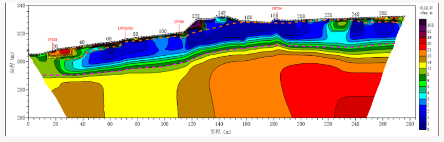
According to the original case interpretation, the resistivity profile was used to investigate:
- The approximate position of the landfill liner interface.
- The distribution characteristics of possible leachate zones.
- Electrical continuity beneath the investigated area.
The reported interpretation suggested that the resistivity distribution beneath the liner appeared relatively continuous and no obvious leakage-related anomaly was identified within the investigated section.
However, resistivity imaging provides indirect geological information.
A continuous resistivity boundary does not independently prove that a liner is completely intact.
Likewise, a low-resistivity anomaly does not automatically confirm leakage.
Interpretation should consider:
- Survey line spacing.
- Electrode configuration.
- Target depth.
- Geological background.
- Data quality.
- Inversion uncertainty.
For engineering decision-making, geophysical results should be combined with:
- Construction drawings.
- Historical landfill information.
- Groundwater monitoring.
- Direct inspection where necessary.
2. 3D Resistivity Model and Leachate Distribution Interpretation
The original investigation further developed a three-dimensional resistivity model to analyze spatial characteristics of interpreted low-resistivity zones.
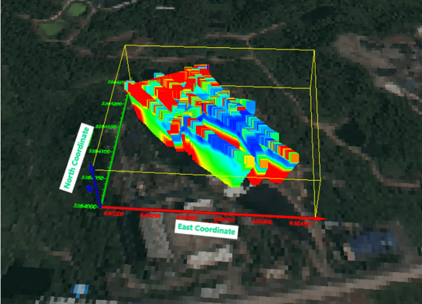
The 3D model provides a visual representation of how resistivity anomalies extend horizontally and vertically.
Based on previous physical-property information, the original case used 4 Ω·m as an interpretation boundary to distinguish possible leachate-rich areas.
This value should be understood as:
- A project-specific interpretation parameter.
- Based on local conditions.
- Used for visualization and analysis.
It should not be directly applied to other landfill sites.
Different landfill environments may show different resistivity responses due to:
| Influencing Factor | Effect on Resistivity |
|---|---|
| Soil composition | Clay and fine materials may reduce resistivity |
| Water content | Higher moisture generally decreases resistivity |
| Leachate chemistry | Dissolved ions may increase conductivity |
| Waste composition | Different waste materials create variable responses |
| Geological background | Natural formations may produce anomalies |
A reliable interpretation requires calibration with available site information.
3. Resistivity Model Interpretation Limitations
Although 3D resistivity models provide valuable spatial information, they are still inversion-based models.
The final image depends on:
- Measurement density.
- Electrode spacing.
- Data quality.
- Noise level.
- Inversion algorithm.
- Model constraints.
The model is therefore an interpretation of measured electrical responses rather than a direct underground photograph.
Engineers should avoid over-interpreting individual anomalies.
A responsible interpretation approach includes:
- Identify abnormal resistivity zones.
- Compare anomalies with geological information.
- Evaluate possible causes.
- Recommend targeted verification if required.
Ⅳ. Technical Advantages of High-Density Electrical Investigation for Landfills
1. Subsurface Resistivity Mapping
High-density electrical resistivity surveys provide spatial information about variations in subsurface electrical properties. In landfill investigations, these variations may help identify zones that warrant further examination for possible leachate accumulation or migration.
Compared with isolated point measurements, resistivity profiles can cover a larger portion of the investigated area. This can help engineers understand the continuity and geometry of electrical anomalies and determine where additional investigation may be needed.
However, the reliability of the interpretation depends on the electrical contrast between the target and surrounding materials. If the resistivity of the suspected leachate zone is similar to the background, the anomaly may be difficult to distinguish.
2. Integration of 2D Profiles and 3D Visualization
Two-dimensional resistivity profiles are useful for examining subsurface changes along individual survey lines. Three-dimensional models provide additional spatial context when the survey layout and data coverage support 3D interpretation.
| Investigation Method | Main Advantage | Typical Engineering Use |
|---|---|---|
| 2D resistivity imaging | Shows electrical variations along a survey line | Identifying anomalies and approximate interfaces |
| 3D resistivity modeling | Visualizes the spatial distribution of interpreted anomalies | Examining anomaly continuity and planning follow-up surveys |
| Geological and hydrological data integration | Helps distinguish competing explanations | Improving interpretation confidence |
| Independent verification | Tests whether the interpretation agrees with field evidence | Supporting environmental and engineering decisions |
The combination of these methods can improve the understanding of a landfill site, but model resolution remains dependent on survey geometry, electrode spacing, data quality, and inversion assumptions.
3. Support for Environmental Management
Resistivity investigation can support landfill management by identifying areas for closer examination. Depending on the results, the project team may use the interpreted anomalies to help plan:
- Additional groundwater sampling.
- Targeted drilling or direct investigation.
- Follow-up geophysical surveys.
- Leachate collection and monitoring activities.
- Further assessment of the liner system.
Geophysical surveys should be treated as part of a broader environmental investigation program rather than a substitute for required groundwater monitoring or direct verification.
4. Field Efficiency and Data Quality
Automated electrode switching allows high-density electrical systems to collect multiple measurement configurations efficiently. This can reduce some repetitive manual operations and provide a larger dataset for interpretation.
Nevertheless, the number of measurements alone does not determine survey quality. Field teams should inspect electrode contact, monitor electrical noise, document site conditions, and review data consistency during acquisition.
Ⅴ. Other Applications of High-Density Electrical Methods
Although this case focuses on landfill leachate investigation, high-density electrical methods can also support other engineering, environmental, and geological projects.
| Application | Investigation Objective | Potential Contribution of Resistivity Data |
|---|---|---|
| Landfill investigation | Assess leachate-related anomalies and subsurface electrical variations | Map possible conductive zones |
| Groundwater exploration | Investigate subsurface structures associated with groundwater | Identify electrical contrasts that may indicate water-bearing formations |
| Karst investigation | Examine possible cavities, fractured zones, and weathered rock | Identify anomalies relative to the surrounding formation |
| Engineering geology | Investigate geological boundaries and weathering profiles | Support subsurface structural interpretation |
| Soil salinity assessment | Examine spatial variations in electrical conductivity | Map zones potentially associated with elevated pore-water salinity |
| Dam and embankment investigation | Investigate possible seepage-related anomalies | Identify areas requiring further assessment |
These applications require different survey designs and interpretation criteria. For example, a low-resistivity zone in a landfill may be associated with conductive leachate, whereas a similar response in another setting could reflect clay-rich material or saline groundwater.
The interpretation must therefore be based on the geological setting, target characteristics, and available verification data.
Ⅵ. Equipment Selection and Survey Planning
Selecting a high-density electrical system for landfill investigation requires more than comparing instrument specifications. The equipment configuration and survey design should match the target, site conditions, and expected deliverables.
1. Define the Investigation Objective
Before selecting a system, determine whether the project aims to:
- Map possible leachate accumulation.
- Investigate potential migration pathways.
- Examine electrical characteristics near the liner.
- Establish a baseline for repeated monitoring.
- Identify areas for further direct investigation.
Different objectives may require different electrode layouts, line spacing, acquisition configurations, and interpretation strategies.
2. Consider Survey Depth and Electrode Spacing
Electrode spacing influences the depth of investigation and the level of detail that can be resolved. Wider spacing can increase investigation depth under suitable conditions but may reduce the resolution of smaller targets. Closer spacing can provide more detailed near-surface information, although the appropriate configuration depends on the target depth and survey geometry.
The survey plan should be designed around the expected dimensions of the anomaly rather than using a single spacing for every site.
3. Evaluate Site Access and Electrical Interference
Landfill surfaces may contain uneven terrain, cover materials, access roads, buried utilities, metallic structures, and other obstacles. These conditions can affect electrode placement and data quality.
Potential sources of electrical interference should be assessed before acquisition. The field team should also document areas where electrode contact is poor or where the planned array cannot be deployed as intended.
4. Establish Interpretation and Verification Criteria
The project team should define how anomalies will be identified and evaluated before final interpretation.
Recommended considerations include:
- Background resistivity measurements.
- Available geological and hydrogeological records.
- Historical leachate and groundwater monitoring data.
- Data-quality indicators.
- Inversion settings and model sensitivity.
- Requirements for independent verification.
A threshold such as the 4 Ω·m value used in the original case should be applied only when supported by the site’s physical-property information and investigation objectives.
5. Compare System Configurations
Geotech offers different WGMD-4 system configurations. The centralized and distributed systems should be evaluated against project-specific requirements rather than assumed to be interchangeable in every field situation.
| Selection Factor | Questions to Evaluate |
|---|---|
| Survey scale | How many survey lines and electrodes are required? |
| Acquisition workflow | Which electrode-switching and measurement modes are needed? |
| Site conditions | Are there access limitations, poor contact conditions, or electrical noise sources? |
| Data processing | What 2D or 3D interpretation outputs are required? |
| Field support | What training, technical documentation, and after-sales support are available? |
| Budget | What is the total project cost, including accessories, transport, fieldwork, and processing? |
The appropriate system is the one that meets the project’s technical requirements while providing a practical acquisition and interpretation workflow.
Ⅶ. Conclusion
The WGMD-4 high-density electrical method system was applied in the reported landfill investigation to examine subsurface resistivity characteristics associated with leachate distribution and the landfill liner interface. Together with the WDZS-3 multifunctional electrical water detector, the investigation used 2D resistivity profiling and 3D visualization to support interpretation of the surveyed area.
According to the original case report, the resistivity distribution beneath the interpreted liner interface appeared relatively continuous, and no obvious leakage-related anomaly was identified in the investigated section. The project also used 4 Ω·m as a site-specific interpretation threshold to help delineate possible leachate-rich zones in the 3D model.
These findings provide geophysical information that can support landfill environmental management, follow-up investigation, and monitoring planning. They should not be interpreted as conclusive proof that the entire landfill liner is intact or that no leakage exists outside the surveyed area.
For reliable decision-making, resistivity interpretation should be integrated with geological and hydrological information, construction records, environmental monitoring results, and independent verification where appropriate.
The case illustrates how high-density electrical methods can contribute to landfill investigation by providing spatial subsurface information that complements conventional environmental and engineering assessment.
Related Articles
| Title | Core Content | URL |
|---|---|---|
| WGMD-4 High-Density Electrical System | Product specification page for WGMD-4 high-density resistivity survey system | https://geotechcn.net/products/electrical-instrument/wgmd-4-centralized-system/ |
| ERT Instruments: Electrical Resistivity Tomography Guide | Complete technical guide to ERT and high-density resistivity instruments | https://geotechcn.net/service/ert-instruments/ |
| Resistivity Surveying Techniques Guide | Comprehensive guide to DC resistivity and high-density array methods | https://geotechcn.net/service/resistivity-surveying-techniques/ |
| ERT and TDIP Geophysical Survey Technologies | Guide to geoelectrical monitoring for environmental and containment sites | https://geotechcn.net/service/ert-tdip-geophysical-survey/ |
| Geophysical Methods: ERT Guide | Full guide to subsurface investigation including landfill applications | https://www.epa.gov/environmental-geophysics/electrical-resistivity |
Reference Sources
| Title | Core Content | URL |
|---|---|---|
| US EPA — Electrical Resistivity | Explain resistivity principles, apparent resistivity and inversion | https://www.epa.gov/environmental-geophysics/electrical-resistivity |
| ASTM D6431-25 — Direct Current Resistivity Method | Reference standard guidance for DC resistivity site investigation | https://store.astm.org/standards/d6431 |
| US EPA — Time-Domain Electromagnetic Methods | Optional background on complementary geophysical methods | https://www.epa.gov/environmental-geophysics/electromagnetic-methods-time-domain |
FAQ
Q1: What is the high-density electrical method in geophysics?
The high-density electrical method is an advanced array-based DC resistivity technique integrating depth sounding and lateral profiling. It uses dense electrode arrays and automated multi-configuration measurements to produce high-resolution 2D subsurface resistivity images. The method delivers decimeter-scale near-surface resolution for detailed subsurface characterization.
Q2: How does the method detect landfill leachate?
Leachate has high dissolved solids content that produces characteristically low electrical resistivity compared to drier waste and soil. High-density resistivity surveys map these low-resistivity zones to define leachate distribution. A calibrated resistivity threshold of 4 Ω·m was used in this study to delineate fully saturated zones and estimate total leachate volume.
Q3: Can electrical surveys detect geomembrane liner damage?
Yes, intact geomembranes produce a distinct high-resistivity interface in resistivity profiles. Breaches or defects create localized low-resistivity anomalies where leachate crosses the liner boundary. High-density arrays can resolve small discontinuities that conventional methods would miss, providing early warning of developing liner issues.
Q4: What advantages does high-density have over conventional resistivity?
High-density electrical methods provide much higher spatial resolution, denser data coverage and automated multi-configuration acquisition compared to conventional resistivity. This enables detection of smaller features, continuous profile coverage and more efficient field operation. It is particularly valuable for detailed near-surface investigations like liner integrity assessment.
Q5: How deep can high-density electrical surveys investigate?
High-density electrical methods are optimized for near-surface investigation, typically reaching up to approximately 100 meters maximum depending on array spacing and ground conductivity. Depth is shallower than conventional deep sounding but with much higher resolution. The method is optimized for detailed characterization of the upper tens of meters.
FAQ
What is the main difference between a single tap and a double tap?
The double tap has a large current and can be used for IP testing to get more accurate data.
What is the principle of high-density electrical prospecting?
High-density apparent resistivity method is an array prospecting method, also known as automatic apparent resistivity system, which is developed from direct current method. Its function is equivalent to the combination of quadrupole sounding and electrical profiling method. The artificial electric field is formed by supplying electricity to the underground through electrodes. The distribution of the electric field is closely related to the distribution of the resistivity of the underground rock and soil medium. By measuring the artificial electric field at different parts of the surface, the distribution of the apparent resistivity of the underground medium is understood, and the underground geological structure is inferred and interpreted based on the distribution of the apparent resistivity of the rock and soil medium.
What are the advantages of high-density electrical method?
The principle of high-density electrical method is the same as that of traditional resistivity method. It is a combination method of multiple devices and multiple pole distances that integrates electrical depth sounding and electrical profiling method, which can obtain the conductivity characteristics of two-dimensional underground media. It has the characteristics of multi-device data acquisition in one pole arrangement, and highlighting abnormal information by obtaining ratio parameters, which greatly increases the amount of collected data, improves work efficiency, and ensures the accuracy and reliability of the pole running process.
This method is particularly sensitive to the water content of the surrounding rock. If the surrounding rock is broken and contains water, its apparent resistivity is significantly reduced. The apparent resistivity of intact and hard rock and soil is significantly higher than that of the surrounding rock in the fault zone or broken zone and water-rich zone. This method has a clear principle and intuitive images. It is a geophysical method with high resolution. In recent years, with the improvement of computer data acquisition technology, the exploration efficiency has been greatly improved, the coverage area and detection depth of the profile have been increased, reliable data can be obtained in a strong interference environment, the signal-to-noise ratio has been greatly improved, and the geological body can be accurately detected. This method has been widely and successfully applied in engineering and hydrogeological exploration and exploration of mineral and water resources.
In what fields is the high-density electrical method generally used?
(1) Application in coalfield and mine goaf detection
(2) Non-destructive detection of termite nests in dam foundations
(3) Karst and foundation surveys of railways, roads and tunnels
(4) Delineation of stratum lithology boundaries
(5) Survey of the leakage range of landfills
(6) Ancient tomb surveys
(7) Detection of sewage pipes
(8) Non-destructive testing of leakage in reservoirs and river dams
(9) Detection of bedrock fracture zones
(10) Soil salinity and water quality surveys
(11) Detection of ancient tunnels, air-raid shelters, metal burial sites, etc.
What are the application characteristics of high-density electrical method?
(1)The high-density resistivity method is based on the resistivity method, so it is suitable for all underground explorations with obvious conductivity differences;
(2)Any medium underground will have a weak polarization potential at the moment of power on and off, which will affect our measurement of the true potential difference. When the electrode distance is small, the loop current is large, which has little effect on the measurement results; when the electrode distance is too large, the interference potential is close to the effective potential, which has a greater impact on the measurement results. Therefore, due to the influence of the power supply electrode distance, the exploration depth cannot be too large, generally within 100m. When the conductivity of the soil medium is good, it can be appropriately increased, and the exploration depth in the soil medium with poor conductivity is appropriately smaller;
(3)It is generally less used in cities, near large transmission lines, etc. due to site restrictions and industrial stray current interference; 4. In areas such as concrete pavements and exposed bedrock surfaces, it is also less used due to the difficulty of electrode layout.