Welcome to Geotech!
-1.png)


ERT & TDIP: Principles and Landfill 丨ERT and TDIP for Landfill Monitoring
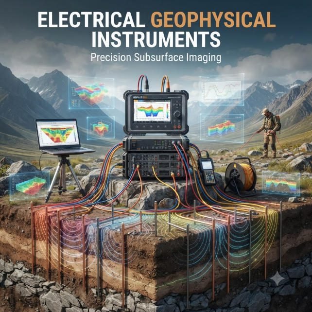
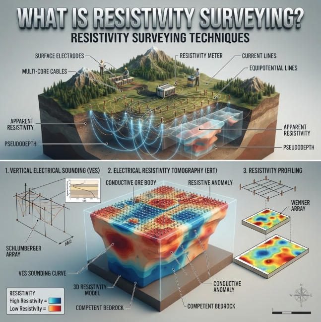
Overview:Electrode arrays define how current enters the ground and how electrical potential differences are measured. Understanding Electrode Arrays helps survey teams design reliable Electrical Resistivity Tomography (ERT) investigations. This guide explains common configurations, geometric factors, depth sensitivity, and field limitations. It also compares Electrode Arrays for groundwater, engineering, and environmental studies, helping professionals select Electrical Resistivity Tomography (ERT) methods that match geological conditions and project objectives.
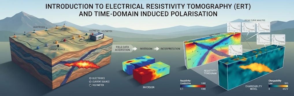
Comparative Analysis of Geophysical Survey Technologies
| Technical Attributes | Electrical Resistivity Tomography (ERT) | Time-Domain Induced Polarization (TDIP/IP) |
|---|---|---|
| Core Property Parameters | Resistivity ρ (Ω·m) Measures material’s resistance to electric current | Chargeability ma (mV/V) Quantifies polarization energy storage capacity |
| Sensitivity Indicators | Moisture/fluid content, porosity, salinity, lithology | Clay minerals, metallic deposits, plastic contaminants, lithological features |
| Data Acquisition | Stainless steel electrode arrays High-density configurations (e.g., 110 electrodes at 0.75m spacing) | Bipolar current pulses (2s injection + 2s decay monitoring) Dipole-dipole array (n≤6) |
| Resolution Limitations | Depth-dependent signal attenuation Requires inversion model validation | Rapid signal decay impacts deep-layer data Demands rigorous noise filtering and quality control |
Key Environmental Engineering Applications
1. Landfill Characterization
ERT/IP integration enables precise identification of:
- 3D contaminant plume mapping
- Impermeable liner integrity assessment
- Leachate migration pathways
- Metallic/plastic waste localization
2. Hydrogeological Investigations
- Groundwater contamination monitoring (salinization/organic pollutants)
- Aquifer structure imaging
- Geotechnical anomaly detection (karst cavities/fracture networks)
3. Mineral Resource Exploration
- Sulfide deposit localization
- Clay mineral distribution mapping
- Industrial plastic waste identification
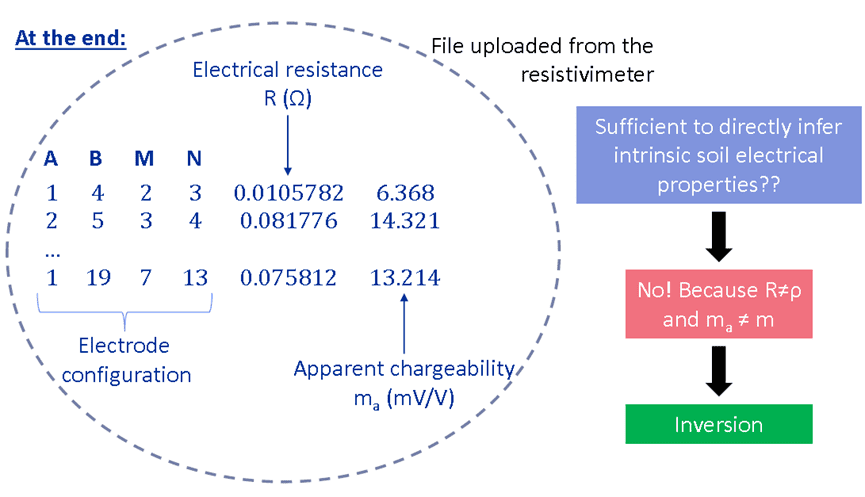
Principles: Data acquisition
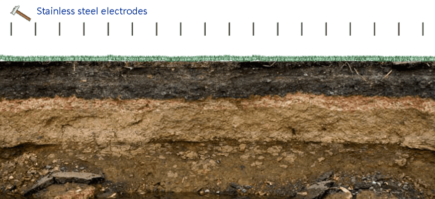
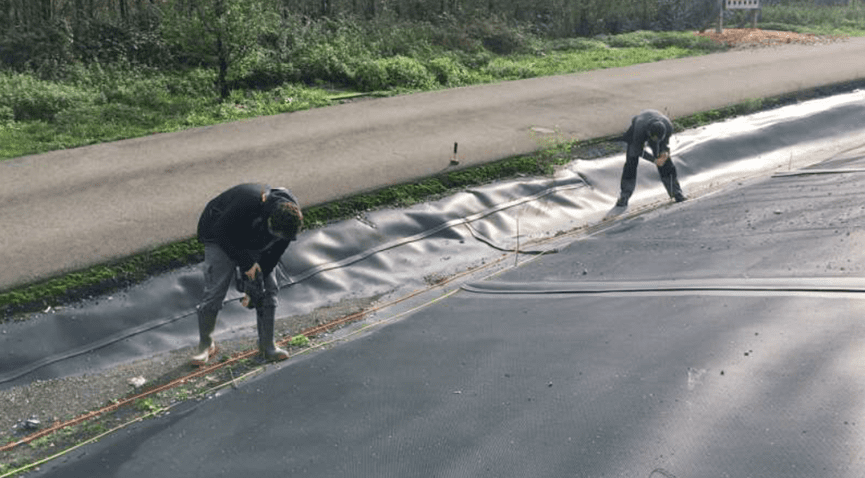
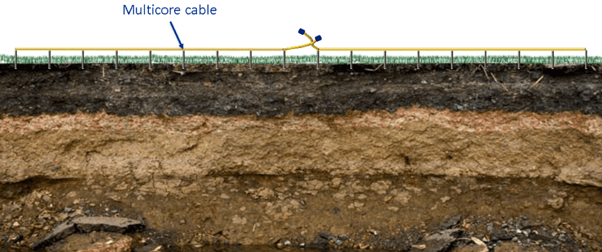
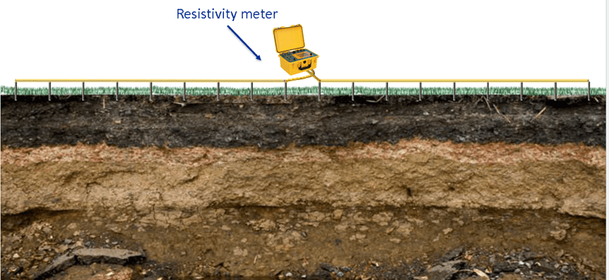
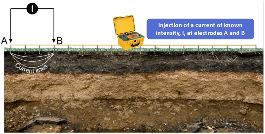

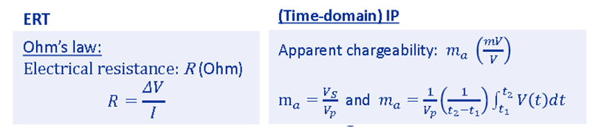

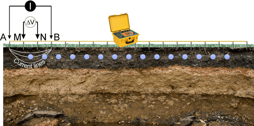
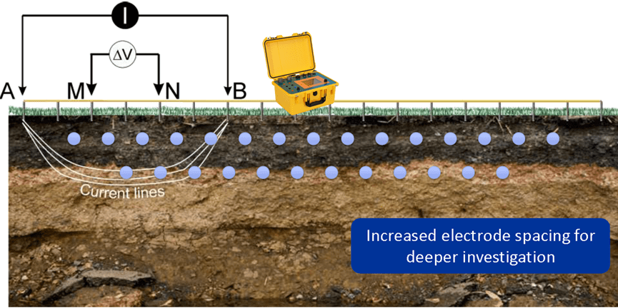
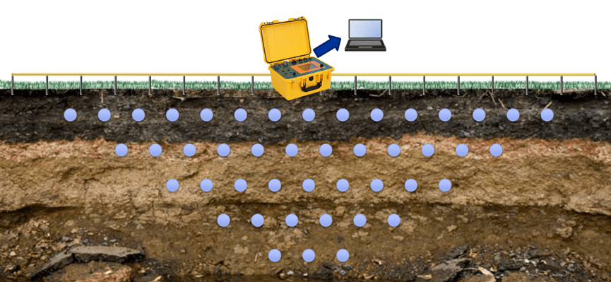
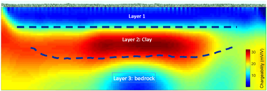
- Detection of 3 layers with contrasting electrical properties
- Loss of resolution in depth and on the edges of the model
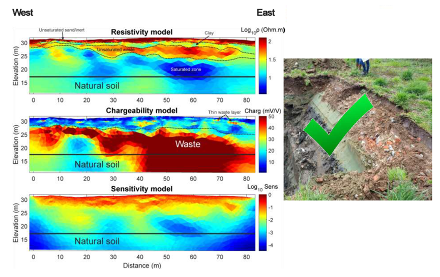
- Like all “surface” geophysical methods, ERT and IP suffer from limited depth of investigation and loss of resolution with depth
- Very important to ensure good quality of data and to quantify it
- Always appraise the reliability of models
Pre-investigation design, feasibility and appraisal studies should always be conducted to test different survey conditions and configurations
Case Sturdies
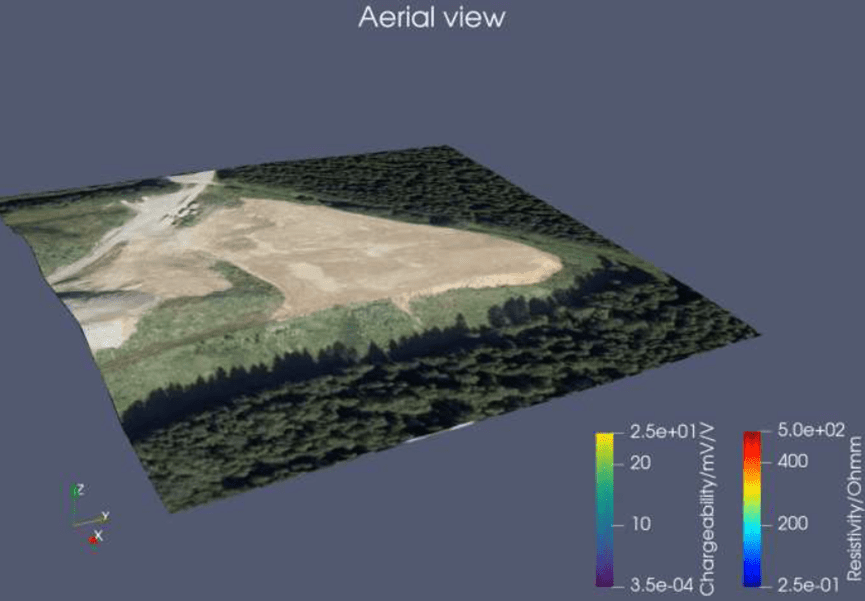
Landfill characterization

ERT and IP profile:
• 110 electrodes spaced by 0.75 m
• Electrical current injection was setup to 2 s (delay of 0.8 s and acquisition of 1.2 s) and voltage decay was measured for 2 s after current shut down
• Dipole-Dipole with ‘n’ factor limited to 6
Conclusions
Summary of application on landfills
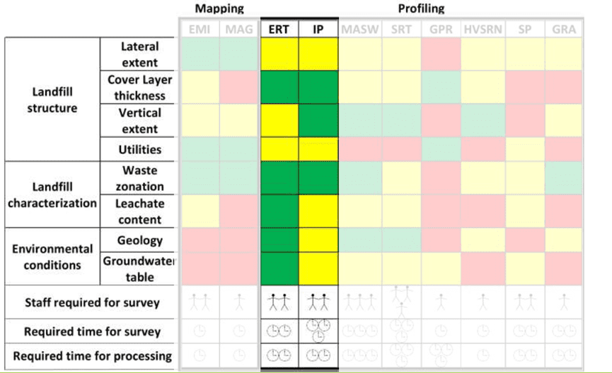
| ERT | IP | |
| Advantages | • Simple and robust • High variability of electrical resistivity • Cost-effective • Sensitive to water content • 2D, 3D and 4D images | • Detection of disseminated minerals • Sensitive to clay and metal particles/objects • Potential for quantification • 2D, 3D and 4D images |
| Disadvantages | • Non-unicity • Non-trivial modelling • Geological overlap | • Same disadvantages as ERT • Electrochemical phenomena are not yet well understood • IP measures are slower and more expensive than ERT measures. |
Related Articles
| Title | Core Content | URL |
|---|---|---|
| Resistivity Survey Methods and ERT Guide | Resistivity survey methods, array configurations, and field selection | https://geotechcn.net/service/resistivity-surveying-techniques/ |
| What Is Electrical Resistivity Tomography (ERT)? | ERT principles, electrode arrangements, and subsurface imaging | https://geotechcn.net/service/what-is-electrical-resistivity-tomography/ |
| ERT Geophysics: Principles, Arrays & Field Applications | ERT principles, array sensitivity, and practical applications | https://geotechcn.net/service/ert-geophysics-principles/ |
| What is Vertical Electrical Sounding (VES)? | Schlumberger and Wenner configurations for vertical sounding | https://geotechcn.net/service/what-is-vertical-electrical-sounding-ves/ |
| High-Density Resistivity: ERT System & Applications | High-density resistivity acquisition and electrode configurations | https://geotechcn.net/service/high-density-resistivity-20250301/ |
| Geophysical Methods: Electrical Resistivity Tomography (ERT) | Electrode geometry, apparent resistivity, and ERT survey methods | https://geotechcn.com/service/geophysical-methods-ert-guide/ |
Reference Sources
| Title | Core Content | URL |
|---|---|---|
| Electrical Resistivity — US EPA | Electrical resistivity principles, apparent resistivity, electrode arrays, and depth of investigation | https://www.epa.gov/environmental-geophysics/electrical-resistivity |
| A Numerical Comparison of 2D Resistivity Imaging with 10 Electrode Arrays | Numerical comparison of electrode-array resolution and imaging performance | https://onlinelibrary.wiley.com/doi/10.1111/j.1365-2478.2004.00423.x |
| Comparative Tests on Different Multi-Electrode Arrays Using Models in Near-Surface Geophysics | Array comparison using synthetic models and field surveys | https://academic.oup.com/jge/article/6/1/1/5127399 |
| Induced Polarization (IP) and Complex Resistivity — US EPA | IP acquisition, electrode configurations, and signal-quality considerations | https://www.epa.gov/environmental-geophysics/induced-polarization-ip-and-complex-resistivity |
| Investigating the Performance of Electrical Resistivity Arrays | Technical study of common DC resistivity arrays and their performance | https://vtechworks.lib.vt.edu/server/api/core/bitstreams/86b27899-05e2-4882-b31b-22e8b468d8d6/content |
FAQ
Q1. What is an electrode array in geophysics?
An electrode array is a defined arrangement of electrodes used to inject electrical current and measure voltage differences in the ground. Its geometry determines the geometric factor and influences subsurface sensitivity. Engineers use different arrays to investigate geological layering, faults, groundwater-bearing formations, and environmental anomalies through resistivity surveys.
Q2. What is the difference between Wenner and dipole-dipole arrays?
The Wenner array uses four equally spaced electrodes and often provides strong voltage signals. The dipole-dipole array separates current and potential dipoles, making it useful for investigating lateral resistivity changes. Engineers select between them according to target geometry, noise conditions, and required resolution.
Q3. Which electrode array is best for groundwater exploration?
No electrode array is universally best for groundwater exploration. Wenner-Schlumberger and Schlumberger configurations can support investigations of layered formations, while dipole-dipole measurements may help identify lateral structures. The final design depends on geology, target depth, groundwater conditions, and independent hydrogeological evidence.
Q4. How does electrode spacing affect investigation depth?
Larger electrode separations generally increase sensitivity to deeper regions, while smaller spacing supports denser sampling of shallow structures. However, spacing does not determine depth by itself. Array geometry, profile length, subsurface resistivity, noise, and inversion sensitivity all influence the effective depth of investigation.
Q5. Can different electrode arrays be combined in one ERT survey?
Yes. Hybrid acquisition combines multiple array configurations to improve measurement coverage and sample different sensitivity patterns. It can be useful in complex geological settings. However, combining arrays does not guarantee better results. Engineers must evaluate data quality, survey geometry, acquisition efficiency, and inversion stability.