Welcome to Geotech!
-1.png)


ERT Geophysics: Principles, Arrays & Field Applications 2026
TIPS:ERT geophysics maps subsurface structures by measuring how earth materials resist electrical current. This guide explains the core principles of ERT geophysics, from Ohm’s Law to electrode array design, and how modern systems like Geotech GIM deliver high-resolution images for mining, environmental, and engineering projects.
Ⅰ. ERT as a Discipline in Modern Geophysics
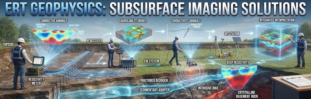
Electrical resistivity tomography sits at the intersection of physics, geology, and engineering. It belongs to the broader field of applied geophysics. Its goal is simple: map how rocks and soils conduct electricity. The result reveals structures hidden below ground.
ERT geophysics measures resistivity. Resistivity is the inverse of conductivity. It describes how difficult it is for current to pass through a material. Clay has low resistivity. Granite has high resistivity. Water-saturated sand sits in between. These differences create the contrast that ERT detects.
The method is non-invasive. No drilling is needed. Electrodes placed on the surface or in boreholes do all the work. A typical survey covers large areas in a single day. This makes ERT geophysics one of the most cost-effective tools in the geophysical toolkit.
ERT extends traditional DC resistivity sounding. Early methods used four electrodes at a single point. They produced 1D vertical profiles. Modern ERT uses dense arrays. It creates 2D cross-sections or 3D volumes. This jump from 1D to 3D transformed how geophysicists interpret the subsurface.
Ⅱ. The Physics: Ohm’s Law in the Earth
1.The Fundamental Equation
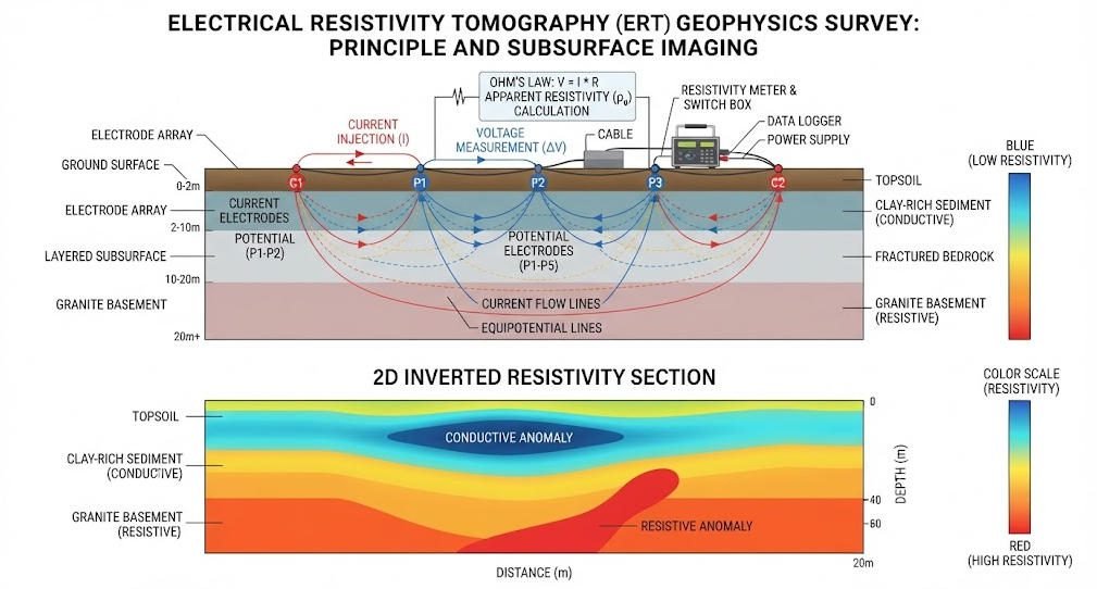
ERT geophysics relies on Ohm’s Law. Current flows into the ground through two electrodes. Voltage is measured across two other electrodes. The instrument calculates resistance:
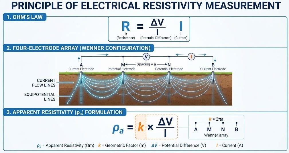
R = ΔV / I
Where R is resistance, ΔV is voltage difference, and I is current. But resistance alone does not describe the ground. Electrode spacing and geometry also matter.
Apparent resistivity adds the geometric factor:
ρa = k × ΔV / I
Where ρa is apparent resistivity and k is the geometric factor. The value of k depends on the electrode array type. For a Wenner array, k equals 2πa. For a Schlumberger array, k depends on the inner and outer electrode spacing.
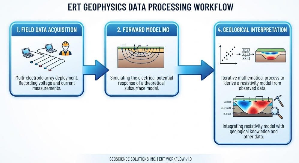
Apparent resistivity is not true resistivity. It is a weighted average of all materials between the electrodes. Inversion software converts apparent resistivity into true resistivity models. This is the core computational step in ERT geophysics.
2.What Controls Subsurface Resistivity?
Many factors affect resistivity values. Understanding them helps interpreters avoid false conclusions.
- Porosity and saturation: Water-filled pores conduct current. Dry pores resist it. A fully saturated sandstone may show 50 Ω·m. The same sandstone dry may show 1,000 Ω·m.
- Clay content: Clay minerals conduct electricity through ion exchange. Clay layers often show resistivity below 20 Ω·m.
- Salinity: Dissolved salts increase conductivity. Saltwater shows resistivity below 5 Ω·m. Freshwater shows values above 100 Ω·m.
- Temperature: Warm water conducts better than cold water. A 10°C rise can halve resistivity.
- Ore minerals: Metallic sulfides are conductive. They create strong low-resistivity anomalies.
- Weathering: Weathered rock is more porous and conductive than fresh rock. This contrast helps map weathering profiles.
Ⅲ. Electrode Arrays: The Geometry of Detection
The choice of electrode array shapes what ERT geophysics can see. Each array has a unique sensitivity pattern.
Wenner Array: Four equally spaced electrodes. Current flows through the outer pair. Voltage measures across the inner pair. This array offers excellent vertical resolution. It is ideal for layered geology and groundwater surveys. The geometric factor is simple: k = 2πa.
Schlumberger Array: Inner potential electrodes stay fixed. Outer current electrodes expand. This array reaches deeper with less cable. It is the standard for deep bedrock mapping. The geometric factor is k = π(AB² – MN²) / 2MN, where AB is the outer spacing and MN is the inner spacing.
Dipole-Dipole Array: Paired current electrodes and paired potential electrodes. This array detects lateral changes well. It maps steeply dipping faults and vertical fractures. However, signal strength drops faster with depth than Wenner.
Pole-Dipole Array: One remote current electrode and a dipole potential pair. This array offers asymmetric coverage. It is useful when space is limited on one side of the survey line.
Geotech’s GIM Series supports all standard arrays. It also runs combined sequences. A single deployment captures both Wenner and Schlumberger data. This reduces field time and improves model reliability.
Ⅳ. From Data to Geology: The Inversion Challenge
1.The Non-Uniqueness Problem
ERT geophysics faces a fundamental challenge. Multiple subsurface models can produce the same surface data. This is called non-uniqueness. A low-resistivity zone could be clay, water, or ore. A high-resistivity zone could be granite, dry sand, or an air-filled cavity.
Inversion algorithms solve this by adding constraints. Smoothness-constrained inversion (Occam’s algorithm) favors gradual changes. It produces geologically realistic models. Structure-coupled inversion uses L1-norm regularization. It sharpens boundaries. This helps distinguish cavities from layers.
Borehole data breaks non-uniqueness. A single drill log calibrates the entire resistivity model. Always integrate ERT with ground truth.
2.Forward Modeling for Survey Design
Forward modeling predicts data before fieldwork. You define a hypothetical subsurface. Software calculates the apparent resistivity response. This tests whether your array can resolve the target.
If the predicted response is weak, you adjust electrode spacing or array type. This saves costly field rework. Tools like RES2DMOD handle 2D models. COMSOL Multiphysics handles complex 3D geometry.
Ⅴ. Survey Modes in ERT Geophysics
1.Surface ERT
Surface ERT is the most common mode. Electrodes deploy in a line or grid. The instrument auto-switches pairs. This mode works best on flat or gently sloping terrain. Slopes above 15° distort current flow. Terrain correction algorithms fix mild slopes.
A California gold project used surface ERT with the WGMD-10X. Crews laid 1,200 electrodes across a slope. The 6 A transmitter penetrated 300 m. Inversion revealed an 800 m low-resistivity zone. Drilling verified gold vein thickness with errors below 8%.
2.Cross-Hole ERT
Cross-hole ERT places electrodes in boreholes. It overcomes surface obstacles. It reaches beneath buildings, roads, and steep terrain. This mode demands non-polarizable Ag/AgCl electrodes. Standard steel electrodes polarize and distort IP measurements.
A European landfill used cross-hole ERT. Electrodes in multiple boreholes surrounded the waste cell. 3D inversion mapped conductive plumes escaping the liner. Resolution reached 0.3 m. Surface arrays achieved only 1.2 m.
3.Underwater ERT
Underwater surveys map riverbeds and coastal zones. Electrodes mount on a cable dragged across the sediment. Waterproof cables and connectors are essential. Geotech’s marine-compatible systems use IP68-rated TPU cables. They operate at depths up to 100 m.
Ⅵ. Applications Across Geophysical Disciplines
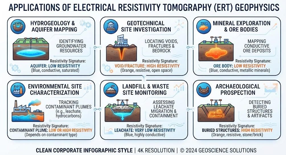
ERT geophysics serves diverse industries. Here are the primary fields.
| Discipline | Target | Resistivity Signature | ERT Value |
|---|---|---|---|
| Hydrogeology | Aquifer boundaries | High-resistivity freshwater | Delineates water table and salinity |
| Environmental | Contaminant plumes | Very low-resistivity leachate | Tracks migration without drilling |
| Mining | Ore bodies | Low-resistivity sulfides | Maps alteration zones and structures |
| Engineering | Voids and faults | High or low anomalies | Assesses foundation stability |
| Archaeology | Buried structures | Anomalous contrasts | Non-invasive site mapping |
| Geothermal | Reservoir zones | Low-resistivity hot fluids | Identifies productive fractures |
Each discipline demands specific array selection. Hydrogeology favors Wenner arrays. Mining often needs IP-integrated surveys. Archaeology uses fine 1–2 m spacing for high resolution.
Ⅶ. Data Quality: What Field Geophysicists Must Control
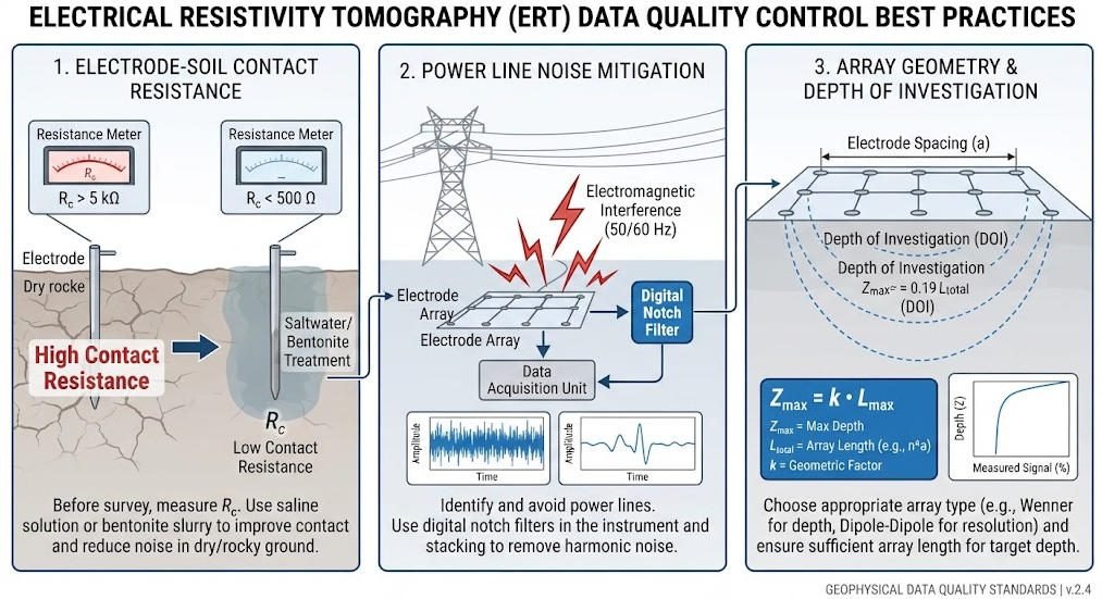
Quality ERT data does not happen by accident. Three factors control it.
Electrode contact resistance: Values above 2 kΩ weaken signals. Solutions include saltwater, bentonite gel, or deeper electrode penetration. Parsekian et al. found that 2.6 kΩ contacts produced 2–3× higher stacking errors than 1.1 kΩ contacts.
Noise sources: Power lines, metal fences, and buried cables create interference. The 50/60 Hz hum from power lines is the most common culprit. Survey at night or use notch filters to suppress it.
Array geometry: Electrode spacing must match target size. A rule of thumb: maximum depth equals one-third to one-fifth of total array length. A 150 m array reaches 30–50 m. For deeper targets, expand the array or switch to cross-hole mode.
Ⅷ. Modern ERT Hardware: The Geotech GIM Series
The GIM Series represents the current state of ERT geophysics. It integrates resistivity, induced polarization, and self-potential in one platform.
Key specifications:
- 24-bit A/D conversion for 0.3% measurement accuracy
- 10-channel synchronous acquisition
- Bidirectional cascade for unlimited line extension
- IP67 housing for -20°C to +60°C operation
- 1,500 m depth penetration with high-voltage modules
The GIM-10 system handles complex 3D surveys. The WGMD-10X adds rolling measurement and underwater modes. Both export data to RES2DINV, EarthImager, and industry-standard formats.
Related Articles
Explore related Geotech resources for your geophysical projects:
- What Is Electrical Resistivity Tomography? Complete ERT Guide
- ERT Instruments: A Comprehensive Guide
- What Is ERT Geophysics?
- 2D vs 3D Electrical Resistivity Imaging Methods
- ERT vs TEM: Which Geophysical Method Fits Your Project?
- Underground Electrical Exploration Methods Compared
- Comparative Study: HDR, DC Sounding & ERT
- Induced Polarization Method for Mineral Exploration
- Geophysical Exploration Classification & Applications
- GIM Series Intelligent Resistivity & IP Meter
Reference Sources
| Authority | Source URL |
|---|---|
| U.S. Environmental Protection Agency (EPA) — Electrical Resistivity | https://www.epa.gov/environmental-geophysics/electrical-resistivity |
| CLU-IN — Electrical Resistivity Tomography Technology Overview | https://clu-in.org/characterization/technologies/default2.focus/sec/Geophysical_Methods/cat/Electrical_Resistivity_Tomography/ |
| Society of Exploration Geophysicists (SEG) | https://seg.org/ |
| Nature — ERT for Rock Mass Quality Evaluation | https://www.nature.com/articles/s41598-021-03217-8 |
| Geotech Instrument Co., Ltd. — ERT Geophysics Guide | https://geotechcn.net/service/what-is-ert-geophysics/ |
FAQ
Q1: What is ERT geophysics and how does it differ from standard geophysical surveys?
A: ERT geophysics is a branch of applied geophysics that uses electrical resistivity to image subsurface structures. Unlike seismic surveys that measure elastic waves, ERT measures how materials conduct electricity. It is non-invasive, cost-effective, and excels in conductive environments where seismic methods struggle.
Q2: How does Ohm’s Law apply to ERT geophysics in the field?
A: Ohm’s Law (R = ΔV / I) is the foundation of every ERT measurement. Current electrodes inject known current into the ground. Potential electrodes measure the resulting voltage. The geometric factor converts resistance into apparent resistivity. Inversion software then converts apparent resistivity into true geological models.
Q3: What electrode array is best for groundwater exploration in ERT geophysics?
A: The Wenner array is the standard choice for groundwater surveys. It provides excellent vertical resolution. It clearly shows aquifer boundaries and water table depth. For deep aquifers beyond 100 m, the Schlumberger array reaches deeper with less cable.
Q4: Why is ERT geophysics data considered non-unique?
A: Non-uniqueness means multiple subsurface models can produce the same surface measurements. A low-resistivity anomaly could be clay, water, or ore. Geophysicists solve this by adding geological constraints, using multiple arrays, and integrating borehole data for calibration.
Q5: What is the maximum depth ERT geophysics can achieve?
A: Standard surface ERT reaches 0.5 to 300 m. Depth equals roughly one-third to one-fifth of total electrode array length. Cross-hole ERT extends deeper using borehole electrodes. Geotech’s GIM Series with high-voltage modules achieves 1,500 m in favorable conditions.