Welcome to Geotech!



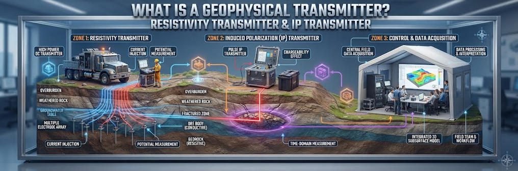
What Is A Geophysical Transmitter?Resistivity Transmitter & IP Transmitter
Overview:A High Power IP Transmitter injects controlled electrical energy into the ground for demanding induced polarization surveys. An Induced Polarization Transmitter supports polarization measurements, while a Resistivity Transmitter supplies current for subsurface resistivity surveys. This guide explains their principles, system components, output specifications, field applications, and practical selection criteria.
Ⅰ. What Is a High Power IP Transmitter?
1. Definition and Primary Function
A High Power IP Transmitter is a geophysical electrical source that delivers controlled electrical energy through ground electrodes to support induced polarization measurements under demanding survey conditions.
Its primary functions include:
- Generating controlled electrical output.
- Regulating or controlling output current and voltage.
- Producing the waveform required by the survey method.
- Supporting stable electrical injection.
- Providing output and operating-status information.
- Working with a compatible receiver and electrode system.
The transmitter establishes the electrical field. The receiver measures the resulting voltage response. Processing software then converts the measurements into apparent resistivity, chargeability, or other survey-specific parameters.
2. Why High Power Matters
High-power transmission can be useful when ground resistance, electrode spacing, or survey geometry creates demanding electrical injection requirements.
However, higher power does not automatically produce better data or greater investigation depth.
The actual result depends on:
- Geological conditions.
- Electrode configuration.
- Ground contact resistance.
- Receiver sensitivity.
- Environmental noise.
- Signal timing and stability.
- Survey design and interpretation.
The engineering objective is to provide sufficient electrical output while maintaining reliable measurements and safe operation.
Ⅱ. What Is an Induced Polarization Transmitter?
1. Definition and Measurement Objective
An Induced Polarization Transmitter is a transmitting device designed to support the electrical excitation required for induced polarization surveys.
IP measures how subsurface materials polarize under an applied electrical field and how their electrical response changes over time or frequency.
When current passes through geological materials, electrical charges can accumulate at mineral-fluid interfaces and other boundaries. After the applied field changes or disappears, the resulting electrical response may persist for a measurable period.
This response provides information about subsurface polarization behavior. It can complement resistivity measurements in mineral exploration and other investigations. The U.S. EPA describes these processes and distinguishes time-domain, frequency-domain, and spectral IP methods.
2. Time-Domain IP
Time-domain induced polarization (TDIP) applies a controlled current for a defined interval and then interrupts or reverses it.
The receiver records the voltage response during the subsequent decay period or during a specified measurement window.
A simplified sequence is:
Current ON → Charge polarization → Current OFF → Voltage decay → IP measurement
The transmitter must support the waveform and timing required by the measurement system.
3. Frequency-Domain IP
Frequency-domain induced polarization (FDIP) uses time-varying electrical signals at selected frequencies.
The measurement system evaluates changes in amplitude and phase between the transmitted and received signals.
This method can provide information about the frequency-dependent electrical response of the subsurface.
4. Spectral IP
Spectral induced polarization (SIP) evaluates electrical responses across a range of frequencies.
It can help characterize frequency-dependent polarization behavior. The method requires appropriate signal generation, receiver capability, and processing.
Not every IP Transmitter supports every IP measurement mode. Buyers should verify the instrument’s documented capabilities.
Ⅲ. What Is a Resistivity Transmitter?
1. Definition and Primary Function
A Resistivity Transmitter is an electrical source that injects controlled current into the ground for resistivity surveys.
The survey measures the resulting potential difference and uses electrode geometry to calculate apparent resistivity.
A simplified electrode arrangement consists of:
- Current electrodes A and B.
- Potential electrodes M and N.
- A transmitter that injects current.
- A receiver that measures voltage.
For a general electrode configuration:
ρa = K × V / I
Where:
- ρa = apparent resistivity.
- K = geometric factor.
- V = measured potential difference.
- I = injected current.
The geometric factor depends on electrode positions and the array configuration.
2. Resistivity Measurement vs. IP Measurement
Resistivity surveys primarily evaluate the relationship between injected current and measured voltage.
IP surveys investigate additional polarization-related responses. They may collect resistivity and IP data during the same acquisition program.
The methods share much of the field setup, but IP requires appropriate measurement timing or frequency control. The EPA notes that IP data can be collected using electrode configurations similar to those used for resistivity surveys, although IP acquisition and interpretation can be more demanding.
Ⅳ. High Power IP Transmitter vs. Resistivity Transmitter
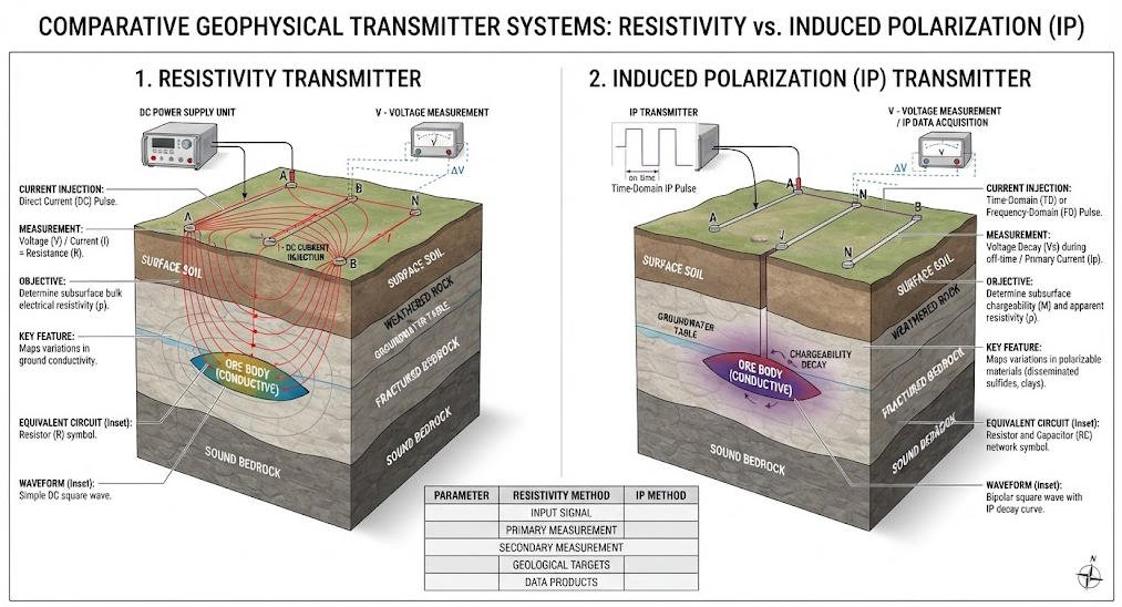
The terms High Power IP Transmitter, Induced Polarization Transmitter, Resistivity Transmitter, and IP Transmitter are related, but they are not exact synonyms.
| Feature | High Power IP Transmitter | Induced Polarization Transmitter | Resistivity Transmitter | IP Transmitter |
|---|---|---|---|---|
| Main emphasis | High-output IP transmission | IP measurement support | Resistivity current injection | IP measurement support |
| Electrical injection | Yes | Yes | Yes | Yes |
| Resistivity measurement | Often supported | May be supported | Primary purpose | May be supported |
| IP measurement | Primary purpose | Primary purpose | Not necessarily | Primary purpose |
| Output requirements | Depends on survey demand | Depends on method | Depends on survey demand | Depends on method |
| Timing requirements | Important for IP modes | Important | Depends on method | Important for IP modes |
| Typical application | Demanding IP and combined surveys | Mineral and geological surveys | ERT, groundwater, engineering | IP surveys and related resistivity work |
The key distinction is functional rather than purely commercial. A transmitter’s actual capabilities depend on its electrical architecture and supported measurement modes.
Ⅴ. How Does an IP Transmitter Work?
1. Power Supply
The transmitter receives energy from a suitable power source.
Depending on the system, this may involve:
- An internal battery.
- An external DC power source.
- A generator.
- An integrated power module.
The power supply must support the intended operating mode within the manufacturer’s limits.
2. Power Conversion and Output Control
The transmitter converts the available energy into an electrical output suitable for ground injection.
Its control system may regulate current, voltage, or both within a defined operating range.
The available output depends on the power source, circuit resistance, and instrument limits.
3. Ground Current Injection
The transmitter delivers current through current electrodes.
The injected current creates an electrical field in the subsurface. Geological materials respond according to their electrical properties.
4. Measurement of the Geological Response
The receiver measures the voltage response across potential electrodes.
For resistivity surveys, the measured voltage and injected current are combined with the geometric factor to calculate apparent resistivity.
For IP surveys, the system also measures the polarization-related response according to the selected method.
5. Data Processing
The acquisition system records the measurements and applies the relevant processing workflow.
Depending on the survey, the output may include resistivity sections, chargeability sections, or other electrical property models.
The final interpretation must consider geological context and measurement limitations.
Ⅵ. Key Technical Specifications of an IP Transmitter
A reliable selection process evaluates voltage, current, power, waveform, stability, timing, and system compatibility together.
1. Output Voltage
Output voltage is the electrical potential available to drive current through the ground and measurement circuit.
High-resistance ground or large electrode spacing may require greater voltage capability to achieve a target current.
However, the required voltage depends on electrode contact, array geometry, cable resistance, and geological conditions.
2. Output Current
Output current determines the amount of electrical charge flowing through the circuit per unit time.
Adequate current can improve the transmitted signal under suitable conditions. The required value depends on the survey objective and the effective electrical load.
The actual current must remain within the transmitter’s rated operating limits.
3. Output Power
Electrical power can be expressed as:
P = V × I
This relationship applies to a simplified DC load. Actual transmitter ratings may distinguish continuous output, peak output, operating modes, and power-source limitations.
Do not assume that maximum voltage and maximum current are available simultaneously.
4. Waveform and Timing
Waveform determines how the transmitted electrical signal changes over time.
Time-domain IP requires suitable current on/off or polarity-reversal sequences. Frequency-domain IP requires compatible time-varying signals.
The transmitter and receiver must support compatible timing and measurement procedures.
5. Current Stability and Measurement Accuracy
Stable current injection helps maintain repeatable electrical conditions.
Current measurement accuracy also affects the calculation of apparent resistivity and the assessment of acquisition quality.
The appropriate performance requirements depend on the survey design and measurement system.
6. Power Supply and Thermal Management
High-output operation can impose substantial demands on the power supply and thermal design.
Users should verify:
- Required input power.
- Supported power sources.
- Operating duty cycle.
- Cooling requirements.
- Environmental limits.
- Protection and fault-response functions.
A system that meets its output rating under one operating condition may have a different permitted output under another.
| Parameter | Engineering Meaning | Selection Consideration |
|---|---|---|
| Output voltage | Available electrical potential | Ground resistance and electrode spacing |
| Output current | Injected electrical current | Required signal and circuit load |
| Output power | Electrical output capacity | Operating mode and power supply |
| Waveform | Signal shape over time | Resistivity or IP measurement method |
| Timing | Signal and measurement synchronization | IP acquisition requirements |
| Current stability | Consistency of injected current | Measurement repeatability |
| Protection | Fault response and safety functions | Field operating conditions |
| Thermal design | Heat management | Continuous operation and duty cycle |
Ⅶ. When Is a High Power IP Transmitter Required?
1. High-Resistivity Ground
Resistive geological formations can limit current injection.
A transmitter with sufficient voltage capability may help establish the required current, depending on the effective circuit resistance.
2. Large Electrode Spacing
Larger electrode spacing can expand survey coverage and influence depth sensitivity.
However, it can also increase circuit resistance and change the electrical requirements.
The transmitter should be selected according to the survey geometry and ground conditions.
3. Deep Mineral Exploration
Mineral exploration programs may investigate deep or concealed geological targets.
Some survey designs require greater electrical output to obtain usable measurements. The actual requirements depend on target geometry, geology, electrode configuration, and noise.
4. Poor Electrode Contact
High contact resistance can reduce the current that the transmitter can inject.
Before increasing output, engineers should inspect electrode installation, soil contact, cable connections, and the actual electrical load.
5. Large-Scale Electrical Imaging
Large 2D or 3D surveys may require coordinated multielectrode acquisition and stable electrical injection.
The appropriate transmitter must be compatible with the electrode switching system, receiver, and acquisition software.
Ⅷ. Applications of High Power IP and Resistivity Transmitters
1. Mineral Exploration
IP surveys can help identify electrical polarization responses associated with certain mineralized systems.
Potential applications include investigations of:
- Disseminated sulfide mineralization.
- Copper-bearing geological systems.
- Polymetallic mineralization.
- Alteration zones.
- Geological structures associated with mineral targets.
An IP anomaly does not prove the presence of an economic deposit. Interpretation should integrate geology, geochemistry, drilling, and other geophysical evidence.
2. Groundwater Exploration
Resistivity surveys can help investigate:
- Weathered formations.
- Fractured bedrock.
- Saturated zones.
- Potential aquifer boundaries.
- Variations in subsurface lithology.
IP may provide additional information in some settings, but the response depends on mineral surfaces, pore fluids, and geological conditions.
3. Engineering Geophysics
Electrical methods can support investigations of:
- Weathered rock.
- Fracture zones.
- Soil and bedrock boundaries.
- Subsurface heterogeneity.
- Selected underground anomalies.
Results should be interpreted alongside boreholes, geological mapping, and engineering data where available.
4. Environmental Investigation
Resistivity and IP can help characterize subsurface variations associated with moisture, pore-water chemistry, clay content, and other electrical properties.
The methods do not uniquely identify a contaminant. Site-specific evidence is required to distinguish possible causes of an anomaly.
5. Geothermal and Other Geological Surveys
Depending on site conditions, electrical methods may support investigations of fractured formations, fluid-bearing structures, and other geological targets.
The survey method should be chosen according to the expected electrical contrast and required resolution.
Ⅸ. System Configuration and Compatibility
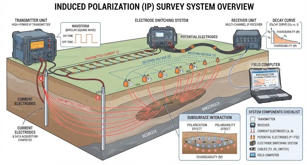
A transmitter should be evaluated as part of a complete geophysical acquisition system.
1. Main Components
A typical system may include:
- Transmitter.
- Receiver.
- Current electrodes.
- Potential electrodes.
- Multicore cables.
- Electrode switching system.
- Power supply.
- Positioning equipment.
- Acquisition and processing software.
2. Compatibility Requirements
Before purchasing, verify that the transmitter and receiver support compatible:
- Waveforms.
- Timing sequences.
- Current ranges.
- Synchronization methods.
- Communication interfaces.
- Acquisition software.
- Electrode switching architecture.
A mismatch may cause invalid measurements, operational delays, or the need for additional equipment.
3. System-Level Comparison
| Component | Main Function | Key Verification |
|---|---|---|
| Transmitter | Injects electrical energy | Output range and waveform |
| Receiver | Measures voltage and IP response | Sensitivity, range, synchronization |
| Electrodes | Establish electrical contact | Contact quality and compatibility |
| Cables | Connect the system | Insulation and electrical resistance |
| Switching system | Changes electrode combinations | Supported arrays and channel capacity |
| Power supply | Provides operating energy | Input requirements and duty cycle |
| Software | Controls acquisition and processing | Supported modes and data formats |
Ⅹ. How to Select the Right IP Transmitter
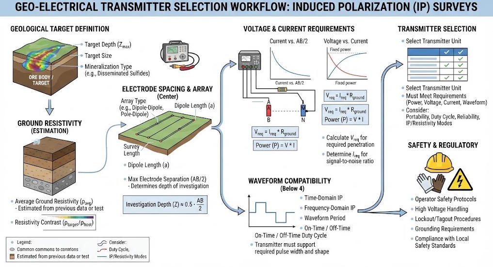
1. Define the Survey Objective
Identify the target type, expected depth, geological setting, and required resolution.
Determine whether the project requires resistivity, IP, or combined measurements.
2. Assess Ground Conditions
Consider expected resistivity, electrode contact, terrain, groundwater conditions, and cultural noise.
These factors influence electrical injection and measurement quality.
3. Determine Electrical Requirements
Estimate the required voltage, current, and power based on the survey geometry and expected circuit conditions.
Where appropriate, use preliminary field measurements to validate the assumptions.
Do not select equipment solely by its maximum power rating.
4. Verify IP Measurement Support
Confirm that the transmitter supports the required measurement method.
For TDIP, verify the waveform and timing requirements. For FDIP or SIP, verify the frequency range and signal-generation capabilities.
5. Check Receiver Compatibility
Confirm that the receiver can measure the expected voltage response and supports the transmitter’s operating sequence.
Verify synchronization and communication requirements before procurement.
6. Evaluate Field Logistics
Review equipment weight, power supply, installation time, transport, environmental limits, safety requirements, and service availability.
For remote projects, field maintenance and power logistics may significantly affect operational planning.
7. Compare the Complete System
Evaluate the transmitter, receiver, electrodes, cables, software, training, warranty, and technical support as a complete solution.
The best technical match depends on the project requirements, not on a single headline specification.
Ⅺ. Field Workflow and Quality Control

1. Survey Planning
Define the survey boundary, target, electrode array, spacing, measurement mode, and safety plan.
Review site access, underground utilities, cultural noise, and environmental conditions.
2. Equipment Inspection
Inspect the transmitter, receiver, cables, connectors, electrodes, and power supply.
Confirm that the system is configured according to the manufacturer’s documentation.
3. Electrode Installation
Install electrodes according to the survey design.
Check contact conditions and resolve poor connections using approved procedures.
4. Transmitter Setup
Configure the required output, waveform, timing, and operating limits.
Verify transmitter-receiver synchronization before collecting production data.
5. Data Acquisition
Monitor current, voltage, contact conditions, and noise.
Repeat or flag questionable readings according to the project’s quality-control plan.
6. Data Review
Check data completeness and measurement consistency.
Review outliers, repeatability, and acquisition settings before processing.
7. Interpretation
Process the data using methods appropriate to the survey type.
Interpret resistivity and IP models within the geological context and acknowledge uncertainty.
Ⅻ. Common Problems and Troubleshooting
| Symptom | Possible Cause | Recommended Check |
|---|---|---|
| Low injected current | High circuit resistance or output limit | Check electrodes, cables, and output settings |
| Unstable current | Changing contact or load | Inspect connections and electrode conditions |
| Noisy voltage readings | Cultural noise or poor contact | Review site conditions and electrode installation |
| Unexpected IP response | Timing mismatch or geological polarization effects | Verify waveform, timing, and receiver configuration |
| Intermittent transmission | Power supply or protection event | Check power source and fault indicators |
| Inconsistent readings | Setup changes or poor repeatability | Repeat measurements and document conditions |
These are possible diagnostic directions, not definitive fault diagnoses. Follow the manufacturer’s instructions before changing settings or servicing equipment.
ⅩⅢ. Electrical Safety and Field Operation
High-power IP and resistivity transmitters can generate hazardous electrical outputs.
1. Before Energizing
- Read the operating and safety documentation.
- Inspect cables, connectors, and electrode connections.
- Establish a controlled survey area.
- Keep unauthorized personnel away from energized equipment.
- Verify the protection and grounding arrangements specified by the manufacturer.
2. During Transmission
- Follow the approved operating procedure.
- Do not touch energized electrodes or exposed conductors.
- Do not connect or disconnect cables while transmitting.
- Stop transmission before inspecting a suspected fault.
- Treat cables and output terminals as potentially hazardous until the system is confirmed de-energized.
3. After Transmission
Stop the output and follow the manufacturer’s discharge and isolation procedure before handling the equipment.
Do not assume that a zero-current display alone confirms that the system is safe.
ⅩⅣ. High Power IP Transmitter Procurement Checklist
1. Technical Requirements
- Survey objective and measurement method.
- Required voltage and current range.
- Output power and operating mode.
- Waveform and timing.
- Receiver compatibility.
- Electrode configuration.
- Data acquisition and processing software.
2. Operational Requirements
- Available power supply.
- Field portability.
- Environmental operating limits.
- Safety documentation.
- Training and maintenance.
- Spare parts and technical support.
3. Documentation Requirements
Request and review:
- Technical specifications.
- Operating manual.
- Safety instructions.
- Calibration or verification documentation, where applicable.
- Compatibility information.
- Warranty and service terms.
4. Total System Evaluation
The transmitter should match the measurement objective and operate reliably within the complete acquisition system.
Compare the system’s capabilities, operating limitations, support, and lifecycle requirements rather than selecting by maximum power alone.
ⅩⅤ. Conclusion
A High Power IP Transmitter provides controlled electrical excitation for demanding induced polarization surveys. An Induced Polarization Transmitter supports polarization measurements, while a Resistivity Transmitter primarily supplies current for resistivity surveys. An IP Transmitter may support one or more IP measurement modes, depending on its design.
The correct selection depends on ground resistivity, electrode geometry, required current and voltage, waveform, timing, receiver compatibility, safety, and field conditions.
For professional geophysical exploration, evaluate the transmitter as part of a complete system that includes the receiver, electrodes, cables, acquisition software, and interpretation workflow. This approach supports reliable measurements and more defensible geological decisions.
Related Articles
| Title | Core Content | URL |
|---|---|---|
| High Power IP/ERT System | High-power IP and ERT system, transmitter configuration, and geophysical applications | https://geotechcn.net/products/electrical-instrument/high-power-ip-system/ |
| High Power IP System — 8-Channel Configuration | High-power IP system architecture, multichannel acquisition, and system specifications | https://geotechcn.net/products/electrical-instrument/high-power-ip-system-2/ |
| WDA-1 Super Digital DC Resistivity/IP Meter | Resistivity and IP measurement, integrated transmitter-receiver architecture, and electrical imaging | https://geotechcn.net/products/electrical-instrument/wda-1-dc-meter/ |
| WGMD-9 Distributed High-Density Electrical System | Multielectrode electrical survey system and resistivity/IP data acquisition | https://geotechcn.net/products/electrical-instrument/wgmd-9-distributed-system/ |
| What Are Resistivity Meters? | Resistivity measurement principles, equipment functions, and applications | https://geotechcn.net/service/what-are-resistivity-meters/ |
| Electrical Imaging, ERT & VES | Electrical imaging methods, electrode configurations, and subsurface investigation | https://geotechcn.net/service/electrical-imaging-ert-ves/ |
| Induced Polarization IP Method | IP principles, measurement methods, and exploration applications | https://geotechcn.net/service/induced-polarization-ip/ |
| Geophysical Surveying Explained | Geophysical survey methods and subsurface exploration technologies | https://geotechcn.net/service/geophysical-surveying-explained/ |
Reference Sources
| Title | Core Content | URL |
|---|---|---|
| U.S. EPA — Induced Polarization (IP) and Complex Resistivity | IP principles, time-domain and frequency-domain measurements, polarization mechanisms, and applications | https://www.epa.gov/environmental-geophysics/induced-polarization-ip-and-complex-resistivity |
| U.S. EPA — Electrical Resistivity | Electrical resistivity principles, field measurement approaches, and subsurface investigation | https://www.epa.gov/environmental-geophysics/electrical-resistivity |
| U.S. EPA — Electromagnetic Methods: Time-Domain | Time-domain electromagnetic principles and subsurface response interpretation | https://www.epa.gov/environmental-geophysics/electromagnetic-methods-time-domain |
| British Geological Survey — Geophysical Research | Geophysical investigation methods and geological applications | https://www.bgs.ac.uk/ |
| IEEE Standards Association | Electrical engineering standards and technical reference resources | https://standards.ieee.org/ |
FAQ
1. What is a High Power IP Transmitter?
A High Power IP Transmitter is a geophysical electrical source designed to inject controlled current for demanding induced polarization surveys. It supports electrical excitation for polarization measurements and may also support resistivity acquisition. Its suitability depends on ground resistance, electrode geometry, required current, voltage, waveform, receiver compatibility, and safe operating limits.
2. What is the difference between an Induced Polarization Transmitter and a Resistivity Transmitter?
An Induced Polarization Transmitter supports measurements of polarization-related electrical responses, while a Resistivity Transmitter primarily supplies controlled current for resistivity measurements. Some systems support both methods. The required waveform, timing, receiver compatibility, and survey objective determine whether an integrated transmitter is suitable.
3. How do I choose the right IP Transmitter for mineral exploration?
Start with the geological target, expected depth, ground resistivity, and electrode configuration. Then assess voltage, current, power, waveform, timing, receiver compatibility, and field safety. High-power capability may help under demanding electrical conditions, but actual performance depends on geology, survey design, noise, and measurement quality.
4. Does a High Power IP Transmitter always provide deeper exploration?
No. High electrical output does not guarantee greater investigation depth. Depth sensitivity depends on electrode geometry, geological conditions, target size, data quality, and interpretation methods. A suitable transmitter must provide sufficient output for the survey, but array design and geological context remain essential to reliable depth assessment.
5. Can one IP Transmitter perform both IP and resistivity surveys?
Yes, some IP Transmitters support both induced polarization and resistivity measurements. However, the system must provide the required waveform, current regulation, timing, and receiver compatibility. Before purchasing, verify the supported measurement modes, electrode configuration, software, and operating limitations for the intended survey.