Welcome to Geotech!
-1.png)


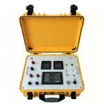
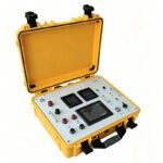
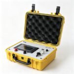
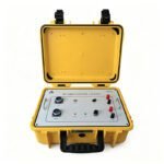
High Power IP/ERT System丨Induced Polarization (IP) Measurement System
PRODUCT PARAMETERS
Description
 Overview
 Overview
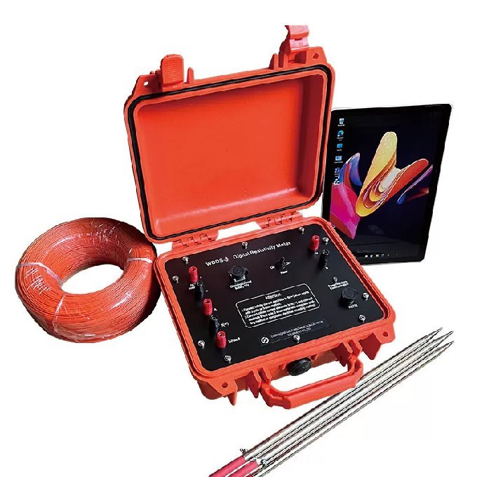
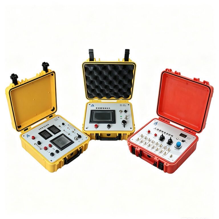
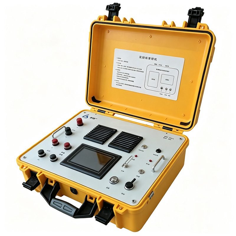
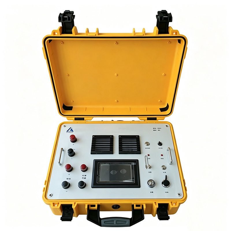
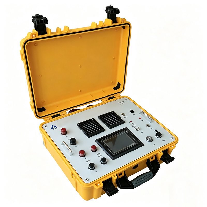
The high-power induced polarization (IP) measurement system integrates decades of expertise in geophysical exploration instrumentation with state-of-the-art electronic engineering.
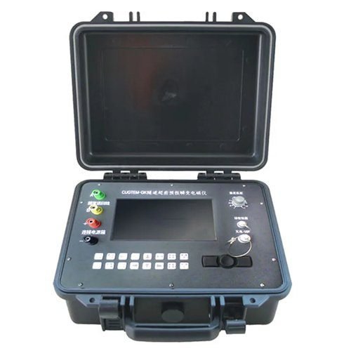
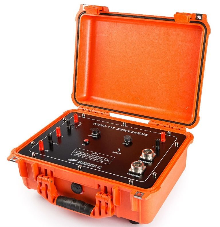
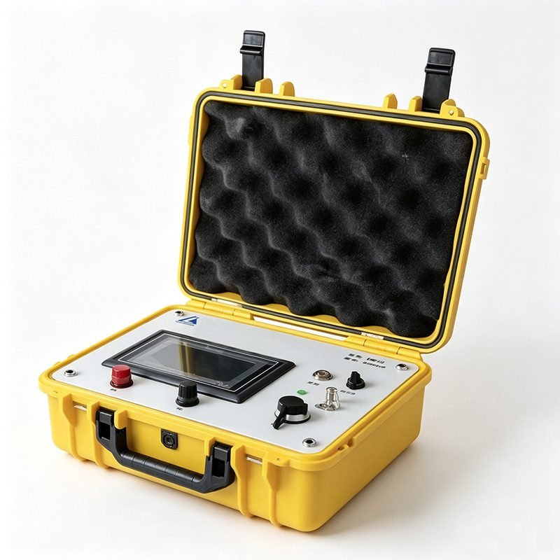
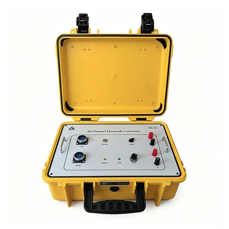
It features a 32-bit (A/D) conversion module, a real-time waveform visualization subsystem, and an embedded intelligent control platform—collectively enabling significant improvements in compactness, field portability, and key technical performance metrics. The system comprises three core components: a high-power direct-current (DC) IP transmitter, a high-precision multi-channel receiver, and a 60-channel electrode Converter unit.
Features
1. High-Power Transmission, Up to 3000V/10A
The transmitter delivers standard output of 1000V/5A. Maximum power reaches 5kW, expandable to 30kW with external power source. Maximum voltage reaches 3000V. Maximum current reaches 10A. This high-power output ensures sufficient signal penetration in high-resistivity formations. Deep ore bodies and groundwater aquifers at 500m depth are detectable. The system supports bipolar output with duty cycle 1:1. Power supply cycle ranges from 1s to 128s. Current measurement accuracy is ±1%.
2. 32-Bit ADC High-Precision Acquisition
The receiver adopts 32-bit A/D conversion module. Measuring voltage range is ±4.5V. Voltage resolution reaches 0.1μV. Voltage accuracy is ±0.1% ± 1 digit. Polarization accuracy is ±0.2%. Input impedance is 50MΩ. The system provides 4 secondary field time windows for IP decay analysis. Stack times are selectable from 1 to 10. Power-off delay is adjustable from 50ms to 500ms in ten steps. 50Hz power frequency suppression exceeds 80dB. Real-time waveform visualization enables on-site quality control.
3. 60-Channel Centralized Cable, Stable and Durable
The system includes a 60-channel electrode converter unit. Classic centralized cable architecture simplifies field deployment. Cables are designed for rugged field conditions. Damage resistance is significantly improved compared to distributed wireless systems. Large-scale 2D profiles and 3D grids are efficiently covered. Electrode arrays including Wenner, Schlumberger, dipole-dipole, and pole-dipole are fully supported.
4. Dual Synchronization Modes
The transmitter supports both software synchronization and GPS synchronization. Software sync suits short-distance wired setups. GPS sync enables long-offset configurations and time-domain IP surveys over large areas. Flexibility is ensured for diverse terrain and survey scales.
5. Real-Time Data Management
The transmitter features USB communication interface. Current storage time interval is adjustable from 1 to 30 minutes. Built-in data logging supports continuous monitoring. The receiver displays real-time data on a 4.3-inch 24-bit true color LCD. Field operators can verify data quality instantly. Invalid measurements are identified and repeated immediately.
6. AMT Integration for Deep Investigation
The system can combine with AMT (Audio Magnetotelluric) receiver for joint acquisition. Both IP/ERT and AMT data are collected in a single deployment. Combined interpretation achieves 500m investigation depth. This hybrid approach overcomes the depth limitation of pure DC methods. Deep crustal structures and concealed ore belts are effectively resolved.
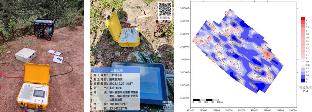
Technical Principles
The High Power IP/ERT System operates on the time-domain induced polarization (TDIP) method. The transmitter injects direct current into the ground through current electrodes A and B. The current is turned on for a specific duration (on-time), then turned off (off-time). The transmitted waveform repeats with opposite polarity. A complete cycle constitutes one measurement.
When current flows through the ground, metallic minerals and clay particles generate induced polarization effects. After current shut-off, a secondary voltage decay is observed. The receiver measures this decay across potential electrodes M and N. The chargeability (M) is calculated as the time integral of the secondary decay voltage normalized by the primary voltage.
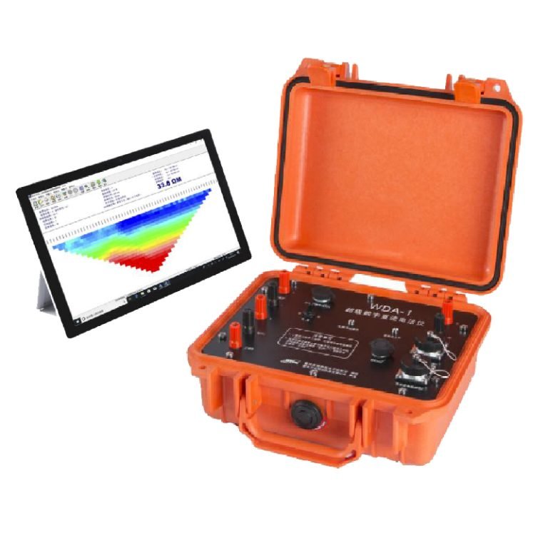
For electrical resistivity tomography (ERT), multiple electrode pairs are automatically switched. Apparent resistivity is calculated for each configuration. 2D or 3D resistivity models are obtained through iterative inversion algorithms.
| Comparison Dimension | Conventional IP System | High Power IP/ERT System |
|---|---|---|
| Output Voltage | ≤1000V | Up to 3000V |
| Output Current | ≤5A | Up to 10A |
| ADC Resolution | 16-24 bit | 32 bit |
| Channels | 1-10 | 60 channels |
| Max Power | 2-5kW | 5kW (30kW expandable) |
| Cable Type | Distributed wireless | Centralized robust cable |
| AMT Integration | Not supported | Supported |
| Investigation Depth | ~200m | Up to 500m |
Specifications
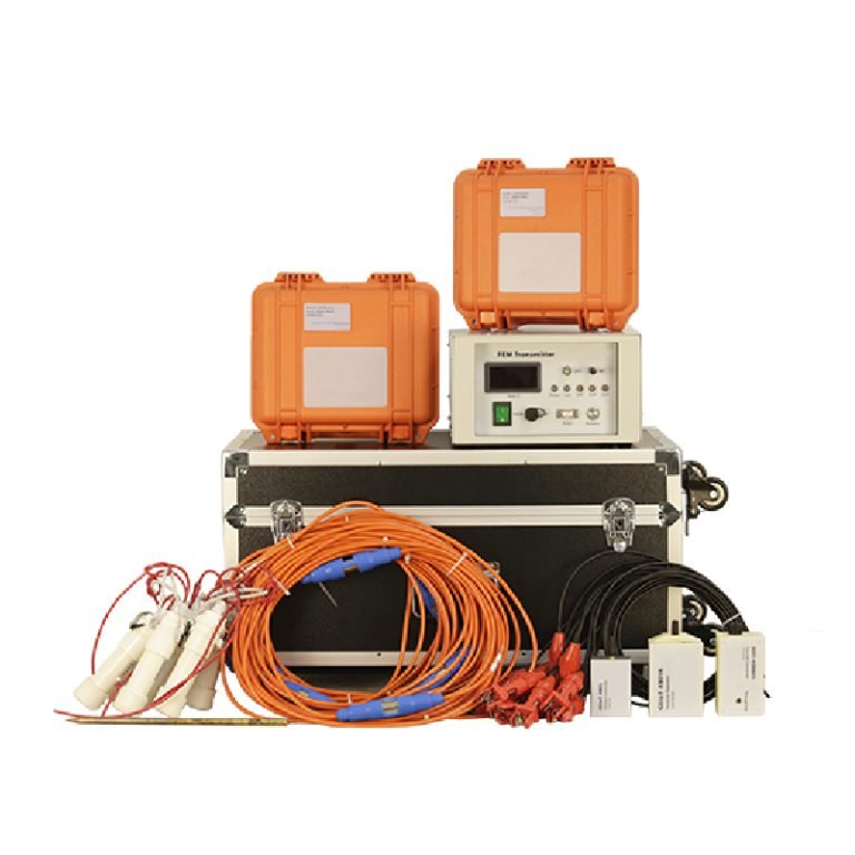
The High Power IP/ERT System comprises three core components. High-Power DC IP Transmitter. High-Precision Multi-Channel Receiver. 60-Channel Electrode Converter Unit.
1. High-Power DC IP Transmitter
| Parameter | Specification |
|---|---|
| Transmitting power | 5kW (max 30kW with external source) |
| Transmitting voltage | ±1000V (max 3000V) |
| Transmitting current | 5A (max 10A) |
| Current measurement accuracy | ±1% |
| Power supply cycle | 1s to 128s |
| Current storage interval | 1 to 30 minutes |
| Communication interface | USB |
| Synchronization mode | Software sync, GPS sync |
| Output band | Bipolar, duty cycle 1:1 |
| Display | 5-inch 24-bit true color LCD |
| Operating temperature | -10℃ to +50℃, humidity 95% |
| Storage temperature | -20℃ to 60℃ |
2. High-Precision Multi-Channel Receiver
| Parameter | Specification |
|---|---|
| Measuring voltage range | ±4.5V |
| Measuring voltage resolution | 0.1μV |
| Measuring voltage accuracy | ±0.1% ± 1 digit |
| Adaptable power supply time | 1s, 2s, 4s, 8s, 16s, 32s, 64s, 128s |
| Polarization accuracy | ±0.2% |
| Stack | 1 to 10 times selectable |
| Power-off delay | 50 to 500ms in ten steps |
| 50Hz power frequency suppression | >80dB |
| Input impedance | 50MΩ |
| Secondary field time window number | 4 |
| Synchronization mode | Software synchronization |
| Display | 4.3-inch 24-bit true color LCD |
3. 60-Channel Electrode Converter Unit
The converter unit manages automatic switching among 60 electrodes. Standard electrode spacing is customizable. Array configurations include Wenner, Schlumberger, dipole-dipole, and pole-dipole. The centralized cable design ensures signal integrity and operational stability. Cable damage risk is minimized through robust construction.
Applications
1. Mineral Exploration
Rapidly delineate disseminated sulfide ore bodies. Identify chargeable zones associated with copper, lead-zinc, and gold deposits. The high-power output penetrates conductive overburden. Deep-seated mineralization at 300-500m depth is detectable. 3D chargeability models guide drill targeting. Exploration risk is significantly reduced.
2. Groundwater Exploration
Map aquifer geometry and fracture zones. Distinguish freshwater from saline water through resistivity contrast. IP effects identify clay-rich aquitards. The 60-channel system covers large survey areas efficiently. Well placement is optimized based on geophysical models.
3. Geotechnical Engineering
Investigate subsurface conditions for foundation design. Detect cavities, faults, and weak zones. Monitor landslide slip surfaces. ERT provides high-resolution 2D/3D resistivity images. Engineering decisions are supported by quantitative geophysical data.
4. Environmental Site Assessment
Map contaminant plumes from landfills and industrial sites. Track groundwater pollution migration. Identify buried drums and underground storage tanks. Non-invasive surveys minimize environmental disturbance. Regulatory compliance is facilitated.
5. Deep Geothermal Exploration
When combined with AMT receiver, the system achieves 500m investigation depth. Geothermal reservoir boundaries are mapped. Fault and fracture networks controlling fluid flow are identified. Temperature anomalies are inferred from resistivity patterns.
Cases
Case 1: 3D Resistivity and Chargeability Survey
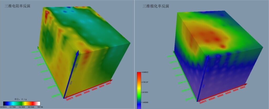
A large-scale 3D IP/ERT survey was conducted over a polymetallic mining district. The 60-channel system deployed 120 electrodes in a grid pattern. Wenner and dipole-dipole arrays were combined. High-power transmission at 2000V/8A ensured adequate signal in resistive host rocks. 3D resistivity and chargeability volumes were inverted. A concealed chargeable body at 350m depth was identified. Subsequent drilling intersected economic-grade copper mineralization.
Case 2: 2D Resistivity Profile for Groundwater
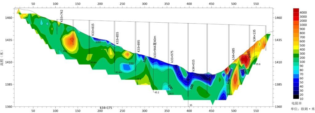
A 2D ERT profile was acquired across an alluvial basin for groundwater exploration. 60 electrodes at 10m spacing covered 590m profile length. Schlumberger and Wenner arrays provided complementary depth resolution. Resistivity sections clearly showed aquifer boundaries at 80-150m depth. Freshwater-saline water interface was mapped. Well drilling based on geophysical results achieved sustainable yield.
Case 3: IP + AMT Joint Acquisition for Deep Target
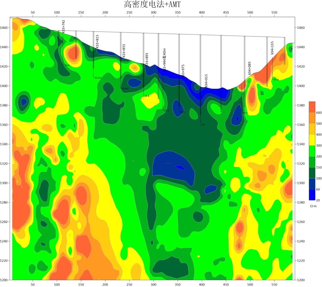
A deep exploration project required investigation below 500m. The High Power IP/ERT System was combined with AMT receiver. DC resistivity and IP data provided shallow-to-intermediate resolution. AMT data extended the depth range to 500m. Joint inversion produced a unified resistivity model. A deep conductive zone was interpreted as a buried graphite horizon. The integrated approach validated the exploration concept.
FAQ
In gravity exploration (SI), what is the unit of gravity? How to convert gravity units between SI and CGS?
① In SI, it is m·s-2, and one percent of it is the international unit abbreviation g.u.;
② Conversion between SI and CGS: 1g.u.=10-1 mGal
What are gravitational field and gravitational potential?
Gravitational field: The space around the earth with gravity is called the gravitational field.
Gravitational potential: The gravitational potential W in the gravitational field is equal to the work done by a particle of unit mass moving from infinity to that point.
What is the normal gravity field of the earth? What are the rules for the change of the normal gravity field with latitude and altitude?
① The normal gravity field of the earth: Assuming that the earth is a rotating ellipsoid (reference plane), the surface is glossy, the internal density is uniform, or it is distributed in concentric layers, the density of each layer is uniform, and the deviation of the shape of the ellipsoid from the geoid is very small, then the gravity field generated by the earth is the normal gravity field.
② The normal gravity value is only related to the latitude, the smallest at the equator and the largest at the poles, with a difference of about 50,000 g.u.; the rate of change of the normal gravity value with latitude is the largest at 45° latitude, and zero at the equator and the poles; the normal gravity value decreases with increasing altitude, and its rate of change is -3.086 g.u.. The main feature of the long-term change is the "westward drift" of the geomagnetic elements, both the dipole field and the non-dipole field drift westward, and have a global nature.
What is the relationship between gravitational field strength and gravitational acceleration?
The gravitational field strength is equal to the gravitational acceleration in both numerical and dimensional terms, and the two are in the same direction. In gravity exploration, all references to gravity refer to gravitational acceleration. The gravitational field strength at a point in space is equal to the gravitational acceleration at that point.
What is gravity exploration?
Gravity exploration is an exploration method that is based on the density difference of rocks and ores. Since density difference will cause local changes in the normal gravity field of the earth (i.e. gravity anomaly), it is used to solve geological problems by observing and studying gravity anomalies.