Welcome to Geotech!


Electrode Arrays in Geophysics: Principles, Types, and Selection for ERT
Overview:Electrode arrays define how current enters the ground and how electrical potential differences are measured. Understanding Electrode Arrays helps survey teams design reliable Electrical Resistivity Tomography (ERT) investigations. This guide explains common configurations, geometric factors, depth sensitivity, and field limitations. It also compares Electrode Arrays for groundwater, engineering, and environmental studies, helping professionals select Electrical Resistivity Tomography (ERT) methods that match geological conditions and project objectives.
Ⅰ. What Are Electrode Arrays?
1. Definition of Electrode Arrays
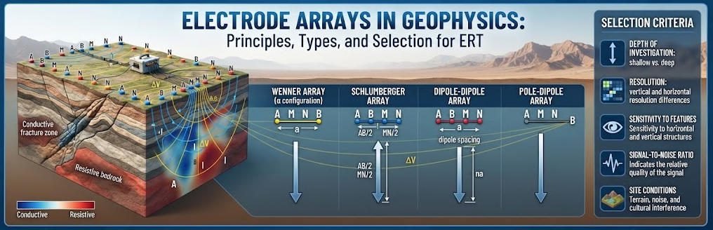
An electrode array is a defined arrangement of electrodes used to inject electrical current into the ground and measure the resulting potential difference. In resistivity surveys, the arrangement determines the geometric factor used to calculate apparent resistivity.
A conventional four-electrode measurement uses two current electrodes and two potential electrodes. The current electrodes inject and withdraw current. The potential electrodes measure the voltage difference produced by the subsurface electrical field. The US Environmental Protection Agency describes this four-electrode principle as the basis of electrical resistivity methods.
2. The Four Electrodes in a Resistivity Survey
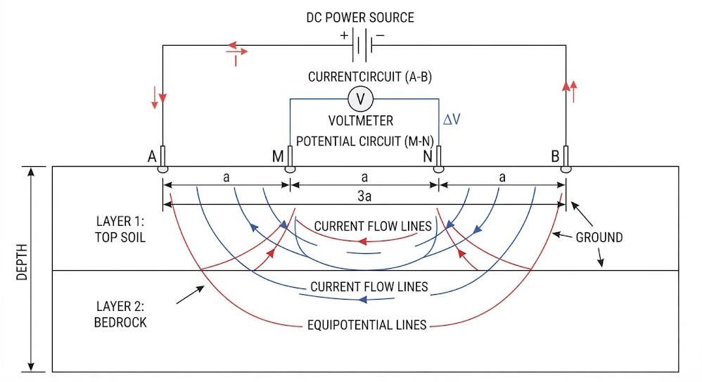
A typical four-electrode configuration contains:
- A and B: Current electrodes that inject and return electrical current.
- M and N: Potential electrodes that measure voltage difference.
- I: Injected current, measured in amperes.
- ΔV: Measured potential difference, measured in volts.
The instrument measures resistance:
R=IΔV
The resistance depends on the electrode arrangement and the electrical properties of the ground.
The survey then applies a geometric factor to calculate apparent resistivity.
3. Electrode Arrays and ERT
ERT uses many electrodes distributed along a profile or across a survey area. An automated switching system selects different electrode combinations for successive measurements.
The resulting dataset contains apparent resistivity measurements from multiple current and potential configurations. Inversion software uses these measurements to estimate a spatial distribution of subsurface resistivity.
ERT does not directly photograph underground structures. It produces a model of electrical properties constrained by measurement geometry, data quality, and inversion assumptions.
Ⅱ. Physical Principles and Apparent Resistivity
1. How Electrical Current Travels Through the Ground
When current enters the ground through an electrode, it creates an electrical potential field. The distribution depends on subsurface resistivity, geological structure, and electrode geometry.
In a homogeneous, isotropic half-space, the potential from a point current source decreases with distance from the electrode. In layered or heterogeneous ground, current distribution becomes more complex.
Conductive materials may include saline groundwater, clay-rich formations, and some mineralized zones. Resistive materials may include dry, competent rock and some coarse, unsaturated deposits. These are general tendencies, not unique material signatures.
2. The Apparent Resistivity Equation
The general relationship is:
ρa=KIΔV=KR
Where:
- ρa = apparent resistivity, in ohm-metres (Ω·m).
- K = geometric factor, in metres.
- ΔV = measured voltage difference, in volts.
- I = injected current, in amperes.
- R = measured resistance, in ohms.
The geometric factor depends on the positions of the current and potential electrodes.
Apparent resistivity is not necessarily the true resistivity of a specific underground layer. It is the equivalent resistivity that a homogeneous half-space would have under the same electrode geometry and measured resistance.
3. Geometric Factor for a General Four-Electrode Array
For point electrodes on a flat surface over a homogeneous half-space, a common expression is:
K=(AM1−BM1)−(AN1−BN1)2π
Here, AM, BM, AN, and BN represent electrode separations. The sign depends on the voltage and current conventions.
For practical processing, the instrument or software must use the correct electrode coordinates and measurement polarity. Incorrect geometry can produce systematic resistivity errors.
4. Why Electrode Geometry Matters
Different arrays sample different portions of the subsurface electrical field. Their sensitivity patterns determine which structures they can resolve effectively.
Three factors are particularly important:
- Signal strength: The measured voltage must exceed instrument noise and environmental interference.
- Sensitivity distribution: The array must be sensitive to the target’s location, size, orientation, and resistivity contrast.
- Measurement coverage: The survey must include enough independent measurements to constrain the desired model.
Array selection is therefore a survey-design decision, not merely a cable-layout preference.
Ⅲ. Common Electrode Array Types
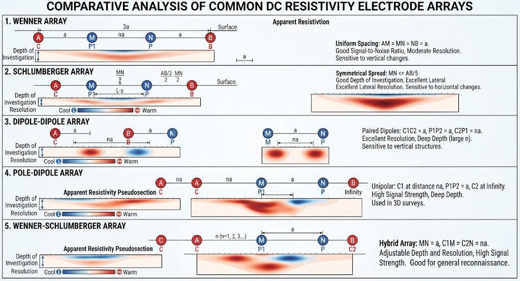
1. Wenner Array
The Wenner array uses four collinear electrodes with equal adjacent spacing a.
The arrangement is:
A — M — N — B
Each adjacent electrode pair is separated by a. A and B inject current, while M and N measure voltage.
For the ideal homogeneous half-space:
K=2πa
Therefore:
ρa=2πaIΔV
The Wenner array often produces relatively strong voltage signals for a given survey geometry. It is useful for shallow investigations and surveys that require robust measurements.
Typical applications:
- Near-surface engineering investigations.
- Soil and weathered-layer characterization.
- Environmental surveys.
- Groundwater investigations where the target geometry suits the array.
Limitations: The Wenner array may provide less lateral detail than some dipole-based configurations for certain targets. Its performance depends on electrode spacing, target geometry, and ground conditions.
2. Schlumberger Array
The Schlumberger array places the potential electrodes near the center and the current electrodes farther apart.
The current electrodes move outward as the survey expands. The potential-electrode spacing usually remains relatively small until the measured voltage becomes too weak.
For a symmetric configuration, let AB represent the full current-electrode separation and MN the full potential-electrode separation.
The geometric factor is:
K=π4MNAB2−MN2
This formula applies to the conventional symmetric four-electrode arrangement.
Typical applications:
- Vertical electrical sounding (VES).
- Layered subsurface investigations.
- Overburden and bedrock assessment.
- Preliminary groundwater exploration.
Limitations: The classical Schlumberger arrangement is particularly suited to sounding. Strong lateral heterogeneity can complicate interpretation because the underlying one-dimensional assumption may not hold.
3. Dipole-Dipole Array
The dipole-dipole array uses a current dipole and a potential dipole.
The current electrodes form one pair. The potential electrodes form another pair. The distance between the dipoles increases according to a separation factor, commonly denoted by n.
For equal dipole lengths a and a standard collinear arrangement:
K=πan(n+1)(n+2)
This expression assumes the conventional dipole-dipole geometry and standard separation-factor definition.
The array is sensitive to lateral resistivity variations and can help delineate steep boundaries, faults, and localized anomalies.
Typical applications:
- Geological structure mapping.
- Mineral exploration.
- Fracture and fault investigations.
- Environmental surveys involving lateral contrasts.
Limitations: Signal strength can decline as dipole separation increases. Large separation factors may produce weak voltage measurements and greater sensitivity to noise.
4. Pole-Dipole Array
The pole-dipole array uses one current electrode within the survey area and a second current electrode placed sufficiently far away to approximate a remote pole.
A potential dipole measures the voltage difference at two nearby locations.
The remote electrode must be positioned with care. If it is too close, its influence can distort the intended geometry.
Typical applications:
- Two-dimensional resistivity imaging.
- Surveys where asymmetric electrode geometry is practical.
- Investigations that require flexible profile coverage.
Limitations: The array can exhibit directional sensitivity. Forward and reverse measurements may help evaluate asymmetry and improve interpretation.
5. Pole-Pole Array
The pole-pole array uses a current electrode and a potential electrode within the survey area, with their corresponding return or reference electrodes placed remotely.
Its geometry can provide broad depth sensitivity in some configurations.
However, remote electrodes require suitable locations and adequate separation. Their influence must be considered in the geometric factor and data interpretation.
Typical applications:
- Specialized resistivity investigations.
- Surveys where remote electrode placement is feasible.
Limitations: Remote electrode logistics and environmental noise can complicate field deployment. The nominally remote electrodes do not become mathematically irrelevant unless the approximation is justified.
6. Wenner-Schlumberger Array
The Wenner-Schlumberger array combines characteristics of Wenner and Schlumberger geometries.
It uses a symmetric four-electrode arrangement. The current-electrode separation is larger than the potential-electrode separation.
The array provides a practical balance between sensitivity to vertical and lateral resistivity variations. It is widely used in two-dimensional ERT surveys.
Typical applications:
- Engineering site characterization.
- Groundwater and bedrock investigations.
- Environmental surveys.
- General-purpose ERT profiling.
Limitations: The array may not provide the same sensitivity to every target as a specialized configuration. Its suitability should be tested against the expected geological model.
7. Gradient and Multiple-Gradient Arrays
Gradient arrays use a current-electrode pair with multiple potential-electrode pairs distributed within the region between or around the current electrodes.
Multiple-gradient acquisition can collect many measurements efficiently. It is useful for surveys that require broad coverage and high acquisition productivity.
Typical applications:
- Large two-dimensional ERT profiles.
- Surveys with multi-channel acquisition systems.
- Projects requiring dense measurement coverage.
Limitations: Measurement density alone does not guarantee improved resolution. Array geometry, data errors, electrode contact, and inversion settings remain critical.
Ⅳ. Electrode Array Comparison and Selection
1. Comparison of Common Arrays
| Array | Main Sensitivity | Typical Strength | Main Limitation |
|---|---|---|---|
| Wenner | Layered and near-surface variations | Often strong signals | May provide less detail for some lateral targets |
| Schlumberger | Vertical layering in sounding | Efficient expansion of current spacing | Sensitive to departures from 1D assumptions |
| Dipole-Dipole | Lateral resistivity changes | Useful for steep boundaries and localized anomalies | Weak signals at large separation factors |
| Pole-Dipole | Mixed sensitivity | Flexible profile geometry | Remote electrode and directional effects |
| Pole-Pole | Broad sensitivity in suitable geometry | Flexible spacing and potential depth coverage | Remote-electrode requirements |
| Wenner-Schlumberger | Mixed vertical and lateral sensitivity | Balanced response | Not optimal for every target |
| Gradient | Broad spatial coverage | Efficient multi-channel acquisition | Requires careful design and quality control |
Array performance depends on the geological model, measurement geometry, noise conditions, and inversion approach. Published numerical comparisons also show that no configuration is universally optimal.
2. Selection by Investigation Objective
| Investigation Objective | Candidate Array | Key Design Consideration |
|---|---|---|
| Layered soil and weathered zone | Wenner or Schlumberger | Vertical layering and target depth |
| Bedrock depth estimation | Schlumberger or Wenner-Schlumberger | Line length and expected layer geometry |
| Steep fault or fracture zone | Dipole-Dipole or Pole-Dipole | Lateral sensitivity and signal-to-noise ratio |
| General engineering ERT | Wenner-Schlumberger or combined arrays | Balance of coverage and resolution |
| Localized resistivity anomaly | Dipole-Dipole or gradient-based design | Target size and measurement density |
| Large-area ERT mapping | Gradient or multi-array acquisition | Coverage, channel count, and field logistics |
| Complex three-dimensional geology | 3D multi-array design | Electrode layout in both horizontal directions |
These are starting points rather than universal prescriptions. The final choice should reflect the target geometry and local geological conditions.
3. Choosing Between a Single Array and Hybrid Acquisition
A single array can simplify survey planning and data interpretation. It may be sufficient when the target is well understood and the geometry matches the survey objective.
Hybrid acquisition combines two or more array configurations. It can improve spatial coverage and reduce reliance on one sensitivity pattern.
However, combining arrays does not automatically increase model accuracy. Additional measurements must contribute useful independent sensitivity and maintain acceptable data quality.
4. Decision Factors for Array Selection
Before selecting an array, evaluate:
- Target depth: How deep must the survey investigate?
- Target geometry: Is the target horizontal, steeply dipping, irregular, or isolated?
- Resistivity contrast: How different is the target from the surrounding ground?
- Geological complexity: Are lateral and vertical changes both expected?
- Noise environment: Are power lines, buried utilities, or industrial equipment present?
- Site access: Can the crew install electrodes along the intended profile?
- Equipment capability: Does the instrument support the required array and electrode count?
- Interpretation resources: Can the project support appropriate 2D or 3D inversion and validation?
Ⅴ. Electrode Spacing, Survey Depth, and Resolution
1. How Electrode Spacing Affects Investigation Depth
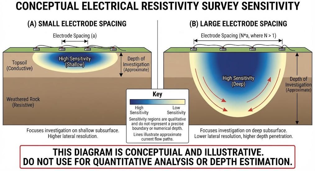
Electrode spacing influences the spatial scale of the electrical field. Larger separations generally increase sensitivity to deeper regions, while smaller separations provide denser sampling of shallow structures.
However, electrode spacing is not a direct depth measurement.
The depth of investigation depends on array geometry, profile length, subsurface resistivity, noise, and the sensitivity distribution of the measurements.
EPA guidance provides approximate depth relationships for certain idealized arrays, but emphasizes that site-specific depth-of-investigation assessment can be more appropriate.
2. Electrode Spacing and Spatial Resolution
Smaller electrode spacing can improve the ability to sample shallow variations. It does not guarantee that every small target will be resolved.
Resolution also depends on:
- Target size and resistivity contrast.
- Measurement density and array sensitivity.
- Electrode contact quality.
- Instrument noise and measurement repeatability.
- Inversion regularization and model parameterization.
A survey designed for a deep target may require a longer profile and larger electrode spacing. A shallow engineering survey may prioritize tighter spacing and denser measurements.
3. Profile Length and Survey Design
Profile length controls the horizontal coverage and influences the range of electrode separations available.
The survey line should extend beyond the target area when site conditions allow. This helps reduce edge effects and provides additional sensitivity around the target.
The required extension depends on the array, target dimensions, expected depth, and inversion model.
4. Depth of Investigation Versus Model Depth
A resistivity inversion may display a model extending to substantial depth. That does not mean the survey reliably resolves every feature at that depth.
The depth of investigation (DOI) describes the depth below which the data provide insufficient sensitivity to constrain the model reliably.
A responsible interpretation should distinguish between:
- The displayed model depth.
- The depth range supported by measurement sensitivity.
- The depth range with adequate resolution for the target.
DOI assessment may involve sensitivity analysis, alternative-model comparisons, and examination of inversion stability.
Ⅵ. Field Deployment and Data Acquisition Workflow
1. Define the Survey Objective
Start with a geological question rather than an equipment specification.
Examples include locating a weathered bedrock surface, mapping a conductive groundwater-bearing zone, or identifying a resistivity contrast associated with a suspected fault.
Define the target depth, expected geometry, required coverage, and available ground-truth information.
2. Conduct a Site Reconnaissance
Review geological maps, borehole records, topography, site access, and potential sources of electrical interference.
Identify buried utilities, fences, pipelines, and other conductive structures. These features may affect current flow or create misleading anomalies.
Where appropriate, consult existing geotechnical or hydrogeological data before finalizing the survey design.
3. Design the Electrode Layout
Choose the array geometry and electrode spacing based on the target and site conditions.
Determine:
- Number of electrodes.
- Profile length and orientation.
- Electrode spacing.
- Array sequence.
- Required remote-electrode locations, if applicable.
- Expected data volume and acquisition time.
For complex targets, evaluate more than one array through forward modeling or synthetic-data tests.
4. Install Electrodes and Verify Contact
Place electrodes at the planned locations. Ensure that each electrode has stable electrical contact with the ground.
Dry, coarse, or rocky surfaces may create high contact resistance. Moisture, electrode insertion depth, and contact materials may affect the measured response.
Use instrument-supported contact checks and follow the equipment manufacturer’s procedures. Avoid introducing conductive materials that could contaminate the site or compromise the measurement.
5. Configure the Instrument
Set the survey geometry, electrode numbering, current limits, measurement sequence, and acquisition parameters.
Confirm that the instrument’s electrode map matches the actual field layout.
For multi-electrode systems, verify the switching unit, cables, connectors, power supply, and communication links before starting the full survey.
6. Acquire and Monitor Data
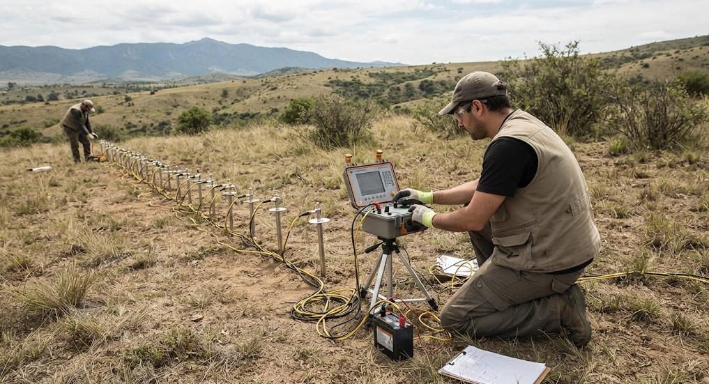
Monitor voltage measurements, injected current, contact resistance, repeated readings, and rejected measurements.
Review data quality during acquisition rather than waiting until the end of the survey.
If readings become unstable, investigate electrode contact, cable connections, environmental interference, and instrument settings.
7. Perform Quality Control and Inversion
Before inversion, review:
- Missing and rejected measurements.
- Repeated-measurement consistency.
- Electrode-coordinate accuracy.
- Geometric-factor and polarity conventions.
- Outliers and possible cultural interference.
- Data error estimates.
Select an inversion approach suited to the geology and survey geometry. Evaluate residuals, model sensitivity, and stability rather than relying on a visually smooth section alone.
8. Interpret and Validate Results
Interpret resistivity patterns using geological knowledge and independent information.
Where possible, compare the model with borehole logs, geological mapping, groundwater observations, or other geophysical methods.
Report uncertainty and limitations. Resistivity anomalies can have multiple geological explanations, so interpretations should remain consistent with the available evidence.
Ⅶ. Data Quality, Noise, and Common Field Problems
1. High Contact Resistance
Poor electrode contact can reduce injected current or destabilize voltage measurements.
Potential causes include dry soil, coarse gravel, weathered rock, loose connections, and inadequate electrode insertion.
Recommended response: Inspect the electrode, improve contact using an approved method, verify the cable connection, and repeat the measurement.
2. Weak Voltage Signals
Some configurations produce weak voltage responses, particularly at larger electrode separations or in unfavorable geological conditions.
Low voltage can increase the influence of electrical noise and measurement uncertainty.
Recommended response: Review the array geometry, injection current within safe instrument limits, stacking settings, electrode contact, and environmental interference.
3. Cultural and Electrical Interference
Power lines, buried metallic infrastructure, electric fences, and industrial equipment can affect measurements.
The impact depends on the source, frequency, location, and survey geometry.
Recommended response: Document interference sources, evaluate repeatability, and consider alternative measurement sequences or survey timing where feasible.
4. Incorrect Electrode Coordinates
Incorrect electrode positions can produce geometric-factor errors and distort inversion results.
This issue is particularly important when crews use irregular spacing, topographic corrections, or three-dimensional layouts.
Recommended response: Verify electrode numbering and coordinates before acquisition. Record deviations from the planned layout.
5. Overinterpreting Resistivity Anomalies
A low-resistivity anomaly does not automatically indicate groundwater or contamination. Clay content, salinity, saturation, and other factors can produce similar responses.
Likewise, a high-resistivity anomaly does not uniquely identify competent bedrock.
Recommended response: Interpret resistivity together with geological context and independent observations.
Ⅷ. Electrode Arrays in Practical Applications
1. Groundwater Exploration
ERT can help identify resistivity contrasts associated with weathered zones, fractures, saturated formations, and changes in lithology.
A Wenner-Schlumberger or combined-array survey may be appropriate for general groundwater investigations. Dipole-dipole measurements may contribute additional sensitivity to lateral structures.
However, resistivity alone cannot confirm groundwater yield or water quality. Boreholes, pumping tests, and hydrogeological evidence may be required.
2. Engineering Geology and Infrastructure
Electrode arrays can help investigate bedrock depth, weathered zones, possible voids, and geological discontinuities.
Wenner-Schlumberger configurations are often considered for general engineering profiles. Dipole-dipole configurations may help resolve steep lateral boundaries.
The survey design should account for site access, utilities, terrain, and the scale of the engineering target.
3. Environmental Investigations
ERT can map electrical contrasts associated with leachate, saline groundwater, and changes in soil or groundwater conditions.
A low-resistivity zone may indicate increased conductivity, but it does not identify a contaminant or concentration by itself.
Environmental interpretations should incorporate hydrogeological data, sampling results, and relevant site history.
4. Mineral Exploration
Resistivity arrays can support the mapping of conductive or resistive geological structures. Dipole-dipole and other suitable configurations may help investigate lateral anomalies.
For disseminated sulfide exploration, induced polarization (IP) measurements may add information about chargeability.
Resistivity and IP responses are not unique mineral indicators. Geological mapping, geochemical data, and other geophysical methods may be needed to evaluate targets.
5. Three-Dimensional ERT Surveys
Three-dimensional ERT uses electrodes distributed across an area rather than along a single profile.
This geometry can help characterize targets with significant lateral variation in more than one direction.
However, 3D surveys require careful electrode positioning, adequate data coverage, suitable inversion software, and greater field coordination. Their value depends on whether the target geometry justifies the added complexity.
Ⅸ. How to Choose an ERT System for Electrode Arrays
1. Check Array Compatibility
Confirm that the instrument supports the array configurations required by the project.
Review whether it supports Wenner, Schlumberger, dipole-dipole, pole-dipole, gradient, and hybrid sequences as needed.
Do not assume that every multi-electrode instrument supports every array or acquisition mode.
2. Evaluate Electrode Count and Switching
The electrode count affects profile coverage and the number of available measurement combinations.
An automated switching system can reduce manual electrode movement. Its practical efficiency depends on the measurement sequence, field conditions, and system design.
3. Review Current Injection and Measurement Performance
Evaluate current output, voltage measurement range, noise performance, stacking options, and protection features.
Required performance depends on ground resistivity, electrode contact, target depth, and array geometry.
Higher power alone does not guarantee better data. Measurement stability and suitable survey design remain essential.
4. Check Software and Data Compatibility
Review whether the system supports the required inversion workflow and data-export formats.
Confirm that the software handles electrode coordinates, topography, array geometry, quality-control flags, and appropriate model constraints.
For complex surveys, check whether the workflow supports 2D or 3D inversion as required.
5. Compare Field Support and Total Project Cost
Consider equipment purchase cost alongside cables, electrodes, switching units, software, training, maintenance, and technical support.
For international projects, also review spare-part availability, documentation, communication support, and warranty terms.
A suitable system should match the actual survey objectives rather than maximize specifications that the project does not need.
Ⅹ. Conclusions
Electrode arrays determine how electrical resistivity surveys sample the subsurface. Their geometry influences apparent resistivity, sensitivity, signal strength, and the reliability of the resulting model.
Wenner, Schlumberger, dipole-dipole, pole-dipole, pole-pole, Wenner-Schlumberger, and gradient arrays each serve different survey needs. The correct choice depends on target geometry, geology, depth, noise, and field constraints.
Reliable ERT results require more than a suitable array. Accurate electrode positioning, stable contact, quality-controlled acquisition, appropriate inversion, and geological validation are equally important.
For professional surveys, array selection should begin with the geological question and end with a defensible interpretation of what the data can—and cannot—resolve.
Related Articles
| Title | Core Content | URL |
|---|---|---|
| Resistivity Survey Methods and ERT Guide | Resistivity survey methods, array configurations, and field selection | https://geotechcn.net/service/resistivity-surveying-techniques/ |
| What Is Electrical Resistivity Tomography (ERT)? | ERT principles, electrode arrangements, and subsurface imaging | https://geotechcn.net/service/what-is-electrical-resistivity-tomography/ |
| ERT Geophysics: Principles, Arrays & Field Applications | ERT principles, array sensitivity, and practical applications | https://geotechcn.net/service/ert-geophysics-principles/ |
| What is Vertical Electrical Sounding (VES)? | Schlumberger and Wenner configurations for vertical sounding | https://geotechcn.net/service/what-is-vertical-electrical-sounding-ves/ |
| High-Density Resistivity: ERT System & Applications | High-density resistivity acquisition and electrode configurations | https://geotechcn.net/service/high-density-resistivity-20250301/ |
| Geophysical Methods: Electrical Resistivity Tomography (ERT) | Electrode geometry, apparent resistivity, and ERT survey methods | https://geotechcn.com/service/geophysical-methods-ert-guide/ |
Reference Sources
| Title | Core Content | URL |
|---|---|---|
| Electrical Resistivity — US EPA | Electrical resistivity principles, apparent resistivity, electrode arrays, and depth of investigation | https://www.epa.gov/environmental-geophysics/electrical-resistivity |
| A Numerical Comparison of 2D Resistivity Imaging with 10 Electrode Arrays | Numerical comparison of electrode-array resolution and imaging performance | https://onlinelibrary.wiley.com/doi/10.1111/j.1365-2478.2004.00423.x |
| Comparative Tests on Different Multi-Electrode Arrays Using Models in Near-Surface Geophysics | Array comparison using synthetic models and field surveys | https://academic.oup.com/jge/article/6/1/1/5127399 |
| Induced Polarization (IP) and Complex Resistivity — US EPA | IP acquisition, electrode configurations, and signal-quality considerations | https://www.epa.gov/environmental-geophysics/induced-polarization-ip-and-complex-resistivity |
| Investigating the Performance of Electrical Resistivity Arrays | Technical study of common DC resistivity arrays and their performance | https://vtechworks.lib.vt.edu/server/api/core/bitstreams/86b27899-05e2-4882-b31b-22e8b468d8d6/content |
FAQ
Q1. What is an electrode array in geophysics?
An electrode array is a defined arrangement of electrodes used to inject electrical current and measure voltage differences in the ground. Its geometry determines the geometric factor and influences subsurface sensitivity. Engineers use different arrays to investigate geological layering, faults, groundwater-bearing formations, and environmental anomalies through resistivity surveys.
Q2. What is the difference between Wenner and dipole-dipole arrays?
The Wenner array uses four equally spaced electrodes and often provides strong voltage signals. The dipole-dipole array separates current and potential dipoles, making it useful for investigating lateral resistivity changes. Engineers select between them according to target geometry, noise conditions, and required resolution.
Q3. Which electrode array is best for groundwater exploration?
No electrode array is universally best for groundwater exploration. Wenner-Schlumberger and Schlumberger configurations can support investigations of layered formations, while dipole-dipole measurements may help identify lateral structures. The final design depends on geology, target depth, groundwater conditions, and independent hydrogeological evidence.
Q4.How does electrode spacing affect investigation depth?
Larger electrode separations generally increase sensitivity to deeper regions, while smaller spacing supports denser sampling of shallow structures. However, spacing does not determine depth by itself. Array geometry, profile length, subsurface resistivity, noise, and inversion sensitivity all influence the effective depth of investigation.
Q5. Can different electrode arrays be combined in one ERT survey?
Yes. Hybrid acquisition combines multiple array configurations to improve measurement coverage and sample different sensitivity patterns. It can be useful in complex geological settings. However, combining arrays does not guarantee better results. Engineers must evaluate data quality, survey geometry, acquisition efficiency, and inversion stability.