Welcome to Geotech!
-1.png)


Principles and Simulation Experiments of Potential Measurement Method
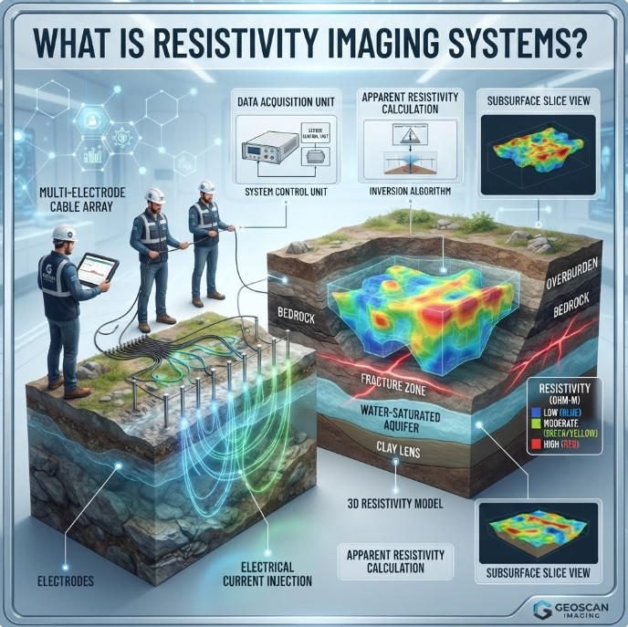
TIPS:Electrical resistivity method and induced polarization method form the foundation of geophysical electrical exploration. This guide explains how electrical resistivity method detects subsurface structures through current injection. You will learn induced polarization method principles for mineral discrimination. We compare electrode arrays and applications for electrical resistivity method and induced polarization method professionals.
Introduction
This article analyzes the application of high-density electrical method in underground resistivity detection, focusing on comparing the technical characteristics of Centralized and Distributed high-density electrical measurement systems. Field experimental data from Geotech’s equipment verifies the consistency between potential measurement principles and electromagnetic induction laws.
01 Principles of Potential Measurement Method
Electric Field Distribution Characteristics
When using the centralized high-density electrical method, the ground electrode can be regarded as a point current source. According to Coulomb’s law:
E=kr2q
The electric field strength is inversely proportional to the square of the distance and approaches infinity at the point charge. The distributed high-density electrical method can effectively improve this phenomenon by arranging multiple electrodes.
When using Centralized high-density electrical method, grounding electrodes can be regarded as point current sources. According to Coulomb’s law:
E=kr2q
The electric field intensity is inversely proportional to the square of the distance, approaching infinity at the point charge. Distributed high-density electrical method effectively improves this phenomenon through multi-electrode arrangement.
02 Engineering Layout and Data Acquisition
System Architecture Comparison
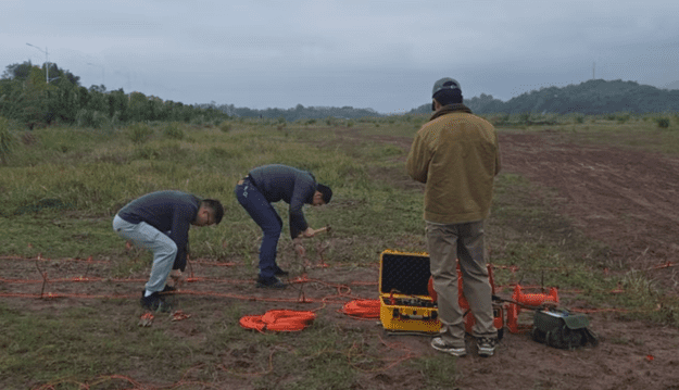
The experiment uses Geotech’s Centralized HDEM system:
- Maximum 50-channel expansion
- 4G remote monitoring
- Automatic polarization compensation
Compared with Distributed HDEM:
- Modular deployment
- Local intelligent processing
- Networked collaboration
03 Data Analysis and Verification
Potential-Voltage Linearity

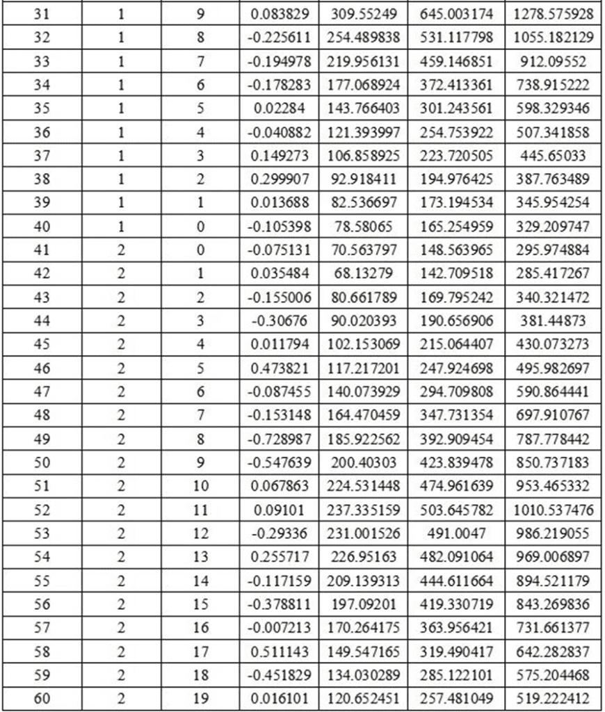
Table 2.3 shows that when the supply voltage increases from 100V to 300V, the potential values at each measurement point maintain strict proportional relationship (R²>0.99), verifying the stability of Centralized HDEM measurements.
04 Engineering Application Fields
HDEM technology has been successfully applied in:
- Hydraulic engineering leakage detection (Centralized solution)
- Landfill monitoring (Distributed deployment)
- Cultural relic crack water detection (Hybrid layout)
Reference Sources
| Organization Name | Organization Type | Website | Citation Application Scenario |
|---|---|---|---|
| Society of Exploration Geophysicists (SEG) | International Professional Society | https://seg.org/ | DC resistivity and IP method standards |
| U.S. Geological Survey (USGS) | Government Geological Survey Agency | https://www.usgs.gov/ | Groundwater exploration and environmental geophysics |
| Geological Survey of India (GSI) | Government Geological Survey Agency | https://www.gsi.gov.in/ | Electrical methods training and best practices |
| European Association of Geoscientists & Engineers (EAGE) | European Geoscience Society | https://eage.org/ | Near-surface geophysics and engineering applications |
| International Association of Hydrogeologists (IAH) | International Hydrogeology Association | https://iah.org/ | Groundwater geophysics and aquifer characterization |
FAQ
What is the difference between resistivity and induced polarization methods?
Resistivity measures how easily current flows through subsurface materials. IP measures the delayed voltage response after current shutoff, indicating charge storage capacity. Resistivity maps geological structures. IP identifies metallic minerals and clay content. The WDA-1 meter performs both methods in one survey.
Which electrode array is best for groundwater exploration?
The Wenner array is best for groundwater exploration. It provides high signal-to-noise ratio and excellent vertical resolution. It clearly resolves horizontal aquifer boundaries. Schlumberger arrays work well for deep bedrock aquifers. Dipole-dipole arrays suit fault-controlled groundwater systems.
How deep can DC resistivity methods detect?
Detection depth depends on electrode spacing and ground resistivity. With Wenner arrays, depth ≈ AB/4 where AB is current electrode spacing. Standard surveys reach 50–200m. Deep soundings with large arrays extend to 500m. Maximum depth requires sufficient transmitter power and low contact resistance.
What is chargeability in IP surveys?
Chargeability measures the ratio of integrated secondary voltage to primary voltage. It is expressed in milliseconds (msec) or millivolts per volt (mV/V). High chargeability (>50 msec) indicates metallic sulfides. Moderate chargeability (10–50 msec) indicates clay minerals. Low chargeability (<10 msec) indicates clean sand or rock.
Can electrical methods detect underground cavities?
Yes. Air-filled cavities show high resistivity (>800 Ω·m) because air is an insulator. Water-filled cavities show low resistivity (<150 Ω·m) because water conducts electricity. ERT with Wenner-Schlumberger arrays provides the best balance for cavity detection. Validation drilling typically confirms locations within 1–2 meters.