Welcome to Geotech!
-1.png)


What is Vertical Electrical Sounding (VES)?
TIPS:Vertical electrical sounding (VES) has served geophysicists for decades as a reliable one-dimensional profiling tool. Today, electrical resistivity tomography (ERT) transforms that legacy into three-dimensional subsurface imaging. This guide traces the complete evolution from conventional VES methods to modern 3D ERT systems. You will learn how electrical resistivity tomography outperforms traditional vertical electrical sounding in complex geology. We compare hardware specs, field workflows, and real-world case data to help you choose the right geophysical survey approach for groundwater, mining, and engineering projects.
Ⅰ. Introduction
Geophysical surveys save projects millions of dollars every year. They replace blind drilling with data-driven subsurface mapping. At the heart of this discipline sits a family of electrical methods that measure how rocks and soils resist electric current.
Vertical electrical sounding (VES) built the foundation. Engineers have used it since the mid-20th century to estimate layer boundaries and water tables. The method is simple, portable, and cost-effective. However, it assumes horizontal geology. It cannot map lateral variations. Modern projects demand more.
Electrical resistivity tomography (ERT) answers that demand. ERT deploys dozens or hundreds of electrodes in automated arrays. It captures thousands of measurements per survey. The result is a two-dimensional or three-dimensional resistivity model. This model reveals faults, cavities, and contamination plumes that VES would miss.
This article explains the technical journey from VES to ERT. It covers principles, hardware evolution, field workflows, and selection criteria. Whether you manage groundwater surveys or mining exploration programs, this guide will help you deploy the right technology.
Ⅱ. What Is Vertical Electrical Sounding (VES)?
1. Core Principle
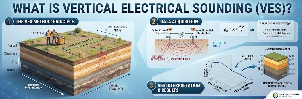
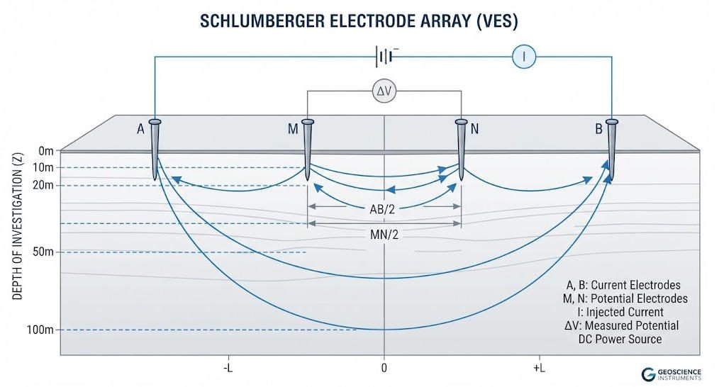
VES measures how electrical resistivity changes with depth at a single surface point. The technique uses four electrodes arranged in a straight line. Two outer electrodes inject direct current into the ground. Two inner electrodes measure the resulting voltage difference.
By gradually increasing the spacing between current electrodes, the current penetrates deeper layers. Each spacing yields one apparent resistivity value. A complete sounding produces a curve of apparent resistivity versus half-current electrode spacing (AB/2). Inversion software then converts this curve into a one-dimensional layered model.
The most common configuration is the Schlumberger array. Only the outer current electrodes move during acquisition. The inner potential electrodes remain fixed until a spacing threshold is reached. This design reduces field labor and improves vertical resolution.
2. Typical Applications
VES excels in scenarios where horizontal layering dominates. Common applications include:
- Groundwater exploration in sedimentary basins
- Depth-to-bedrock estimation for foundation design
- Aquifer thickness and resistivity profiling
- Preliminary reconnaissance before detailed surveys
Field crews can complete a single sounding in 30 to 90 minutes. Equipment is lightweight and requires no external power source beyond a small transmitter battery. These factors make VES the go-to method for remote regions with limited infrastructure.
3. Key Limitations
VES assumes that geology is horizontally layered and laterally uniform. This assumption fails in complex terrain. The method also suffers from the equivalence problem. Different combinations of layer thickness and resistivity can produce nearly identical sounding curves. Geophysicists must validate VES results with borehole data or independent geophysical evidence.
Lateral resolution is essentially zero. A VES station provides no information about conditions five meters to the left or right. For projects that require spatial mapping, VES alone is insufficient.
Ⅲ. From VES to ERT: The Technological Evolution
1. The Data Density Revolution
The jump from VES to ERT is not incremental. It is a paradigm shift. Consider the numbers.
A conventional VES survey collects one data point per electrode spacing. A typical sounding might include 15 to 25 spacings. A modern ERT system with 64 electrodes can collect 200,000 or more data points in a single day. This exponential increase in data density transforms interpretation confidence.
| Parameter | Conventional VES | Modern ERT System |
|---|---|---|
| Dimension | 1D vertical profile | 2D cross-section or 3D volume |
| Electrode count | 4 | 24 to 120+ |
| Daily data points | 15–25 per sounding | 200,000+ |
| Spatial resolution | None (single point) | 0.5 m to 2 m |
| Depth penetration | 10–500 m | 10–1,500 m |
| Field deployment | Manual copper rods | Wireless IP68 nodes |
| Inversion algorithm | 1D curve matching | 3D CNN deep learning |
2. Hardware Evolution
Early VES instruments used analog galvanometers and manual electrode placement. Crews hammered copper rods into the ground and moved them by hand. Data logging was paper-based. Inversion required graphical curve matching with master charts.
Modern ERT systems bear little resemblance to those ancestors. Wireless nodes communicate over LoRa networks spanning 500 meters. Each node contains a 24-bit analog-to-digital converter. Measurement resolution reaches 0.1 microvolts. Adaptive current control adjusts output from 10 milliamps to 3 amps automatically. This dynamic range enables consistent signal quality across variable ground conditions.
IP68-rated enclosures protect electronics from dust and immersion. Operating temperature ranges from minus 20 degrees Celsius to plus 60 degrees Celsius. These specifications allow year-round deployment in deserts, tropical wetlands, and alpine environments.
3. Algorithm Advancement
Inversion is the mathematical process that converts measured voltages into a resistivity model. Traditional VES inversion relied on one-dimensional layer-stripping algorithms. These methods were fast but restrictive. They could not handle lateral property changes.
Modern ERT inversion uses two-dimensional or three-dimensional finite-element or finite-difference methods. Some advanced systems incorporate convolutional neural networks trained on synthetic and field datasets. These deep-learning algorithms reduce inversion error to approximately plus or minus four percent. They also process data in minutes rather than hours.
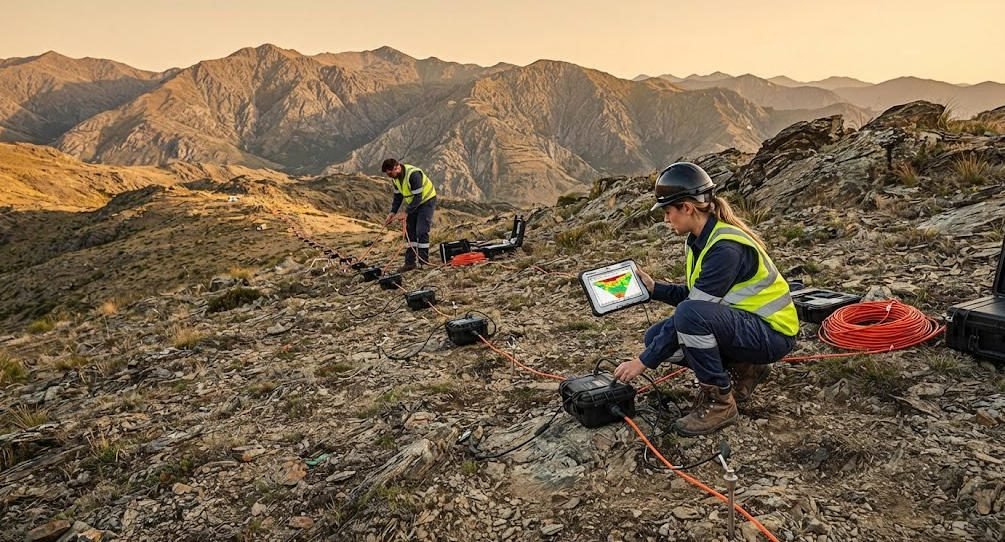
Real-time quality assurance is another breakthrough. Field crews can view preliminary inversion results on tablets within seconds of data acquisition. This instant feedback reduces field rework by up to 68 percent. Teams spot bad electrode contacts, array geometry errors, and noise spikes before leaving the site.
Ⅳ. How Modern ERT Systems Work
1. Multi-Channel Acquisition
A multi-channel resistivity meter connects to an array of electrodes through a switching unit. The system automatically selects combinations of current and potential electrodes according to a programmed sequence. Common sequences include Wenner, Schlumberger, dipole-dipole, and gradient arrays.
Multi-channel architecture is the key to speed. Instead of measuring one electrode pair at a time, the system measures multiple pairs simultaneously. A 64-channel instrument can acquire data up to 80 times faster than a single-channel VES setup. This speed matters when survey lines stretch for kilometers or when time-lapse monitoring requires repeated measurements.
2. Array Configuration Strategy
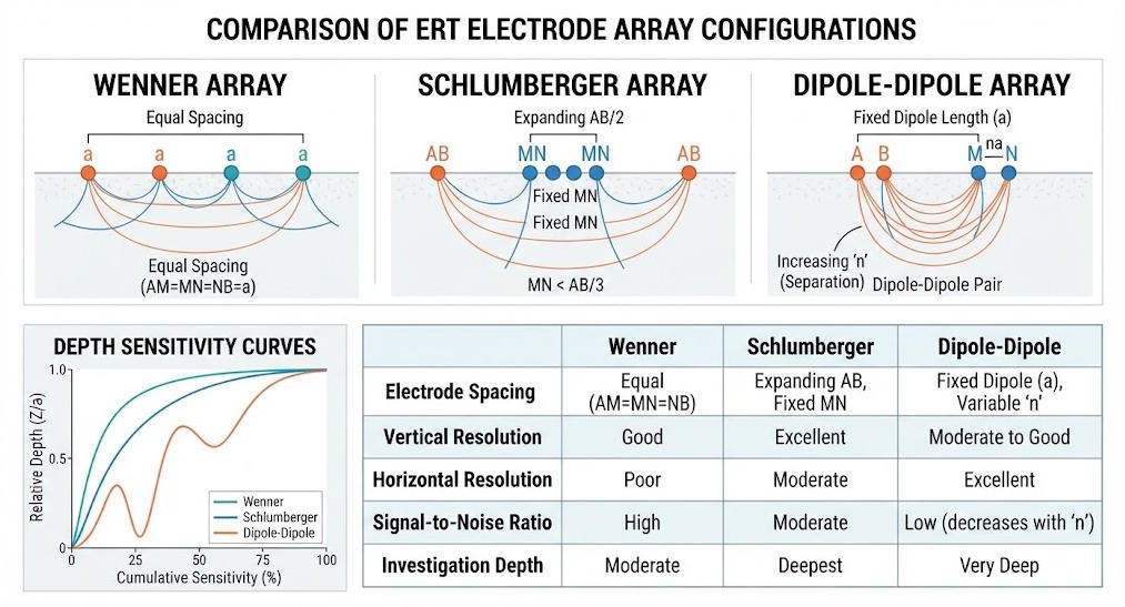
Array selection depends on the geological target. The Wenner array provides strong signal amplitudes and is robust against noise. It works well for shallow groundwater investigations. The Schlumberger array offers better depth penetration with less cable. It is preferred for deep basement studies. The dipole-dipole array provides superior lateral resolution. It excels at mapping steeply dipping faults and vein structures.
Hybrid arrays combine configurations within a single survey. For example, a Wenner-Schlumberger hybrid might use Wenner spacing for shallow sections and Schlumberger spacing for deep sections. This approach optimizes both resolution and depth of investigation.
3. 3D Volume Modeling
Three-dimensional ERT requires electrode grids rather than linear profiles. Electrodes are placed in rectangular or irregular patterns. The acquisition software records measurements between all possible electrode combinations within the grid. Inversion produces a volumetric resistivity model.
Three-dimensional ERT is essential for complex geology. Porphyry copper deposits, karst terrain, and urban brownfield sites all require volumetric imaging. A 3D model allows geoscientists to slice the volume at any depth or orientation. They can track contamination plumes, map cavity networks, and plan drill holes with confidence.
Ⅴ. Engineering Applications and Case Studies
1. Groundwater Exploration
Electrical methods remain the dominant geophysical approach for groundwater assessment. Low-resistivity zones typically indicate saturated porous formations, weathered rock containing water, or clay-rich layers. ERT provides the spatial detail needed to locate well sites and estimate aquifer geometry.
In the Cordillera Blanca region of Peru, researchers combined ERT with VES and seismic refraction. They mapped depth to saturation and bedrock geometry in alpine valleys. Average depth to bedrock was 25 meters. Water table depths varied across the valley. These data informed groundwater flow models for glacier-fed watersheds.
2. Mineral Exploration
Porphyry copper and epithermal gold deposits exhibit distinct resistivity signatures. Alteration halos around ore bodies create conductive zones that ERT can map. In Chile’s porphyry copper belt, ERT distinguishes argillic alteration from phyllic alteration. This information guides drill targeting with a precision that single-point methods cannot match.
Induced polarization (IP) surveys complement ERT in mineral exploration. IP measures the chargeability of subsurface materials. High chargeability indicates disseminated sulfide minerals. Modern systems like the GIM Series acquire both resistivity and IP data in a single deployment. This dual-mode capability reduces field time and provides complementary physical parameters.
3. Karst and Cavity Detection
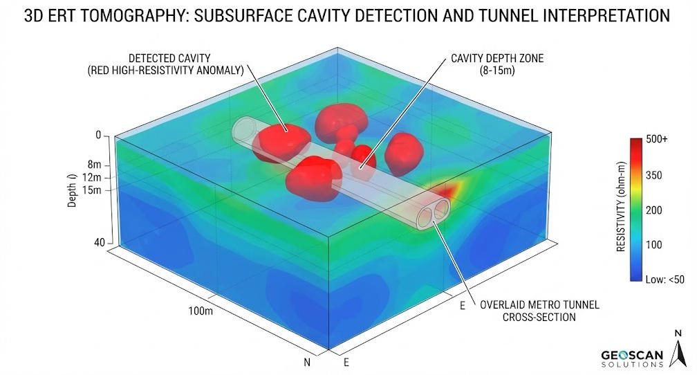
Karst terrain poses serious risks to construction and infrastructure. Subsurface cavities can collapse without warning. Traditional VES methods struggle to detect small or laterally offset voids.
A case study from Shanghai demonstrates the advantage of modern ERT. A metro extension project initially used conventional VES and missed three cavities. The project team then deployed a high-density ERT system with a Wenner-Schlumberger hybrid array. The system surveyed 3.2 kilometers of line at a rate of 420 points per minute. Detection accuracy improved from 64 percent to 98 percent. Positioning accuracy improved from plus or minus 8.2 meters to plus or minus 0.7 meters. Project costs dropped by 45 percent.
4. Environmental and Engineering Geophysics
ERT maps contaminant plumes, landfill boundaries, and leachate migration pathways. It monitors dam integrity and tailings storage facilities. It profiles landslide geometry and identifies potential sliding surfaces.
In landslide monitoring, time-lapse ERT tracks seasonal groundwater fluctuations. Changes in resistivity reveal saturation zones that correlate with movement events. Engineers use this information to design drainage systems and early warning networks.
Ⅵ. Choosing Between VES and ERT
1. When VES Is the Right Choice
VES remains valuable for specific scenarios. Choose VES when:
- Budget constraints limit equipment rental
- The target is a simple layered aquifer or bedrock interface
- The survey area is remote and logistics favor lightweight gear
- The project requires rapid reconnaissance across a large region
- Only depth information is needed, not lateral detail
VES is also an excellent precursor to ERT. A sparse grid of VES soundings can identify zones of interest. Targeted ERT profiles then provide detailed imaging in those zones. This two-stage approach optimizes both cost and data quality.
2. When ERT Is Essential
ERT is non-negotiable for complex projects. Deploy ERT when:
- Geology is known to vary laterally
- The target is a fault, dike, or cavity with unpredictable geometry
- Contaminant plumes or alteration zones require spatial mapping
- Three-dimensional drill targeting is required
- Time-lapse monitoring tracks dynamic processes
Modern ERT systems have narrowed the cost gap. Multi-channel acquisition reduces labor hours. Wireless nodes eliminate cable management delays. For most mid-scale projects, the additional data quality justifies the incremental expense.
3. Integration with Complementary Methods
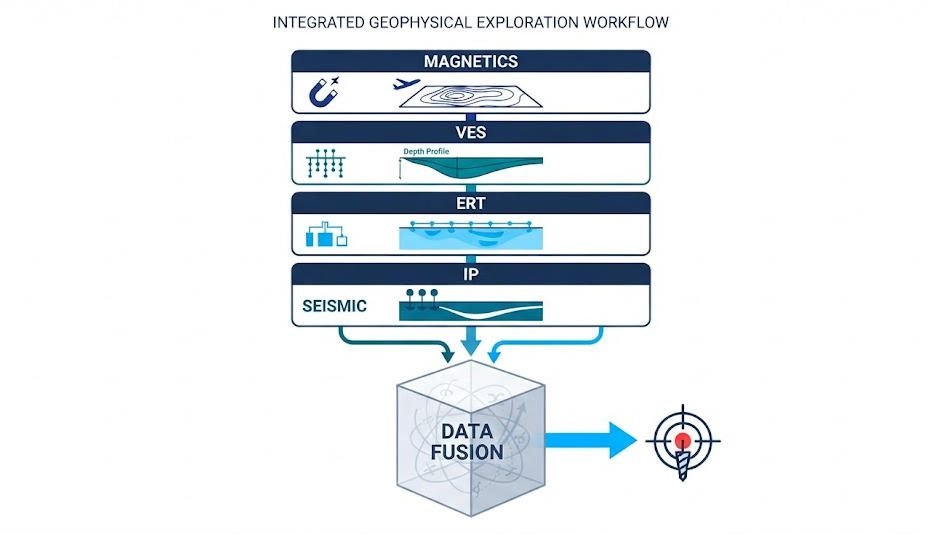
No single geophysical method solves every problem. Smart exploration teams integrate multiple techniques. A typical integrated workflow might include:
- Magnetics for regional structure and intrusive body mapping
- VES for initial depth-to-bedrock and water table estimates
- ERT for conductive zone delineation and spatial imaging
- IP for sulfide identification and clay discrimination
- Seismic refraction for detailed depth-to-bedrock and rock quality
Data fusion platforms merge these datasets. Artificial intelligence algorithms identify anomalies that satisfy multiple physical criteria. The result is sharper targeting and improved drilling success rates.
Ⅶ. Conclusion
The evolution from vertical electrical sounding to electrical resistivity tomography represents one of the most significant advances in near-surface geophysics. VES laid the groundwork with simple, robust one-dimensional profiling. ERT builds on that foundation with multi-channel acquisition, wireless deployment, and three-dimensional inversion.
Modern systems like the GIM Series combine VES, 2D ERT, 3D ERT, and IP capability in a single platform. Ten-channel synchronous acquisition and rolling measurement mode cover long profiles without stopping. IP67-rated hardware operates in extreme environments. Export formats compatible mainstream inversion software including Res2DInv and EarthImager.
For exploration managers and geophysical contractors, the message is clear. Understand your geological target. Match the method to the complexity. Use VES for reconnaissance and depth estimation. Use ERT for detailed spatial imaging. Combine both when budgets and timelines allow. The right technology choice transforms uncertain ground into actionable subsurface intelligence.
Reference Sources
FAQ
Q1: What is the difference between VES and ERT?
VES is a one-dimensional method. It measures resistivity with depth at a single point using four electrodes. ERT is a multi-dimensional method. It maps lateral and vertical variations using 24 to 120 or more electrodes. VES is faster and cheaper for depth estimation. ERT provides superior spatial resolution for complex geology.
Q2: How deep can ERT and VES investigate?
Investigation depth depends on electrode spacing and array type. A common rule states that effective depth equals one-third to one-fifth of the total array length. Typical VES surveys reach 10 to 500 meters. Modern ERT systems with cascading technology achieve 1,500 meters. High-resolution urban surveys may target only 10 to 30 meters.
Q3: Which electrode array is best for resistivity surveys?
The Schlumberger array is the most popular choice for VES. It offers good vertical resolution and requires less field labor. For ERT, the Wenner array provides strong signals for shallow targets. The dipole-dipole array offers better lateral resolution for steep structures. Hybrid arrays optimize both depth and resolution in a single survey.
Q4: Can ERT detect groundwater and cavities at the same time?
Yes. A single ERT survey images the entire resistivity distribution beneath the electrode array. Low-resistivity zones may indicate saturated aquifers or clay layers. High-resistivity zones may indicate fresh bedrock, air-filled cavities, or dry sand. Interpretation requires geological context. Induced polarization data help distinguish clay from water-bearing zones.
Q5: How much does a geophysical resistivity survey cost?
Costs vary with survey size, terrain, and method. A VES reconnaissance program might cost 40 percent less than an equivalent drilling campaign. ERT surveys require more equipment and labor but reduce overall project risk. The Shanghai metro case study demonstrated a 45 percent cost reduction when switching from conventional VES to high-density ERT. The key metric is cost per reliable data point, not just field-day rate.