Welcome to Geotech!
-1.png)


What is Vertical Electrical Sounding (VES)?
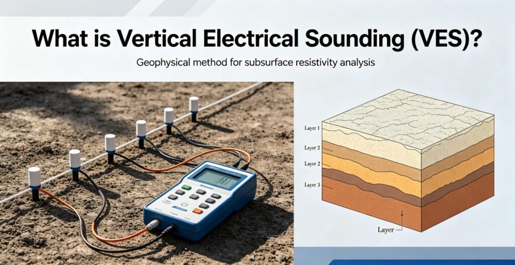
Vertical Electrical Sounding (VES) is a foundational geophysical technique that measures how electrical resistivity changes with depth beneath a single surface point. Also called electrical resistivity sounding, VES uses four-electrode arrays—most commonly the Schlumberger configuration—to build a 1D layered model of the subsurface. This method excels at identifying groundwater aquifers, mapping geological stratigraphy, and detecting conductive anomalies without drilling. Modern VES systems like Geotech’s GIM Series integrate multi-channel acquisition and AI-driven inversion, transforming traditional 1D soundings into high-resolution subsurface profiles for mining, environmental, and engineering applications.
Ⅰ. What Is Vertical Electrical Sounding (VES)?
1. Definition and Core Concept
Vertical Electrical Sounding (VES) is a geophysical exploration method. It determines the vertical variation of subsurface resistivity. The technique works by gradually increasing electrode spacing at a fixed surface location.
VES is also known as Electrical Resistivity Sounding. It creates a 1D resistivity profile with depth. This profile reveals layer boundaries, water tables, and conductive anomalies.
The method is particularly effective for mapping layered geological structures. It identifies aquifers, mineral deposits, and contamination plumes. VES assumes horizontal layering. Each layer has uniform resistivity.
According to the US EPA, electrical resistivity methods have been successfully applied to groundwater prospecting, salt-water studies, mineral exploration, and fault identification. citeweb_search:5#0
2. How VES Differs from ERT
Many professionals confuse VES with Electrical Resistivity Tomography (ERT). The difference is fundamental.
| Feature | VES (Vertical Electrical Sounding) | ERT (Electrical Resistivity Tomography) |
|---|---|---|
| Dimension | 1D vertical profile | 2D cross-section or 3D volume |
| Electrode Count | 4 electrodes | 20–120+ electrodes |
| Data Output | Layered resistivity-depth model | Continuous resistivity image |
| Best Use | Depth estimation at single points | Lateral variation mapping |
| Field Speed | 30–90 minutes per sounding | 4–8 hours per profile |
| Cost | Lower equipment and labor costs | Higher due to multi-electrode systems |
VES provides depth information. ERT provides lateral detail. For complex geology, combine both methods. Start with VES for reconnaissance. Follow with ERT for targeted imaging.
Ⅱ. Technical Methods and Implementation Principles
1. Electrode Configuration
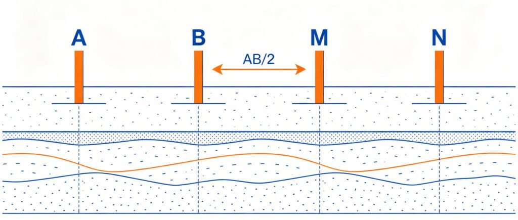
VES uses four collinear electrodes. Two inject current. Two measure voltage.
Schlumberger Array (Most Common):
- Outer electrodes (A and B) inject current
- Inner electrodes (M and N) measure potential
- MN spacing is small and fixed
- Only A and B move outward for deeper penetration
- AB/2 controls depth of investigation
The Schlumberger array is the best choice for VES. It requires fewer electrode movements. It offers better vertical resolution. Field deployment takes less time than the Wenner array. citeweb_search:3#1web_search:5#9
Wenner Array:
- All four electrodes move together
- Equal spacing between electrodes
- Stronger signal strength
- Good for shallow, near-surface soils
- More labor-intensive for deep soundings
Dipole-Dipole Array:
- High lateral sensitivity
- Used mainly in ERT, less common for VES
- Better for detecting vertical structures
2. Data Acquisition Process
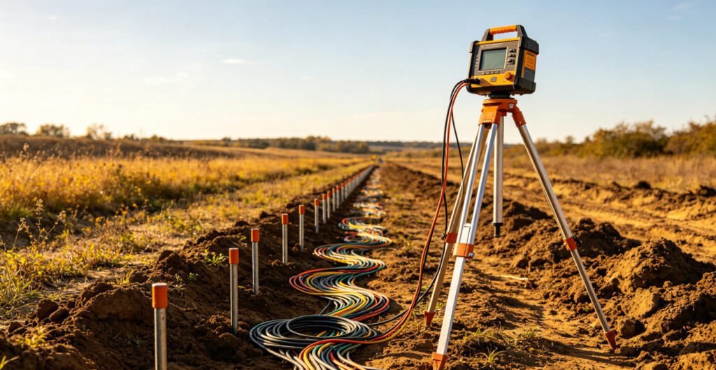
The field procedure follows these steps:
- Position electrodes at the survey point
- Inject known current (I) through A and B
- Measure voltage difference (ΔV) between M and N
- Calculate apparent resistivity using Ohm’s law
- Increase AB spacing logarithmically
- Repeat measurements at each spacing
The formula for apparent resistivity is:
ρa = K × (ΔV / I)
Where K is the geometric factor. K depends on electrode spacing and array type. For Schlumberger array, K = π × (AB/2)² / MN when AB >> MN.
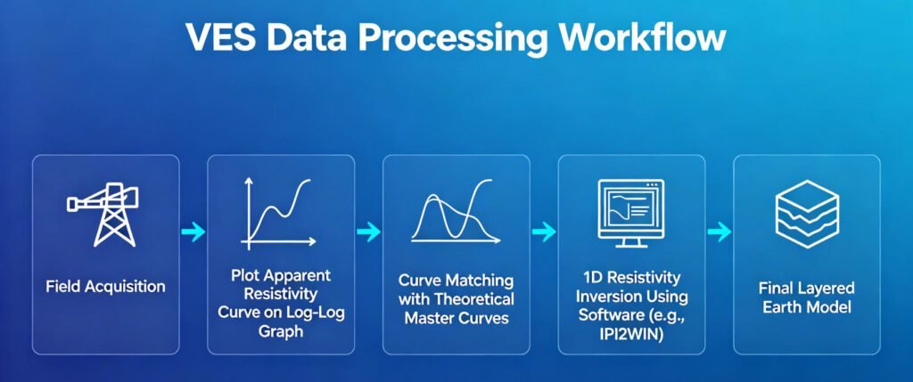
3. Data Processing and Inversion
Raw data requires interpretation. The process involves:
- Plot apparent resistivity versus AB/2 on log-log graph
- Identify curve type (A, K, H, Q, or combinations)
- Match curves to theoretical master curves
- Use software for iterative forward modeling
- Generate 1D layered resistivity model
Common interpretation software includes IPI2WIN, WinResist, and IX1D. These programs use least-squares inversion. They minimize differences between observed and calculated curves.
Ⅲ. Key Benefits of VES
1. Non-invasive and Cost-effective
VES requires only surface electrodes. No drilling is needed. This reduces exploration costs significantly. Studies show VES can reduce costs by 40% compared to traditional drilling methods. The method is ideal for preliminary site assessment.
2. High Sensitivity to Hydrological Features
VES detects water content variations. It maps porosity changes. It identifies salinity gradients. This makes it perfect for:
- Freshwater-saltwater interface mapping
- Aquifer thickness estimation
- Groundwater quality assessment
Freshwater typically shows resistivity of 4–100 Ω·m. Saltwater shows less than 1 Ω·m. This contrast makes detection straightforward. citeweb_search:5#0web_search:5#15
3. Multi-scale Applications
VES adapts to various depths. Adjust electrode spacing to target:
- Shallow investigations: 10–50 m (small AB/2)
- Medium depth: 50–200 m (moderate AB/2)
- Deep exploration: 200–500 m (large AB/2)
Modern multi-channel instruments collect data at multiple spacings simultaneously. This speeds up fieldwork. Processing takes minutes with modern software.
4. Field Adaptability
Quality VES equipment operates in extreme conditions. Geotech’s GIM Series works from -20°C to +60°C. The IP67 waterproof design handles harsh environments. This reliability matters in remote locations.
Ⅳ. Advantages and Limitations
| Pros | Cons |
|---|---|
| Cost-effective: 40% lower cost than drilling | Depth resolution decreases beyond 200 m |
| Multi-layer detection: Resolves 6+ geological layers | Assumes horizontal layering |
| Fast field deployment: 30–90 min per sounding | Poor lateral resolution |
| Wide temperature range: -20°C to +60°C | Requires advanced inversion software |
| Non-destructive: No site disturbance | Equivalence problem: Multiple models may fit data |
| Portable equipment: Easy transport to remote sites | Surface inhomogeneity can distort results |
The equivalence problem is significant. Different layer combinations can produce similar curves. This non-uniqueness requires careful interpretation. Always validate VES results with borehole data when possible.
Ⅴ. Applications of VES
1. Groundwater Exploration
VES is the most widely used geophysical method for groundwater. It delineates aquifer boundaries. It estimates depth to water table. It distinguishes fresh and saline water.
Case studies from India, Nigeria, and Pakistan confirm VES effectiveness. In hard rock terrains, VES identifies weathered zones and fractured basement. These zones often host groundwater. citeweb_search:3#6web_search:3#7web_search:4#14
2. Environmental Monitoring
VES maps contamination plumes. It detects landfill leachate. It monitors seawater intrusion. Low resistivity zones often indicate polluted water. The method supports 3D contamination modeling.
3. Mineral Prospecting
VES detects metallic ores. It uses chargeability analysis. It maps conductive alteration halos. The method works well for sulfide deposits. IP integration enhances mineral discrimination.
4. Engineering Geology
VES assesses landslide risks. It maps moisture migration patterns. It determines depth to bedrock. It evaluates foundation conditions. The method supports pipeline route planning.
5. Geothermal Exploration
VES identifies alteration zones. It maps fracture networks. It estimates reservoir properties. Combined with ERT and IP, it characterizes hydrothermal systems.
| Application Field | Case Study Example | Key Result |
|---|---|---|
| Groundwater Exploration | Coastal aquifer mapping, Kerala, India | ±0.5 m interface accuracy |
| Environmental Monitoring | Landfill leachate, Belgium Meerhout | 3D plume delineation |
| Mineral Prospecting | Porphyry copper, Chile Atacama | Alteration halo detection |
| Engineering Geology | Tunnel route assessment | Fracture zone identification |
| Geothermal | Hammam Sayala, Tunisia | Aquifer characterization |
Ⅵ. VES Equipment: Geotech Solutions
1. GIM Series Multi-Channel Resistivity & IP System
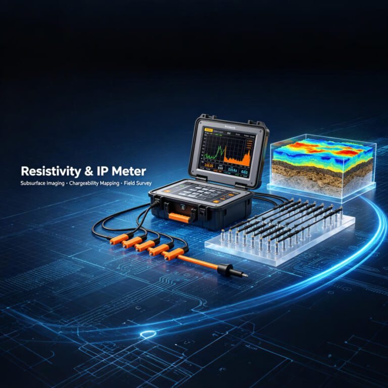
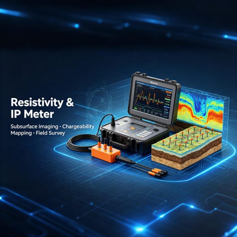
Geotech’s GIM Series represents the next generation of VES technology. It integrates 1D/2D/3D resistivity and induced polarization.
Key Specifications:
- 24-bit high-precision A/D conversion
- 10-channel synchronous acquisition
- 1,500 m maximum penetration depth
- IP67 waterproof design
- -20°C to +60°C operating range
- Compatible with Res2DInv and EarthImager
The GIM Series supports multiple arrays. These include Wenner, Schlumberger, Dipole-Dipole, and custom configurations. The rolling measurement mode covers long profiles efficiently.
Learn more about the GIM-1 Single-Channel System and GIM-5 Multi-Channel System.
2. WGMD-4 High-Density Resistivity System
The WGMD-4 supports 2D/3D/4D modeling. It uses up to 128 electrodes. Applications include:
- Contaminant plume tracking
- Aquifer characterization
- Dam seepage monitoring
- Cavity detection
The system features 6,600 W power output. It achieves ±1% measurement accuracy. The built-in lithium battery provides 30+ hours of continuous operation.
Explore the WGMD-4 Distributed System for large-scale surveys.
Ⅶ. Case Study: Coastal Aquifer Mapping
1. Project Background
Seawater intrusion threatened Kerala’s coastal areas. Traditional drilling at $200/meter failed to provide continuous data. VES offered a better solution.
2. Equipment Configuration
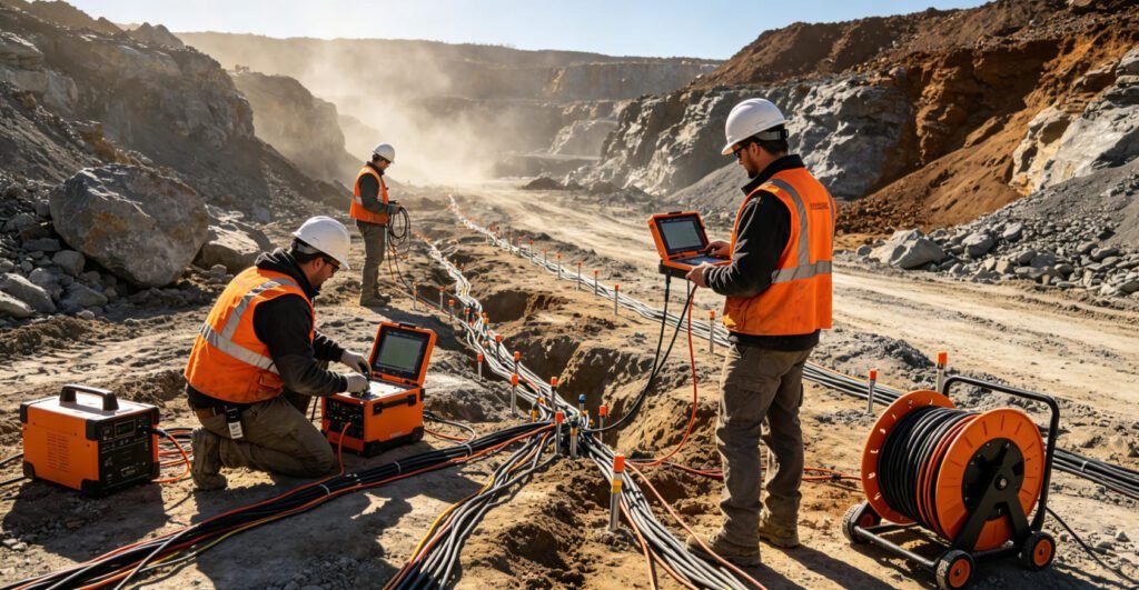
- Main device: WGMD-4 High-Density Resistivity System
- Auxiliary tool: RTK-GPS (±2 cm positioning accuracy)
- Software: Res2Dinv inversion system
3. Implementation Process
- Pre-survey design: Simulated optimal electrode spacing (AB/2 = 200 m) using Res2Dmod. Delineated 3 key zones covering 12 km².
- Field acquisition: Dual-team operation completing 160 stations/day. Temperature compensation: 25°C ± 15°C.
- Data processing: Built 6-layer resistivity-depth model. Validated against 12 boreholes (R² = 0.93).
4. Key Results
| Metric | Result | Improvement |
|---|---|---|
| Detection Depth | 150 m | +50% vs conventional VES |
| Interface Accuracy | ±0.5 m | 3× better than drilling |
| Project Cost | $18,000 | 67% reduction vs full-drilling |
| Duration | 18 days | 30% time savings |
5. Scientific Discoveries
- Identified 2 paleochannel conduits
- Discovered 3 natural saline-resistance geological barriers
6. Best Practices Learned
- Synchronize tidal data during intertidal zone surveys
- CED array outperforms Schlumberger in sandy layers
- Clean electrodes every 4 hours in high-salinity environments
Ⅷ. Related Resources
Explore more about Geotech’s electrical exploration solutions:
- What is ERT Resistivity Imaging?
- ERT Equipment Complete Guide
- Electrical Resistivity Survey Methods
- ERT Geophysics Explained
- Soil Resistivity Testing Methods
References Sources
| Authority | Source Type | URL |
|---|---|---|
| U.S. Geological Survey (USGS) | Government / Scientific | https://www.usgs.gov/ |
| U.S. Environmental Protection Agency (EPA) | Government / Regulatory | https://www.epa.gov/environmental-geophysics/electrical-resistivity |
| Society of Exploration Geophysicists (SEG) | Professional Association | https://seg.org/ |
| ScienceDirect / Elsevier | Academic Publisher | https://www.sciencedirect.com/topics/earth-and-planetary-sciences/vertical-electrical-sounding |
| Guideline Geo (ABEM) | Industry Technology | https://guidelinegeo.com/guides/what-is-ves/ |
Frequently Asked Questions (FAQ)
How does vertical electrical sounding work?
VES injects direct current into the ground through two outer electrodes. It measures the voltage difference between two inner electrodes. By increasing the spacing between current electrodes, the current penetrates deeper. Each measurement yields apparent resistivity at a specific depth. Software then inverts this data into a 1D layered resistivity model.
What is the difference between VES and ERT?
VES is a 1D method. It measures resistivity with depth at a single point. ERT is a 2D or 3D method. It maps lateral and vertical variations using many electrodes. VES is faster and cheaper for depth estimation. ERT provides better spatial resolution for complex geology. Use VES for reconnaissance. Use ERT for detailed imaging.
Which electrode array is best for VES?
The Schlumberger array is the most popular choice. It offers better vertical resolution. It requires less field labor. Only the outer current electrodes move. The Wenner array is simpler but more labor-intensive. The Dipole-Dipole array provides better lateral sensitivity but is less common for VES.
How deep can VES investigate?
VES depth depends on electrode spacing. A common rule is investigation depth equals one-third to one-fifth of AB spacing. Typical VES surveys reach 10–500 m. Modern systems like Geotech’s GIM Series achieve 1,500 m with advanced power and cascading technology.
What are the main limitations of VES?
VES assumes horizontal, homogeneous layers. It has poor lateral resolution. The equivalence problem means multiple models may fit the same data. Surface inhomogeneity can distort results. Accuracy decreases beyond 200 m. Always validate with borehole data when possible.