Welcome to Geotech!
-1.png)


What Is Geoelectrical Monitoring?丨Geoelectrical Monitoring: Methods & Systems
Overview:Geoelectrical Monitoring tracks changes in subsurface electrical properties through repeated electrical measurements. It helps engineers investigate moisture movement, groundwater dynamics, slope conditions, and environmental changes. This guide explains how Geoelectrical Monitoring works, how geoelectrical investigations support long-term site assessment, and how to select a suitable monitoring system for engineering and environmental projects.
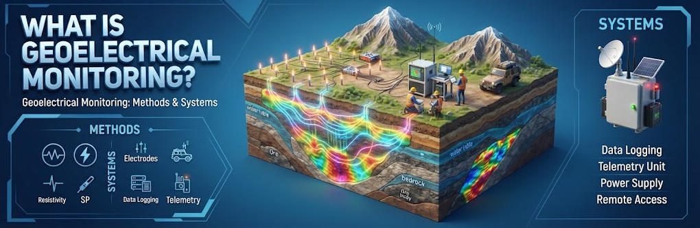
Ⅰ. What Is Geoelectrical Monitoring?
Geoelectrical monitoring is the repeated measurement of subsurface electrical properties to track changes in geological, hydrological, or environmental conditions over time. It commonly uses electrical resistivity or related electrical methods to identify changes in moisture, fluid distribution, and subsurface structure.
Unlike a one-time geophysical survey, monitoring focuses on how the subsurface changes between measurement periods. Engineers compare successive datasets to distinguish persistent geological features from time-dependent variations.
Geoelectrical monitoring can support slope investigations, groundwater studies, infrastructure assessment, and environmental management. It complements direct measurements rather than replacing them.
1. Geoelectrical Monitoring vs. Geoelectrical Investigations
Geoelectrical investigations use electrical measurements to characterize subsurface properties. Geoelectrical monitoring extends this approach by repeating measurements to track changes.
| Feature | Geoelectrical Investigations | Geoelectrical Monitoring |
|---|---|---|
| Primary Objective | Characterize subsurface electrical properties | Track changes in electrical properties over time |
| Measurement Schedule | Usually a survey campaign | Repeated or continuous acquisition |
| Main Outputs | Resistivity sections, soundings, and models | Baseline models, time-lapse sections, and change maps |
| Typical Applications | Geological mapping, groundwater exploration, site characterization | Slope monitoring, seepage assessment, groundwater dynamics |
| Main Interpretation Focus | Spatial variation | Spatial and temporal variation |
A baseline investigation is often the first stage of a monitoring program. It establishes the initial electrical structure against which later measurements can be compared.
2. What Does Geoelectrical Monitoring Measure?
The primary measurement in direct-current resistivity monitoring is electrical potential difference under a controlled current injection. The system uses the current, voltage, and electrode geometry to calculate apparent resistivity.
The resulting electrical images represent changes in subsurface electrical properties. These changes may relate to:
- Variations in water content and saturation
- Changes in pore-water salinity or ionic concentration
- Groundwater movement and hydraulic connectivity
- Changes in temperature
- Soil deformation or electrode movement
- Changes in geological or geotechnical conditions
The relationship between resistivity and a specific physical process depends on the material and site conditions. Resistivity changes should not be interpreted as direct measurements of water content, pore pressure, or displacement without appropriate calibration and supporting evidence.
Ⅱ. How Does the Geoelectrical Method Work?
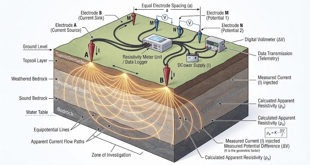
The geoelectrical method measures electrical responses within the ground using electrodes and controlled electrical signals. In resistivity surveys, current electrodes inject current, while potential electrodes measure voltage differences.
For a four-electrode measurement:
R=IΔV
The apparent resistivity is calculated as:
ρa=KIΔV
Where:
- ρa = apparent resistivity, in Ω·m
- K = geometric factor determined by the electrode configuration
- ΔV = measured voltage difference
- I = injected current
Apparent resistivity is a measurement-derived quantity. It does not necessarily equal the true resistivity of an individual subsurface layer.
1. Electrical Resistivity and Subsurface Conditions
Electrical current moves through soil and rock according to their electrical properties. In many near-surface materials, conduction occurs mainly through pore fluids and mineral-surface processes.
Water content, pore-water chemistry, clay content, porosity, and temperature can all influence electrical resistivity.
For example, an increase in water saturation may reduce resistivity when pore-water conductivity and other conditions remain sufficiently stable. However, the relationship is not universal.
2. From Resistivity Measurements to Time-Lapse Images
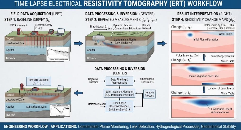
Time-lapse electrical resistivity tomography (TL-ERT) repeats resistivity measurements along a survey line or across a three-dimensional electrode array.
A typical workflow includes:
- Acquire a baseline resistivity dataset.
- Repeat measurements using the same or a compatible electrode configuration.
- Apply data-quality checks and correct known acquisition differences.
- Process and invert the datasets.
- Compare the resulting resistivity models or use time-lapse inversion.
- Evaluate changes alongside rainfall, groundwater levels, temperature, and displacement data.
The output is a time-dependent resistivity model. The model helps locate changes and track their development, but interpretation requires geological context and an understanding of measurement uncertainty.
Ⅲ. Main Geoelectrical Monitoring Methods
Different geoelectrical methods measure different electrical properties. The appropriate method depends on the target process and the required sensitivity.
1. Electrical Resistivity Monitoring
Electrical resistivity monitoring is widely used to investigate changes in the subsurface associated with moisture, groundwater, and fluid movement.
It can use surface electrodes, borehole electrodes, or a combination of both. The best configuration depends on target depth, site geometry, access, and the required spatial coverage.
2. Induced Polarization Monitoring
Induced polarization (IP) measures the delayed electrical response of subsurface materials after an electrical signal is applied.
Time-domain IP commonly evaluates chargeability, while spectral or complex-resistivity methods investigate frequency-dependent electrical behavior.
IP can provide information complementary to resistivity, particularly where mineral surfaces, pore structures, or electrochemical processes influence the response. Its usefulness depends on the geological setting and the monitoring objective.
3. Self-Potential Monitoring
Self-potential (SP) monitoring measures naturally occurring electrical potential differences in the ground without requiring the same current-injection process used in conventional resistivity surveys.
SP signals can be associated with fluid flow, electrochemical gradients, and other subsurface processes. Interpretation requires careful control of electrode stability, temperature effects, and environmental noise.
4. Comparing Geoelectrical Methods
| Method | Primary Measurement | Potential Monitoring Applications | Main Limitation |
|---|---|---|---|
| Electrical Resistivity | Voltage response to injected current | Moisture changes, groundwater movement, seepage-related changes | Resistivity is affected by several interacting variables |
| Induced Polarization | Chargeability or frequency-dependent response | Mineralogical changes and selected geochemical processes | Requires suitable signal quality and interpretation |
| Self-Potential | Natural electrical potential | Groundwater flow and electrochemical processes | Signals can be weak and sensitive to environmental effects |
| Complex Resistivity | Frequency-dependent electrical response | Pore-scale and geochemical investigations | Requires specialized acquisition and processing |
These methods can be combined when the project requires multiple types of subsurface information.
Ⅳ. Geoelectrical Monitoring System Components
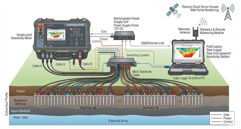
A monitoring system integrates field electrodes, measurement equipment, control and communications, and data-processing tools.
1. Electrode Arrays and Installation
Electrodes provide electrical contact between the instrument and the ground. Surface arrays are common in near-surface surveys, while borehole arrays can improve access to deeper or confined targets.
For long-term monitoring, electrodes should remain stable and maintain reliable contact with the ground. Installation design should account for site access, weather exposure, maintenance requirements, and potential ground movement.
2. Measurement and Switching Equipment
The measurement system supplies controlled current, records voltage responses, and manages electrode combinations.
A multi-electrode system may use switching hardware to automate measurement sequences. The required current output and voltage range depend on ground resistivity, electrode spacing, contact conditions, and system configuration.
3. Data Acquisition and Communication
Automated systems can schedule measurements and transfer data to a local server or remote platform.
Depending on the design, communication may use wired connections, cellular networks, or other telemetry options. Remote access does not remove the need for field inspections and data-quality checks.
4. Processing and Interpretation Software
Processing software checks the measurements and prepares datasets for inversion. Inversion software estimates a resistivity distribution that is consistent with the observations and the selected model assumptions.
Monitoring workflows may use independent inversion of each survey, difference imaging, or time-lapse inversion. The appropriate approach depends on data quality, site complexity, and the monitoring objective.
Ⅴ. How to Design a Geoelectrical Monitoring Program
A reliable monitoring program begins with a clearly defined physical process and a realistic understanding of site conditions.
1. Define the Monitoring Objective
Identify the process the project needs to observe.
| Monitoring Objective | Example Target | Supporting Data |
|---|---|---|
| Slope moisture changes | Water infiltration and drainage | Rainfall, soil moisture, displacement |
| Groundwater dynamics | Changes in saturated zones | Water levels, hydraulic data |
| Dam or embankment seepage | Potential changes in internal water distribution | Pore pressure, seepage flow, water level |
| Mine waste monitoring | Moisture and fluid-distribution changes | Pore pressure, drainage chemistry, deformation |
| Contaminant transport | Electrical changes associated with fluid migration | Groundwater sampling, chemistry, hydraulic gradients |
The monitoring objective determines electrode geometry, survey frequency, measurement method, and data interpretation strategy.
2. Establish a Baseline
A baseline survey characterizes the initial electrical structure before long-term monitoring begins.
It should include:
- Electrode locations and installation records
- Initial resistivity measurements
- Ground surface and geological observations
- Relevant hydrological and environmental conditions
- Instrument settings and acquisition parameters
- Baseline data-quality assessment
Where conditions vary naturally, multiple baseline measurements may help characterize normal variability.
3. Select Electrode Geometry
Electrode spacing and array geometry influence sensitivity, investigation depth, and spatial resolution.
Surface arrays may be suitable for shallow and laterally extensive targets. Borehole arrays can provide access to deeper structures or improve sensitivity within a selected volume.
The final layout should reflect the target geometry and the practical constraints of installation and maintenance.
4. Choose the Monitoring Frequency
Monitoring frequency should match the expected rate of change and the time required to collect reliable data.
| Monitoring Scenario | Scheduling Consideration |
|---|---|
| Rapid rainfall infiltration | More frequent acquisition during and after rainfall may be appropriate |
| Seasonal groundwater changes | Repeated measurements across relevant hydrological periods |
| Long-term slope assessment | Regular acquisition combined with event-based measurements |
| Mine waste facility monitoring | Frequency based on site risk, operational conditions, and monitoring objectives |
| Slow environmental changes | Periodic measurements supported by reference observations |
There is no universal monitoring interval. The acquisition schedule should balance process dynamics, measurement duration, data quality, and operational resources.
Ⅵ. Applications of Geoelectrical Monitoring
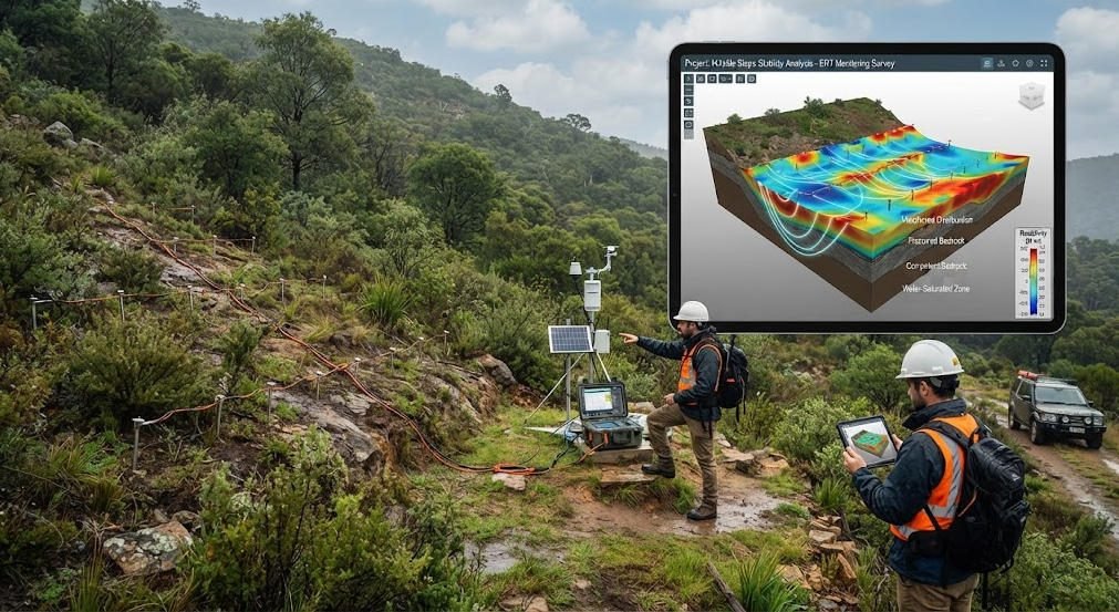
Geoelectrical monitoring can help investigate dynamic subsurface processes that point measurements alone may not fully describe.
1. Landslide and Slope Monitoring
Time-lapse resistivity imaging can track electrical changes associated with moisture movement within a slope. It may help identify zones where wetting, drainage, or internal heterogeneity evolves over time.
A study of monitored landslide sites reported resistivity decreases before observed displacement events. This finding illustrates a possible relationship at those sites, not a universal landslide precursor.
For engineering use, resistivity monitoring should be integrated with displacement sensors, rainfall measurements, groundwater observations, and geotechnical assessment.
2. Dam and Embankment Monitoring
Geoelectrical monitoring can help investigate changes in moisture distribution and seepage-related processes within embankments and earth structures.
Repeated resistivity measurements may identify evolving electrical anomalies that warrant further investigation. However, resistivity alone cannot confirm leakage, internal erosion, or structural failure.
The monitoring program should incorporate piezometers, seepage observations, deformation measurements, and engineering inspection where appropriate.
3. Groundwater and Hydrogeological Monitoring
Time-lapse resistivity imaging can track changes associated with groundwater recharge, infiltration, surface-water interaction, and tracer movement.
The technique provides spatial information between conventional observation points. USGS research has demonstrated the use of time-lapse electrical imaging to study groundwater–surface-water interactions and changing subsurface conductivity patterns.
Interpretation should account for changes in water chemistry, temperature, and saturation.
4. Mining Waste and Tailings Monitoring
Mine waste facilities can experience changes in moisture distribution, drainage, and geochemical conditions.
Time-lapse ERT can complement conventional monitoring by providing spatial information about electrical changes within waste materials. A review published in 2022 examined applications of time-lapse ERT to mining waste monitoring and discussed opportunities and challenges for long-term autonomous systems.
Monitoring should be integrated with facility-specific geotechnical, hydrological, and geochemical observations.
5. Environmental and Contaminant Monitoring
Electrical resistivity monitoring can help track changes associated with fluid movement, saline intrusion, and some remediation processes.
It can support the interpretation of tracer movement or changes in subsurface conductivity. However, it cannot identify a specific contaminant or establish its concentration without independent evidence.
Groundwater sampling, chemical analysis, and hydrogeological data remain important for confirming environmental conditions.
Ⅶ. Data Processing, Inversion, and Interpretation
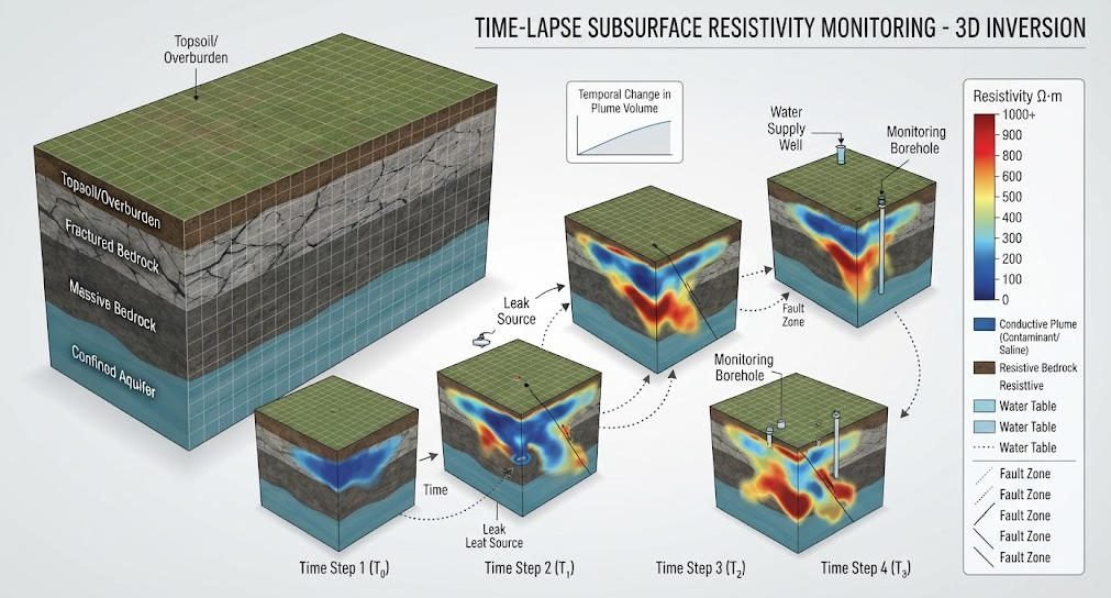
Reliable interpretation requires consistent acquisition, careful processing, and an understanding of what the electrical model represents.
1. Baseline and Time-Lapse Inversion
Independent inversion processes each dataset separately. Time-lapse inversion incorporates relationships between datasets to estimate changes over time.
| Approach | Main Purpose | Considerations |
|---|---|---|
| Independent Inversion | Produce a resistivity model for each survey | Differences between models may include inversion-related effects |
| Difference Imaging | Highlight changes relative to a reference survey | Sensitive to acquisition consistency and reference quality |
| Time-Lapse Inversion | Estimate temporal changes while considering relationships between surveys | Requires suitable regularization and compatible datasets |
| 4D Inversion | Estimate changes across three spatial dimensions and time | Greater computational and data-quality demands |
The selected inversion approach should match the available data and the monitoring objective.
2. Understand Resistivity Changes
A resistivity change can reflect several physical processes.
For example, a resistivity decrease may be associated with increased saturation, more conductive pore water, or temperature-related changes. A resistivity increase may reflect drying, changes in fluid chemistry, or other material changes.
These relationships are site-dependent. A reliable interpretation requires a conceptual geological model and, where possible, calibration against direct measurements.
3. Separate Physical Changes from Measurement Artifacts
Potential sources of artifacts include:
- Electrode displacement
- Changes in electrode contact resistance
- Temperature variations
- Instrument drift
- Different electrode configurations
- Electrical interference
- Data gaps or inconsistent acquisition conditions
Electrode movement is especially important in long-term slope monitoring. Research has shown that uncorrected electrode movement can create artifacts in time-lapse resistivity images.
Monitoring systems should record electrode positions and inspect the consistency of the measurement setup.
Ⅷ. Geoelectrical Monitoring Equipment Selection
A suitable geoelectrical monitoring product should match the survey objective, field conditions, acquisition schedule, and data-processing workflow.
1. Compare System Architectures
| System Type | Typical Use | Advantages | Considerations |
|---|---|---|---|
| Manual Resistivity System | Periodic repeat surveys | Flexible and relatively simple deployment | Requires field personnel for each campaign |
| Multi-Electrode ERT System | Repeated 2D or 3D surveys | Supports dense spatial coverage | Requires electrode switching and suitable survey planning |
| Automated Monitoring System | Long-term scheduled measurements | Reduces the need for manual acquisition | Requires reliable power, communications, and maintenance |
| Borehole Geoelectrical System | Deeper or confined monitoring targets | Provides access to selected subsurface volumes | Installation and borehole access can increase complexity |
| Integrated Monitoring System | Projects requiring multiple data types | Combines electrical data with other measurements | Requires compatible timing, data management, and interpretation |
2. Key Technical Selection Criteria
| Selection Factor | Questions to Ask |
|---|---|
| Measurement Method | Does the project require resistivity, IP, self-potential, or a combination? |
| Output Capability | Can the system provide suitable current under expected ground conditions? |
| Electrode Configuration | Does it support the required surface or borehole array? |
| Channel and Switching Design | Can it acquire the required measurement sequence efficiently? |
| Long-Term Stability | Are the electrodes, connectors, and enclosure suitable for the environment? |
| Automation | Can measurements be scheduled and checked remotely? |
| Power and Communications | Are power supply and telemetry reliable at the site? |
| Data Processing | Does the workflow support repeatable inversion and comparison? |
| Maintenance | Can the system be inspected, calibrated, and serviced as required? |
A product should not be selected by channel count or output voltage alone. System performance depends on the complete measurement chain and site conditions.
3. Match the Product to the Monitoring Objective
| Project Requirement | Suggested Configuration |
|---|---|
| Periodic slope surveys | Portable resistivity system with a repeatable electrode layout |
| Dense monitoring along a slope | Multi-electrode ERT system with stable electrode installation |
| Long-term remote monitoring | Automated acquisition system with reliable telemetry and power |
| Groundwater monitoring | Surface or borehole ERT configured for the target aquifer |
| Combined resistivity and IP monitoring | Compatible resistivity/IP system with a suitable acquisition sequence |
The final configuration should be confirmed through site assessment and system-specific technical review.
Ⅸ. Common Challenges and Quality Assurance
Long-term geoelectrical monitoring involves more than collecting repeated measurements. It requires consistent field conditions, documented acquisition, and ongoing quality control.
1. Environmental Variability
Rainfall, temperature, water chemistry, and seasonal changes can alter electrical properties even when the target structure remains stable.
A monitoring program should record relevant environmental variables and distinguish expected seasonal behavior from changes that require investigation.
2. Electrode Stability
Electrodes may move due to ground deformation, erosion, frost, or construction activity.
A stable installation and periodic inspection help maintain measurement consistency. If electrode movement occurs, the acquisition geometry should be updated before interpreting changes.
3. Data Completeness and Consistency
Repeated surveys should use compatible electrode arrangements and measurement settings whenever possible.
Data gaps, changes in instrument configuration, and poor electrode contact should be documented. Quality-control procedures should identify unreliable measurements before inversion.
4. Interpretation and Alarm Design
A resistivity anomaly should not automatically trigger a safety conclusion.
Monitoring thresholds should be developed from site-specific baseline behavior, engineering criteria, and supporting measurements. Where monitoring supports hazard management, the system should be integrated into a broader risk-management and emergency-response framework.
Ⅹ. Geotech Geoelectrical Monitoring Product and Solutions
Geotech provides electrical exploration instruments and geophysical systems that can support resistivity surveys, electrical imaging, and related investigations.
For a monitoring project, the appropriate configuration depends on the required electrical method, electrode layout, survey frequency, target depth, and field conditions.
Relevant Geotech resources include:
- Electrical Imaging: ERT and VES
- What Are Resistivity Meters?
- Induced Polarization Method
- High Power IP System
- WDA-1 DC Meter
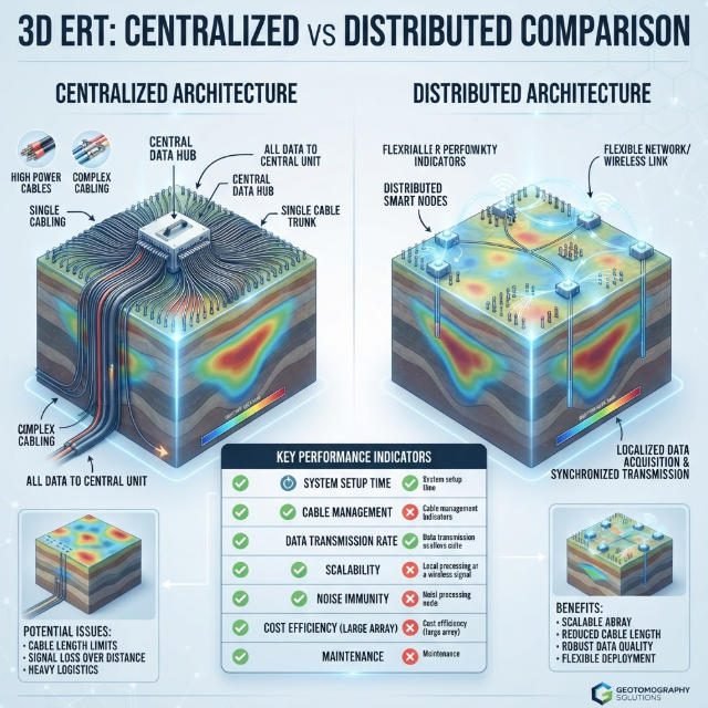
- WGMD-9 Distributed System
These resources provide a starting point for evaluating electrical survey equipment. A long-term monitoring configuration should be verified against the project’s specific acquisition, installation, and data-management requirements.
Ⅺ. Conclusion
Geoelectrical monitoring tracks changes in subsurface electrical properties through repeated measurements. It can help investigate moisture dynamics, groundwater movement, slope conditions, and environmental processes.
Time-lapse ERT is a major approach because it combines spatial imaging with repeated measurements over time. Reliable results require a well-designed baseline, stable electrodes, consistent acquisition, suitable inversion methods, and supporting geological or hydrological information.
For engineering and environmental projects, geoelectrical monitoring is most useful when integrated with conventional instrumentation and site-specific risk assessment. Equipment selection should begin with the monitoring objective and continue through system design, data quality, and long-term operational requirements.
Related Articles
| Title | Core Content | URL |
|---|---|---|
| Electrical Imaging: ERT & VES | Electrical resistivity imaging, vertical electrical sounding, and subsurface investigation | https://geotechcn.net/service/electrical-imaging-ert-ves/ |
| What Are Resistivity Meters? | Resistivity meter principles, measurement methods, and applications | https://geotechcn.net/service/what-are-resistivity-meters/ |
| Induced Polarization Method | IP principles, measurement techniques, and exploration applications | https://geotechcn.net/service/induced-polarization-ip/ |
| Geophysical Surveying Explained | Overview of geophysical methods and subsurface exploration | https://geotechcn.net/service/geophysical-surveying-explained/ |
| Geophysical Methods Demystified | Fundamentals of electrical, magnetic, seismic, and other geophysical methods | https://geotechcn.net/service/geophysical-methods-demystified/ |
| High Power IP System | High-power induced polarization instrumentation and applications | https://geotechcn.net/products/electrical-instrument/high-power-ip-system/ |
| WDA-1 DC Meter | DC electrical measurement equipment | https://geotechcn.net/products/electrical-instrument/wda-1-dc-meter/ |
| WGMD-9 Distributed System | Distributed geophysical measurement system | https://geotechcn.net/products/electrical-instrument/wgmd-9-distributed-system/ |
Reference Sources
| Title | Core Content | URL |
|---|---|---|
| A Review on Applications of Time-Lapse Electrical Resistivity Tomography Over the Last 30 Years | Review of time-lapse ERT applications, including mining waste monitoring, long-term monitoring, and technical challenges | https://doi.org/10.1007/s10712-022-09731-2 |
| Advances in Interpretation of Subsurface Processes with Time-Lapse Electrical Imaging — USGS | Time-lapse electrical imaging, hydrological and geochemical processes, data processing, and inversion | https://www.usgs.gov/publications/advances-interpretation-subsurface-processes-time-lapse-electrical-imaging |
| Monitoring Groundwater–Surface Water Interaction Using Time-Series and Time-Frequency Analysis — USGS | Electrical imaging of groundwater–surface-water interaction and temporal conductivity changes | https://pubs.usgs.gov/publication/70074333 |
| Long-Term Geoelectrical Monitoring of Landslides in Natural and Engineered Slopes | Automated resistivity monitoring systems and long-term landslide monitoring | https://nora.nerc.ac.uk/id/eprint/533542/ |
| Monitoring Hydraulic Processes with Automated Time-Lapse Electrical Resistivity Tomography | Automated electrical imaging for monitoring hydraulic processes and subsurface changes | https://doi.org/10.1016/j.crte.2009.07.010 |
FAQ
Q1. What is geoelectrical monitoring?
Geoelectrical monitoring is the repeated measurement of subsurface electrical properties to track changes over time. It commonly uses electrical resistivity tomography to investigate moisture movement, groundwater dynamics, and geological changes. Engineers compare repeated datasets to identify evolving subsurface conditions and support site assessment.
Q2. How does time-lapse electrical resistivity tomography work?
Time-lapse ERT repeats electrical measurements using a consistent electrode arrangement. Software processes and inverts the datasets to estimate changes in subsurface resistivity over time. These changes can help investigate water movement or other electrical variations, provided that geological conditions and measurement uncertainties are considered.
Q3. What are geoelectrical investigations used for?
Geoelectrical investigations characterize subsurface electrical properties and can support groundwater exploration, geological mapping, environmental studies, and engineering surveys. Repeated investigations extend this capability to monitoring. They provide spatial information that complements boreholes, groundwater observations, and other field measurements.
Q4. Can geoelectrical monitoring predict landslides?
Geoelectrical monitoring can detect electrical changes associated with moisture movement and changing subsurface conditions. These changes may help assess slope behavior, but they cannot independently predict a landslide. Reliable hazard assessment requires site-specific interpretation and integration with rainfall, pore-pressure, and displacement monitoring.
Q5. How do I choose a geoelectrical monitoring product?
Choose a system based on the target process, investigation depth, electrode geometry, measurement frequency, automation needs, and data-processing requirements. A periodic survey may use a portable resistivity system, while long-term monitoring may require fixed electrodes, automated acquisition, reliable communications, and supporting sensors.