Welcome to Geotech!
-1.png)


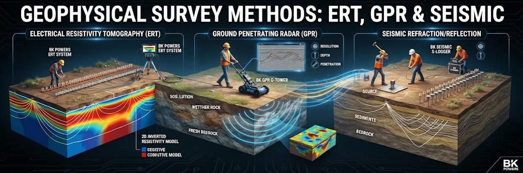
Geophysical Survey Methods: ERT, GPR & Seismic
TIPS:This authoritative technical handbook delivers a systematic overview of geophysical methods for non-destructive subsurface investigation across civil infrastructure, mineral exploration and environmental projects worldwide. It explains core physical principles of geophysical methods, with detailed analysis of electrical resistivity tomography deployment workflows and electrical resistivity tomography performance benchmarks for field engineering practice and project optimization.
Ⅰ. Core Concepts and Classification of Geophysical Methods
1. Definition and Scientific Basis
Geophysical methods are non-destructive techniques that infer subsurface structures by measuring physical fields at the surface. These methods detect contrasts in physical properties between different rock, soil and fluid media. Inversion algorithms convert surface observation data into 2D or 3D distributions of subsurface physical properties. Spatial resolution decreases exponentially with increasing investigation depth across all geophysical techniques.
2. Categorization Framework
Geophysical methods fall into two primary categories based on their field source. Passive methods measure naturally occurring geophysical fields without artificial energy input. Active methods generate controlled artificial fields and measure the subsurface response.
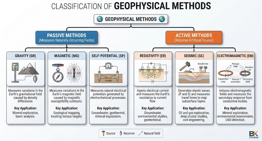
| Category | Physical Field | Representative Techniques | Primary Application Scenarios |
|---|---|---|---|
| Passive Methods | Gravity field | Gravity survey | Regional geological mapping, ore body density contrast detection |
| Passive Methods | Geomagnetic field | Magnetic survey | Mineral exploration, fault mapping, archaeological prospection |
| Passive Methods | Natural electric field | Spontaneous Potential (SP) | Groundwater flow mapping, seepage detection |
| Active Methods | DC electric field | Resistivity, ERT, VES, IP | Near-surface engineering, hydrogeology, mineral exploration |
| Active Methods | Electromagnetic field | GPR, TEM, FDEM | Utility detection, deep aquifer mapping, contaminant monitoring |
| Active Methods | Elastic wave field | Seismic refraction, reflection, MASW | Deep geological structure, geotechnical site characterization |
Ⅱ. Technical Deep Dive into Mainstream Methods
1. Resistivity-Based Electrical Methods
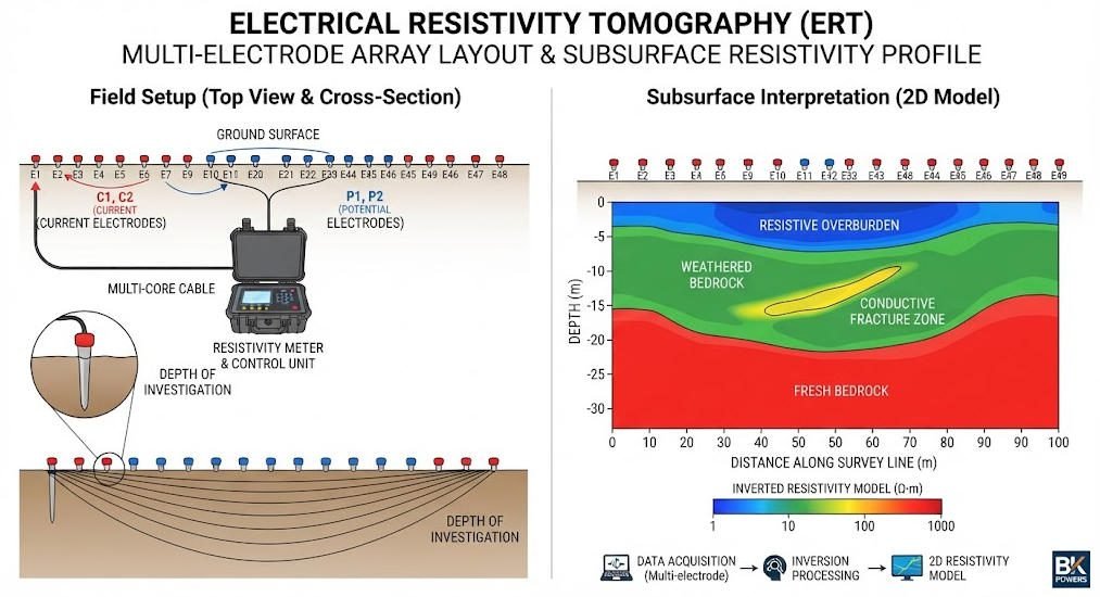
Resistivity methods form the most widely used category of near-surface geophysical techniques. They operate on the principle that different subsurface materials exhibit characteristic electrical resistivity values. Dry rock and clean gravel show high resistivity, while clay, saturated soil and mineralized zones show low resistivity.
High-Density Resistivity (HDR)
High-Density Resistivity uses automated multi-electrode arrays with 60 to 120 channels. It generates continuous 2D and 3D resistivity profiles along survey lines. This method achieves data acquisition speeds 5 times faster than traditional DC resistivity methods. Digital filtering technology delivers 80dB signal-to-noise ratio even in urban environments with strong electromagnetic interference. It can identify karst conduits with diameters smaller than 5 meters in carbonate terrains.
Electrical Resistivity Tomography (ERT)
ERT is an advanced resistivity imaging technique that produces high-resolution 2D and 3D subsurface models. Modern ERT systems use automated electrode switching and multi-channel data acquisition. ConvResNet AI inversion algorithms reduce 3D modeling time from 24 hours to 1.8 hours, dramatically improving project efficiency. High-voltage 1000V systems extend effective penetration depth to 300 meters in resistive geological formations. Effective investigation depth equals approximately one-fifth to one-third of the total electrode array spread.
Vertical Electrical Sounding (VES)
VES is a traditional 1D resistivity technique that measures resistivity variation with depth at a single point. It uses expanding electrode arrays to probe progressively deeper subsurface layers. VES offers lower cost and simpler logistics compared to ERT, but provides no lateral resolution. It remains the preferred method for preliminary reconnaissance and simple layered aquifer characterization.
Induced Polarization (IP)
Induced Polarization measures the transient voltage decay after the injected current is switched off. It detects chargeability differences between subsurface materials, particularly sulfide mineralization. IP is widely used in mineral exploration to identify disseminated sulfide ore bodies that may not show strong resistivity contrasts. High-power IP systems can achieve investigation depths exceeding 500 meters in suitable geological conditions.
| Method | Detection Depth | Lateral Resolution | Channel Count | Core Advantage | Typical Application |
|---|---|---|---|---|---|
| HDR | 10–500 m | 1–5 m | 60–120 | Fast acquisition, high SNR | Karst detection, engineering site survey |
| ERT | 5–300 m | 0.5–3 m | 48–120 | 2D/3D imaging, AI inversion | Dam monitoring, 3D ore body modeling |
| VES | 20–800 m | N/A (1D) | 4 | Low cost, simple logistics | Regional aquifer reconnaissance, bedrock depth |
| IP | 50–600 m | 2–10 m | 24–96 | Sulfide detection capability | Mineral exploration, disseminated ore targeting |
2. Electromagnetic and Radar Methods
Electromagnetic methods use time-varying magnetic fields to induce eddy currents in the subsurface. They measure the secondary electromagnetic response to infer subsurface conductivity distribution. Unlike resistivity methods, most EM techniques do not require direct galvanic contact with the ground.
Ground Penetrating Radar (GPR)
GPR transmits high-frequency electromagnetic pulses into the ground and records reflected signals from dielectric interfaces. Frequency selection directly controls the trade-off between penetration depth and spatial resolution. 100MHz antennas deliver approximately 10 meters of detection depth with 0.3 meter resolution, ideal for municipal pipeline detection. 2.6GHz antennas achieve 2 centimeter resolution at 0.5 meter depth, used for concrete defect inspection and pavement quality assessment. Multi-frequency GPR surveys identified 22,370 cubic meters of karst cavities in Wuhan urban area, demonstrating strong engineering value.
Transient Electromagnetic Method (TEM)
TEM uses pulsed magnetic fields generated by a transmitter loop on the surface. It measures the decay of the secondary magnetic field after the primary field is switched off. A 40×40 meter transmitter loop typically achieves 200–250 meters of investigation depth. Larger loops and higher transmitter power can extend depth beyond 800 meters. TEM has a shallow blind zone of 10–20 meters due to transmitter turn-off effects. It excels at mapping conductive targets such as brine aquifers and graphite mineralization.
Frequency Domain Electromagnetic (FDEM)
FDEM operates at fixed frequencies to measure apparent conductivity of the subsurface. It offers very fast data acquisition and is commonly used for rapid regional mapping. Typical investigation depths range from 5 to 60 meters depending on frequency and coil spacing. FDEM is widely applied in environmental site assessment and soil salinity mapping.
3. Seismic Survey Methods
Seismic methods generate elastic waves in the ground and record their propagation characteristics. Wave velocity and impedance contrasts between geological formations produce reflections and refractions. Inversion of travel time and amplitude data produces subsurface velocity and density models.
Seismic Refraction
Refraction seismic methods measure waves that bend along interfaces between layers with different velocities. They are primarily used to determine bedrock depth and map layer boundaries. Refraction surveys work best where seismic velocity increases with depth, which is common in most near-surface settings. Typical investigation depths range from 5 to 200 meters for engineering-scale surveys.
Seismic Reflection
Reflection seismic records waves reflected back from impedance contrasts between geological layers. It provides detailed images of subsurface stratigraphy, faults and geological structures. Reflection methods dominate hydrocarbon exploration and deep mineral exploration. Engineering-scale reflection surveys can achieve resolution of 1–2 meters at depths up to 500 meters.
Multichannel Analysis of Surface Waves (MASW)
MASW analyzes the dispersion characteristics of Rayleigh surface waves to invert shear wave velocity profiles. Shear wave velocity directly correlates with soil stiffness and geotechnical engineering properties. This method effectively evaluates soil liquefaction potential and foundation bearing capacity. Typical investigation depth is approximately 50 meters for standard engineering surveys.
Microseismic Monitoring
Microseismic monitoring detects and locates tiny seismic events associated with subsurface deformation. It achieves positioning accuracy of ±3 meters for fluid injection and storage projects. The technology is widely used for CO₂ storage leakage warning and rock mass stability monitoring in mines.
Ⅲ. Cross-Method Performance Comparison and Selection Guide
1. Comparative Performance Matrix
The following matrix provides a side-by-side comparison of all mainstream geophysical methods across key performance parameters. This reference helps engineers quickly narrow down method options based on project requirements.
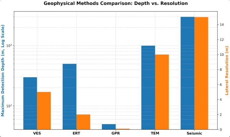
| Method | Max Effective Depth | Lateral Resolution | Ground Contact Required | Urban Noise Tolerance | Relative Cost | Primary Strength |
|---|---|---|---|---|---|---|
| GPR | 30 m | 0.02–0.3 m | No | Medium | Low | Ultra-high shallow resolution |
| ERT | 300 m | 0.5–3 m | Yes (electrodes) | Good | Medium | 2D/3D resistivity imaging |
| VES | 800 m | N/A | Yes | Good | Very Low | 1D depth sounding, low cost |
| TEM | 800+ m | 5–20 m | No | Poor | Medium-High | Deep conductive target detection |
| Seismic Refraction | 200 m | 2–5 m | Yes (geophones) | Poor | Medium | Bedrock and layer boundary mapping |
| Seismic Reflection | 500+ m | 1–3 m | Yes | Poor | High | Detailed stratigraphic imaging |
| Magnetic | Unlimited (depth of source) | 5–50 m | No | Excellent | Very Low | Regional reconnaissance, fast coverage |
| Gravity | Unlimited | 10–100 m | No | Excellent | Low | Density contrast detection |
2. Method Selection Framework
Selecting the optimal geophysical method requires balancing project objectives, geological conditions, logistics and budget. No single method delivers optimal performance across all scenarios. Most successful projects combine multiple complementary methods to reduce interpretation ambiguity.
For shallow urban engineering projects with targets less than 10 meters deep, GPR is usually the first choice. It provides centimeter-scale resolution and requires no ground disturbance, making it ideal for road and utility surveys. In areas with conductive clay soils that attenuate GPR signals, ERT serves as an effective alternative.
For mineral exploration projects targeting depths of 100–500 meters, IP and TEM methods deliver the best performance. IP excels at identifying sulfide mineralization, while TEM provides deep penetration in conductive terrains. Seismic reflection surveys add structural control for deeper ore bodies and geological mapping.
For geotechnical site characterization, seismic refraction and MASW provide critical geomechanical parameters. Shear wave velocity from MASW directly supports foundation design and seismic hazard assessment. ERT complements these methods by providing groundwater and lithology information.
For environmental monitoring projects, time-lapse ERT is the gold standard for tracking plume migration. TEM and FDEM provide rapid screening of large contaminated sites. GPR monitors shallow landfill boundaries and underground storage tank integrity.
Ⅳ. Industrial Applications and Engineering Practice
1. Mineral Exploration Applications
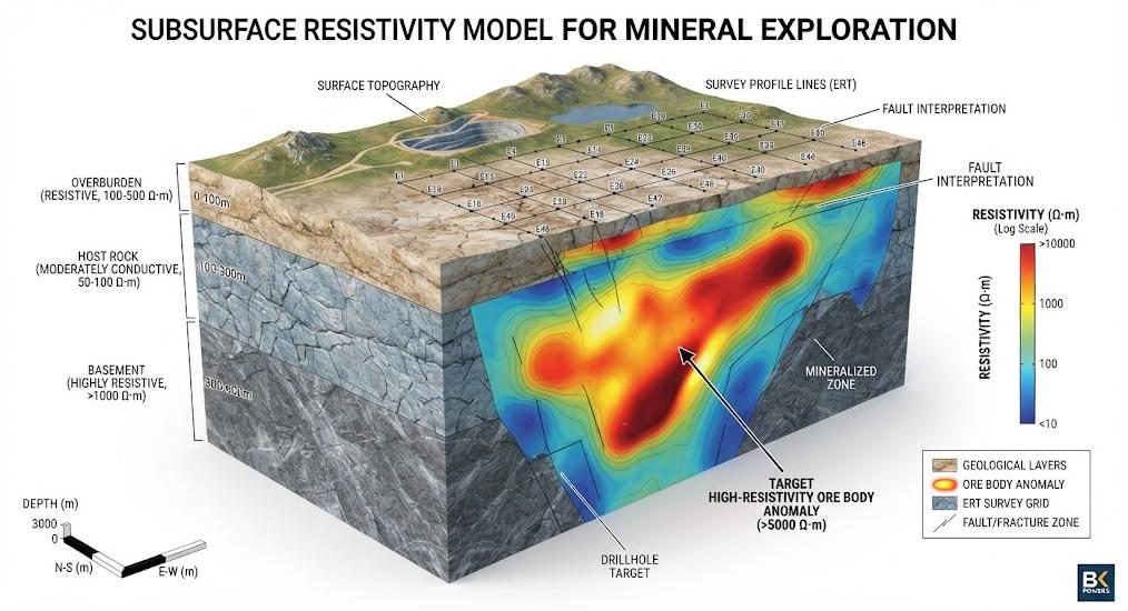
Geophysical methods reduce exploration risk and drilling costs by identifying subsurface anomalies before drilling. Integrated geophysical surveys typically reduce overall exploration costs by 30–40% compared to drilling-only programs.
In Guangdong Pb-Zn mines, 3D ERT surveys successfully differentiated silicified ore zones with resistivity greater than 2000 Ω·m. The survey achieved interpretation error of less than 8% compared to subsequent drilling results. This approach allowed engineers to target drill holes more accurately and reduce total meterage required.
In lithium brine exploration, TEM methods map conductive brine aquifers beneath thick desert alluvium. Combined with VES for calibration, TEM surveys provide cost-effective regional mapping of aquifer geometry. This approach has become standard practice in Andean lithium exploration programs.
2. Geotechnical Engineering Applications
Geophysical methods play a critical role in all phases of civil infrastructure projects. They provide subsurface information between boreholes with minimal ground disturbance.
In subway tunnel construction, the combination of GPR and MASW detects boulder clusters in shield tunnel zones. Early identification of these hazards allows ground improvement before tunneling, reducing construction risk and delays. Time-lapse ERT also monitors ground settlement and groundwater changes during tunnel advancement.
For dam safety monitoring, time-lapse ERT tracks embankment core saturation changes with ±2% accuracy. Regular surveys detect seepage pathways and internal erosion before they develop into critical failures. This technology extends dam service life and reduces maintenance costs over the asset lifecycle.
In highway engineering, GPR surveys assess pavement thickness and detect underlying voids that cause road collapse. High-speed GPR systems mounted on vehicles can survey hundreds of kilometers per day. This enables regular network-level pavement condition assessment at a fraction of the cost of coring.
3. Environmental and Hydrogeological Applications
Geophysical methods support environmental protection and water resource management through non-invasive subsurface characterization. They enable large-scale monitoring without drilling or soil disturbance.
For contaminant site assessment, the combination of TEM and ERT maps volatile organic compound (VOC) plumes. Conductive plumes produce distinct resistivity anomalies that can be tracked over time. This approach guides remediation design and monitors treatment effectiveness without invasive sampling.
In permafrost regions, UAV infrared surveys combined with ERT monitor permafrost thaw progression. Thawing permafrost reduces ground stability and releases greenhouse gases. Geophysical monitoring provides early warning of thaw hazards for infrastructure built on permafrost.
In hydrogeology, integrated ERT and VES surveys map aquifer geometry and characterize groundwater quality. Resistivity data distinguishes between fresh and saline groundwater in coastal aquifers. This information supports sustainable groundwater management and saltwater intrusion monitoring.
Ⅴ. Equipment Innovation and Technological Breakthroughs
1. Core Equipment Product Lines
Modern geophysical instrumentation integrates advanced electronics, wireless communication and AI processing. The following product lines represent the current state of the art in exploration geophysics.
| Product Line | Key Technology Innovations | Primary Application Scenarios |
|---|---|---|
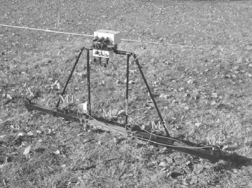
| GIM Series Resistivity Systems | 120-channel AI switching, high-voltage output | 3D metal ore modeling, dam safety monitoring |
| Geological Radar (GPR) Series | Multi-frequency synchronization, high-speed acquisition | Urban road collapse warning, utility detection |
| Seismic Nodal Systems | 500-node wireless network, autonomous recording | Site seismic risk assessment, microseismic monitoring |
| DJF Series High-Power IP Systems | 5kW/10kW digital DC output, full-waveform acquisition | Deep mineral exploration, brine aquifer mapping |
2. Key Technology Trends
AI-powered inversion represents the most transformative technology trend in recent years. Deep learning models trained on geological data produce more accurate subsurface models in a fraction of the time. This technology makes 3D surveys practical for projects that previously could only afford 2D profiles.
Wireless and autonomous operation reduces field crew requirements and logistics costs. Modern seismic nodes and EM sensors operate independently with built-in GPS and data storage. This enables large-scale surveys with minimal cabling and faster deployment.
Multi-method integration platforms allow a single instrument to perform multiple survey types. Unified data processing workflows simplify interpretation and reduce training requirements for field teams. This integrated approach improves data consistency and reduces overall project costs.
High-power digital transmitters extend investigation depth and improve signal quality. Modern systems use precise digital timing and advanced noise cancellation to work in challenging environments. This expands the range of geological conditions where geophysical methods deliver reliable results.
Ⅵ. Field Deployment and Quality Control
1. Standard Survey Workflow
Successful geophysical surveys follow a structured workflow from planning through final interpretation. Skipping steps or cutting corners on quality control leads to unreliable data and incorrect interpretations.
First, project design defines survey objectives, target depth and required resolution. Engineers select appropriate methods and design survey layouts based on local geological conditions. Pilot tests confirm method suitability before full-scale deployment.
Second, field deployment involves equipment setup and station layout. Electrodes, geophones or antennas are placed at precise locations according to the survey design. Equipment calibration and test measurements verify system performance before data acquisition begins.
Third, data acquisition follows standardized operating procedures. Field technicians monitor data quality in real time and repeat measurements that fail quality thresholds. Environmental conditions and any interference sources are documented for later processing reference.
Fourth, data processing applies filtering, correction and inversion algorithms to raw field data. Processing parameters are selected based on geological conditions and survey objectives. Quality checks at multiple processing stages ensure data integrity.
Finally, geological interpretation integrates geophysical results with available borehole and geological data. Experienced geophysicists produce final subsurface models and interpretation reports. All interpretations include uncertainty estimates and recommendations for follow-up work.
2. Quality Assurance Protocols
Rigorous quality control is essential for reliable geophysical survey results. The following protocols ensure data accuracy and reproducibility.
Repeat measurements at 5–10% of stations provide quantitative assessment of data repeatability. Differences exceeding predefined thresholds trigger investigation and remeasurement. This practice identifies equipment drift and operator error before they compromise the entire dataset.
Diurnal correction applies to magnetic and gravity surveys to account for natural temporal field variations. Base station measurements recorded throughout the survey provide reference data for correction. This removes daily variation signals that would otherwise mask subsurface anomalies.
Noise suppression techniques include digital filtering, stacking and spatial averaging. Modern systems use adaptive filtering algorithms that automatically adjust to local noise conditions. This maintains data quality even in urban and industrial environments with high electromagnetic noise.
Cross-validation with borehole data calibrates geophysical interpretations and reduces uncertainty. Where drilling data is available, inversion parameters are adjusted to match known geological conditions. This calibration improves the accuracy of interpretations in unsurveyed areas.
Related Articles
| Title | Core Content | URL |
|---|---|---|
| What Is Electrical Resistivity Tomography (ERT)? | ERT fundamentals, electrode arrays, 2D/3D inversion and applications | https://geotechcn.net/service/what-is-electrical-resistivity-tomography/ |
| Electrical Resistivity Tomography: A Complete Technical Guide | ERT principles, Ohm’s law, electrode configuration and inversion | https://geotechcn.net/service/electrical-resistivity-tomography-a-complete-technical-guide/ |
| What Is an ERT Instrument? | ERT equipment, high-density resistivity and DC sounding | https://geotechcn.net/service/ert-instruments/ |
| Proton Magnetometer Technology | Proton precession magnetometer principles and applications | https://geotechcn.net/service/proton-magnetometer-technology/ |
| GER Series Ground Penetrating Radar | GPR equipment and engineering applications | https://geotechcn.net/products/geological-radar/ger-series-ground-penetrating-radar/ |
| Advanced Applications | Integrated electrical, magnetic, seismic and radar exploration applications | https://geotechcn.net/service/advanced-applications/ |
| GIM-10 Multi-channel Resistivity & IP Meter | Resistivity and IP acquisition equipment | https://geotechcn.net/company-news/gim-10-multi-channel-intelligent-resistivity-ip-meter/ |
Reference Sources
| Title | Core Content | URL |
|---|---|---|
| US EPA — Geophysical Methods | Classification and principles of surface, borehole and waterborne geophysics | http://www.epa.gov/environmental-geophysics/geophysical-methods |
| US EPA — Surface Geophysical Methods | Method selection, target properties, depth of investigation and integrated surveys | http://www.epa.gov/environmental-geophysics/surface-geophysical-methods |
| US EPA — Electrical Methods | Resistivity, IP, SP and electrical-property fundamentals | http://www.epa.gov/environmental-geophysics/electrical-methods |
| US EPA — Ground Penetrating Radar | GPR electromagnetic principles and subsurface reflection | http://www.epa.gov/environmental-geophysics/ground-penetrating-radar-gpr |
| USGS — Geophysical Methods | Surface and borehole geophysical methods used in groundwater investigations | http://water.usgs.gov/ogw/bgas/methods.html |
FAQ
Q1: What is the core difference between passive and active geophysical methods?
Passive methods measure natural geophysical fields, while active methods deploy artificially induced signals. Passive techniques use ambient gravity or magnetism with no energy input. Active methods inject current or seismic waves for controlled probing. Passive methods suit regional reconnaissance; active methods serve high-resolution engineering projects.
Q2: How deep can Electrical Resistivity Tomography (ERT) effectively survey?
Standard ERT systems achieve effective depths of 10–300 meters depending on electrode spacing. Depth penetration equals roughly one-fifth to one-third of total array spread, with wider spacing trading resolution for depth. ERT works best for dam monitoring and shallow ore body mapping projects.
Q3: What factors should I consider when choosing between GPR and ERT?
Prioritize GPR for shallow, high-resolution targets and ERT for deeper, lower-conductivity settings. GPR delivers centimeter-scale resolution down to 30 meters but struggles in clay-rich soils. Select GPR for utility detection; choose ERT for groundwater and geotechnical site characterization.
Q4: Can geophysical methods accurately detect underground cavities?
Yes, integrated geophysical methods reliably detect subsurface cavities with meter-scale accuracy. GPR identifies shallow voids through dielectric contrast, while ERT maps resistivity anomalies from air-filled cavities. This combination supports urban road collapse risk assessment and karst hazard mapping.
Q5: How does AI inversion improve geophysical data processing?
AI inversion accelerates 3D subsurface modeling and improves interpretation accuracy compared to traditional algorithms. Deep learning models like ConvResNet reduce ERT 3D inversion time from 24 hours to under 2 hours. This technology cuts project timelines for large-scale mineral and infrastructure surveys.