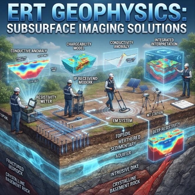
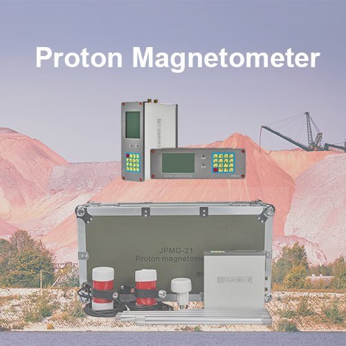
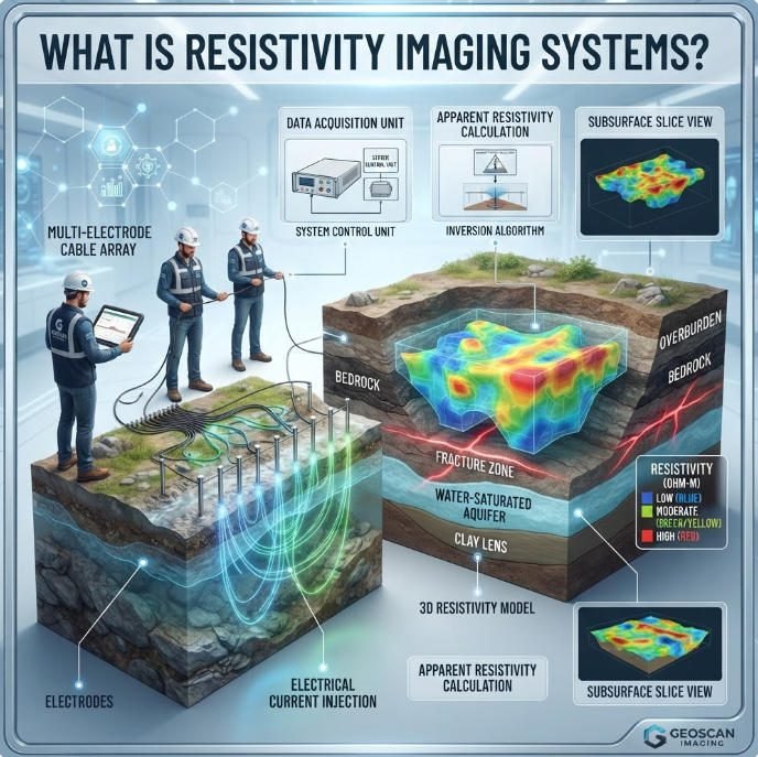
Welcome to Geotech!


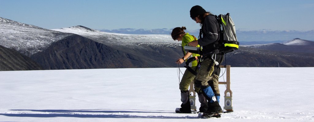
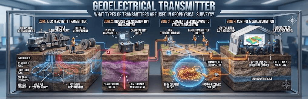
Geoelectrical Transmitter:What types of transmitters are used in geophysical surveys?
Overview:A Geoelectrical Transmitter injects controlled electrical energy into the ground for subsurface investigation. Selecting suitable Geotechnical Equipment requires an understanding of output limits, electrode contact, geological conditions, and receiver compatibility. This guide explains transmitter principles, system architectures, field workflows, and practical selection criteria for resistivity and induced polarization surveys.
Ⅰ. What Is a Geoelectrical Transmitter?

A Geoelectrical Transmitter is an electrical source that injects controlled current or voltage into the ground for geophysical investigation. It supports methods such as direct-current resistivity and induced polarization.
The transmitter forms part of a measurement system. Depending on the survey, the system may include a receiver, electrodes, cables, switching units, synchronization controls, and data processing software.
Engineers use geoelectrical transmitters to create an electrical field in the subsurface. They then measure the resulting electrical response to investigate changes in ground resistivity and polarization properties.
The term geoelectrical transmitter describes a functional equipment category. It does not define one universal waveform, power level, or measurement method.
Ⅱ. How Does a Geoelectrical Transmitter Work?
1. Current Injection into the Ground
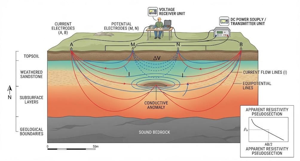
A geoelectrical transmitter applies an electrical potential between current electrodes. These electrodes are commonly labeled A and B.
The resulting current flows through the ground. Its distribution depends on electrode geometry, subsurface resistivity, contact conditions, and the electrical properties of the surrounding materials.
The transmitter must operate within its voltage, current, and power limits. Actual output depends on the electrical load formed by the ground and electrode contacts.
For a simplified resistive load, Ohm’s law gives:
V=IR
Where:
- V is voltage in volts.
- I is current in amperes.
- R is resistance in ohms.
This relationship explains why high-resistance ground can limit current. The transmitter may reach its maximum voltage before reaching its rated current.
2. Electrical Potential Measurement
A geoelectrical survey commonly uses a second pair of electrodes to measure the resulting potential difference. These electrodes are often labeled M and N.
The receiver measures the voltage between the potential electrodes. The measured voltage depends on the injected current, electrode arrangement, and subsurface electrical properties.
By repeating measurements with different electrode positions or spacings, engineers collect information about the spatial distribution of electrical properties.
3. Resistivity and Induced Polarization
Resistivity surveys estimate the electrical resistivity of subsurface materials from current and voltage measurements.
Induced polarization (IP) surveys measure an additional electrical response associated with charge accumulation and relaxation in geological materials. After the transmitter switches off the current, the voltage may decay rather than immediately returning to zero.
The US EPA explains that this response relates to the electrical properties of mineral–fluid and grain–fluid interfaces. IP
4. Why the Measurement Sequence Matters
A transmitter must deliver the excitation sequence required by the selected survey method.
A typical time-domain resistivity/IP sequence includes:
- Apply a controlled current pulse.
- Maintain the pulse for the programmed interval.
- Switch off the current.
- Measure the voltage response.
- Record the data and repeat the sequence as required.
- Process the measurements into resistivity and polarization parameters.
The exact sequence depends on the instrument, receiver, measurement method, and survey design.
Ⅲ. Main Types of Geoelectrical Transmitters
1. Resistivity Transmitters
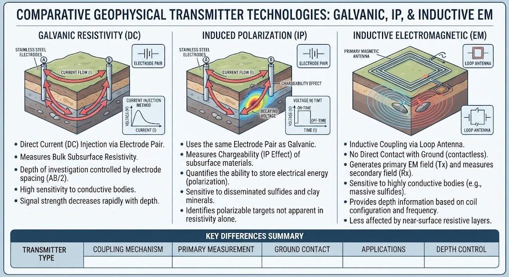
A resistivity transmitter injects electrical current into the ground for DC resistivity measurements.
The receiver measures the resulting potential difference. Engineers combine current, voltage, and electrode geometry to calculate apparent resistivity.
These systems can support vertical electrical sounding, electrical profiling, and electrical resistivity tomography. The actual capability depends on the equipment configuration and acquisition software.
2. IP Transmitters
An IP transmitter supports measurements of induced polarization. It may deliver programmed current pulses for time-domain IP or support other excitation patterns where the system is designed for them.
In time-domain IP, the receiver records voltage decay after the current pulse ends. In frequency-domain IP, the system measures electrical responses at different frequencies.
The US EPA describes time-domain, frequency-domain, and spectral IP as related approaches that examine polarization through different measurement strategies.
3. Electromagnetic Transmitters
An electromagnetic transmitter generates a time-varying electrical current in a coil, loop, or other transmitting structure.
The changing current creates a primary magnetic field. That field induces electrical currents in conductive subsurface materials. A receiver measures the resulting electromagnetic response.
This differs from galvanic geoelectrical transmission, which injects current into the ground through electrodes.
The US EPA explains that transient electromagnetic methods measure the decay of a secondary response after the transmitted signal is switched off.
4. Comparing Transmitter Types
| Transmitter Type | Coupling Method | Typical Measurement | Typical Application |
|---|---|---|---|
| DC resistivity transmitter | Direct electrical contact through electrodes | Current and potential difference | Resistivity profiling, VES, ERT |
| IP transmitter | Direct electrical contact through electrodes | Resistivity and polarization response | Mineral exploration and other IP surveys |
| Frequency-domain IP source | Direct electrical contact through electrodes | Frequency-dependent electrical response | Spectral or frequency-domain IP |
| TEM transmitter | Electromagnetic induction through a loop or coil | Transient electromagnetic response | Conductivity mapping and deeper subsurface investigation |
| FDEM transmitter | Electromagnetic induction | Amplitude and phase response | Conductivity mapping and rapid surveys |
These systems are not interchangeable. The appropriate transmitter depends on the physical method and survey objective.
Ⅳ. Key Components of a Geoelectrical Survey System
1. Transmitter Unit
The transmitter converts its available power source into controlled electrical output.
Depending on its design, it may include:
- Output regulation and pulse control.
- Current or voltage monitoring.
- Timing and synchronization functions.
- Status indicators and fault protection.
- Interfaces for control or data logging.
The available functions differ among instruments. Engineers should verify them in the manufacturer’s documentation.
2. Receiver Unit
The receiver measures electrical potential differences or other signals specified by the survey method.
For resistivity and IP surveys, it records voltage responses between potential electrodes. Depending on the system, it may support multiple channels, automatic stacking, waveform recording, and field quality-control functions.
Input range, noise performance, timing compatibility, and channel configuration influence data quality.
3. Electrodes and Cables
Current electrodes inject electrical energy into the ground. Potential electrodes measure the electrical response.
Electrode contact conditions affect current delivery and measurement stability. Dry, rocky, frozen, or highly resistive surfaces may require special installation procedures.
Cable insulation, connectors, conductor condition, and routing also influence reliability. Damaged cables or poor connections can cause unstable readings and create safety hazards.
4. Switching and Synchronization Units
Multi-electrode systems may use switching units to connect electrodes according to a programmed sequence.
The switching system must be compatible with the transmitter, receiver, electrode layout, and acquisition software.
Synchronization ensures that the receiver measures the correct part of the excitation sequence. Timing errors can compromise data quality, especially in IP measurements.
Ⅴ. Understanding Geoelectrical Transmitter Specifications

A useful specification review separates rated capability from actual field performance.
1. Output Voltage, Current, and Power
Voltage describes the electrical potential available to drive current through the ground. Current describes the rate of electrical charge flow. Power describes the rate of energy transfer.
For a DC output:
P=VI
This equation gives electrical power when voltage and current refer to the same operating point.
Maximum voltage and maximum current may not be available simultaneously. The output may be limited by rated power, thermal protection, load characteristics, or the selected operating mode.
2. Load Resistance and Current Delivery
The transmitter’s practical output depends on the total electrical load. The load includes the ground path, electrode contacts, and other elements of the current circuit.
For an idealized resistive load:
I=RV
If the required voltage exceeds the transmitter’s output limit, the actual current will be lower than the desired value.
A high power rating alone does not guarantee strong current delivery in every geological setting.
3. Current Regulation and Voltage Regulation
Some transmitters regulate output current. Others regulate voltage or use adaptive control strategies.
| Control Mode | Main Characteristic | Potential Benefit | Engineering Consideration |
|---|---|---|---|
| Current-regulated | Controls current within operating limits | Helps maintain a current target when sufficient voltage headroom exists | Current may decrease at the voltage limit |
| Voltage-regulated | Controls output voltage within operating limits | Provides a defined voltage target | Current varies with load resistance |
| Adaptive control | Adjusts output according to control logic | May simplify operation under changing loads | Verify control behavior and limits |
These modes describe control behavior. They do not establish a universal performance ranking.
4. Pulse Width and Duty Cycle
Pulse width defines how long a transmitter applies a current pulse.
Duty cycle describes the proportion of a defined cycle during which the system remains energized. The exact definition may vary by instrument and operating mode.
Pulse timing must match the receiver’s acquisition windows. Engineers should confirm the supported pulse sequence and timing resolution before combining instruments.
5. Environmental and Protection Specifications
Protection features may include overcurrent protection, overtemperature protection, output fault detection, and short-circuit protection.
Environmental suitability depends on operating temperature, moisture exposure, dust, transport conditions, and enclosure design.
Do not assume that a transmitter is suitable for wet or hazardous environments without checking its documented rating and operating instructions.
Ⅵ. How to Select Geoelectrical Transmitter Equipment
1. Define the Survey Objective
Start with the geological question the survey must answer.
Examples include:
- Mapping electrical resistivity contrasts.
- Investigating potential mineralized zones.
- Characterizing groundwater-related structures.
- Identifying subsurface variability in engineering projects.
- Supporting environmental site characterization.
The objective determines the method, electrode geometry, measurement sequence, and data quality requirements.
2. Evaluate Geological and Electrical Conditions
Ground conditions influence the transmitter’s ability to deliver current.
Important factors include:
- Expected resistivity range.
- Surface moisture and soil type.
- Rock exposure and electrode contact.
- Groundwater and pore-fluid characteristics.
- Geological layering and structural complexity.
- Electrical noise and nearby infrastructure.
Depending on geological conditions, the same transmitter may deliver different current levels at different sites.
3. Match Output Capability to the Survey Design
Do not select a transmitter solely by its maximum power rating.
Estimate the expected load and required current for the planned electrode geometry. Then confirm that the transmitter can operate within its documented voltage, current, and power limits.
The design should also account for pulse timing, receiver input range, measurement windows, and the desired data quality.
4. Verify Receiver and System Compatibility
The transmitter and receiver must support compatible electrical and timing configurations.
Confirm the following before procurement:
- Supported waveform and polarity.
- Voltage and current operating ranges.
- Timing and synchronization interfaces.
- Receiver input range and acquisition windows.
- Electrode and cable configuration.
- Switching unit compatibility.
- Data format and processing workflow.
Use official technical documentation or a verified system configuration to establish compatibility.
5. Consider Field Deployment
Field productivity depends on more than output power.
Evaluate equipment weight, power supply, transport, cable deployment, electrode installation, environmental conditions, and crew training.
A compact system may simplify transport. A modular system may provide greater configuration flexibility. The preferred setup depends on access, survey scale, and measurement objectives.
Ⅶ. Engineering Workflow: From Planning to Interpretation
1. Site Assessment and Survey Design
Review the geological setting, project objectives, existing data, and access constraints.
Select the method and survey geometry based on the target’s expected dimensions, depth, and electrical contrast.
Plan electrode positions, current and potential configurations, acquisition sequences, and quality-control checks before mobilization.
2. Equipment Inspection
Before connecting the system:
- Inspect the transmitter, receiver, cables, connectors, and electrodes.
- Check the power source and instrument status.
- Confirm the approved system configuration.
- Verify timing and communication settings.
- Review the site-specific safety plan.
Follow the manufacturer’s instructions. Do not modify high-voltage connections while the system is energized.
3. Electrode Installation and Contact Checks
Install electrodes according to the survey layout. Ensure that connections are secure and contact conditions are suitable for the measurement.
If contact is poor, follow the approved field procedure to improve it. Record unusual conditions that may affect current delivery or data quality.
Do not assume that a single contact-resistance threshold applies to every instrument or survey.
4. Test Transmission and Data Acquisition
Run a controlled test using the approved procedure.
Check whether the transmitter delivers the expected output within its operating limits. Confirm that the receiver records the intended measurement sequence.
Review current, voltage, noise, and contact indicators where available. Resolve abnormal behavior before starting full production measurements.
5. Production Measurement
Execute the planned measurement sequence.
Monitor instrument status, electrode contact, current stability, and data quality throughout the survey. Repeat or adjust measurements when the acquisition protocol identifies unreliable readings.
Document changes in field conditions and deviations from the original survey design.
6. Data Processing and Interpretation
For a simplified DC resistivity measurement:
ρa=KIΔV
Where:
- ρa is apparent resistivity.
- K is the geometric factor for the electrode configuration.
- ΔV is the measured potential difference.
- I is the injected current.
The equation assumes a compatible measurement convention and electrode geometry. Actual processing must follow the survey’s array definition and instrument conventions.
IP processing may include stacking, decay-window analysis, chargeability calculation, filtering, and quality assessment. The selected method depends on the waveform, receiver, and acquisition protocol.
7. Inversion and Geological Interpretation
Apparent resistivity values are not direct images of geological boundaries.
Inversion estimates a subsurface model that explains the observed data under specified assumptions. Model resolution depends on survey geometry, noise, data coverage, and the inversion method.
Interpretation should consider geological knowledge, topography, borehole information, and independent observations where available.
Ⅷ. Quality Assurance and Troubleshooting
1. Common Field Problems
| Symptom | Possible Causes | Recommended Checks |
|---|---|---|
| Low or unstable current | High contact resistance, resistive ground, cable faults, output limits | Inspect electrodes and cables; check load and output status |
| Weak IP response | Geological properties, poor signal-to-noise ratio, timing mismatch | Review acquisition settings, contact, noise, and measurement sequence |
| Unstable voltage readings | Electrical interference, loose connections, poor electrode contact | Inspect connections and survey environment |
| Inconsistent repeat measurements | Changing contact, environmental variation, timing or configuration changes | Repeat under controlled conditions and document changes |
| Unexpected output shutdown | Protection activation, overload, temperature, power supply issue | Follow the manual’s fault procedure before restarting |
These are diagnostic possibilities, not definitive fault diagnoses. The correct action depends on instrument design and site conditions.
2. Data Quality Checks
A quality-control plan may include:
- Reviewing current and voltage stability.
- Checking repeated measurements for consistency.
- Identifying outliers and abnormal decay curves.
- Recording electrode contact and field conditions.
- Confirming the correct timing and configuration.
- Preserving raw data and acquisition metadata.
Quality control should be integrated into field acquisition rather than postponed until the survey ends.
Ⅸ. Safety Considerations for Geoelectrical Transmitters
1. Electrical Hazards
Geoelectrical transmitters may deliver hazardous voltage and current. Risk depends on the equipment, operating configuration, ground conditions, and field environment.
High-voltage DC equipment requires controlled access, clear communication, and trained personnel. The operating team must follow the manufacturer’s safety procedures and the project’s electrical safety plan.
2. Safe Field Practices
- Inspect cables, connectors, and insulation before use.
- Establish a controlled work area around electrodes and energized circuits.
- Keep personnel away from exposed conductors during transmission.
- Follow the approved shutdown and discharge procedure.
- Verify the system is de-energized before handling connections.
- Stop work if equipment behavior or site conditions become unsafe.
A shutdown command alone should not be treated as proof that all hazardous energy has been removed. Follow the manufacturer’s verification procedure.
3. Site-Specific Risk Assessment
Safety requirements may change with weather, soil moisture, terrain, nearby utilities, and public access.
The project team should identify site hazards before energizing the system. Where required, coordinate with utility owners and site managers.
Ⅹ. Applications of Geoelectrical Transmitters
1. Mineral Exploration
Resistivity and IP surveys can help investigate electrical contrasts associated with mineralized zones and surrounding geological materials.
IP responses depend on mineralogy, grain size, alteration, pore fluids, and geological setting. An electrical anomaly does not prove the presence of economic mineralization.
2. Groundwater Investigation
Geoelectrical surveys can help characterize subsurface contrasts associated with geological structures and groundwater-related conditions.
Interpretation must account for lithology, pore-fluid salinity, saturation, clay content, and other factors. Geophysical results should be integrated with hydrogeological evidence.
3. Engineering Geophysics
Electrical methods may support investigations of subsurface variability, weathered zones, fractures, and other features relevant to engineering projects.
The method’s suitability depends on the target, site geometry, ground conditions, and required resolution.
4. Environmental Site Investigation
Resistivity and IP can contribute to environmental site characterization. Their usefulness depends on the electrical contrast between the target and surrounding materials.
Geophysical measurements do not directly identify chemical contaminants. Sampling and laboratory analysis may be needed to confirm environmental conditions.
Ⅺ. Geotechnical Equipment and Geotechnical Instrument: Key Differences
1. Geotechnical Equipment
Geotechnical Equipment is a broad term for tools and systems used in subsurface investigation, ground characterization, and geotechnical fieldwork.
It may include drilling systems, geophysical instruments, survey cables, electrodes, sensors, and supporting field equipment.
2. Geotechnical Instrument
A Geotechnical Instrument is a device that measures, records, or controls a physical quantity relevant to ground investigation or monitoring.
A geoelectrical transmitter controls electrical excitation. A receiver measures the electrical response. Together, they form part of a broader geophysical equipment system.
| Term | Meaning | Examples |
|---|---|---|
| Geotechnical Equipment | Broad category of field equipment and systems | Survey systems, drilling equipment, electrode cables |
| Geotechnical Instrument | Measurement or control device | Geoelectrical transmitter, resistivity meter, receiver |
| Geoelectrical Transmitter | Electrical source for geoelectrical surveys | Controlled-current excitation unit |
| IP Transmitter | Source for induced polarization surveys | Current-pulse excitation unit |
| Geoelectrical Survey System | Integrated measurement configuration | Transmitter, receiver, electrodes, cables, and software |
Ⅻ. Geoelectrical Transmitter vs. Other Geophysical Instruments
Geoelectrical transmitters belong to a wider group of geophysical instruments. Their operating principles differ from those of radar, seismic, and inductive electromagnetic systems.
| Method | Primary Measurement | Typical Investigation Objective | Important Limitation |
|---|---|---|---|
| DC Resistivity / ERT | Electrical potential and injected current | Mapping resistivity contrasts | Interpretation depends on geometry and model assumptions |
| Induced Polarization | Time- or frequency-dependent polarization response | Investigating chargeability contrasts | Responses can be weak and affected by noise |
| Electromagnetic Methods | Electromagnetic field response | Mapping conductivity-related contrasts | Sensitivity depends on method and survey conditions |
| Ground-Penetrating Radar | Reflected electromagnetic waves | Detecting shallow subsurface interfaces | Performance can decline in conductive materials |
| Seismic Methods | Seismic wave travel times or waveforms | Investigating elastic properties and structures | Requires suitable sources, sensors, and interpretation |
A geoelectrical transmitter injects current through electrodes. An EM transmitter generally creates a changing electromagnetic field through a coil or loop. The two systems require different equipment and acquisition workflows.
ⅩⅢ. Procurement Checklist for Geoelectrical Transmitter Systems
1. Technical Requirements
Before purchasing a system, review:
- Required survey method: resistivity, IP, or combined measurements.
- Output voltage, current, and power operating limits.
- Supported waveform and timing.
- Receiver compatibility and synchronization.
- Electrode and cable configuration.
- Required measurement channels and acquisition functions.
2. Field Requirements
Evaluate:
- Expected ground resistivity and contact conditions.
- Terrain, climate, and transport constraints.
- Available power supply.
- Survey scale and crew size.
- Data storage, export, and processing compatibility.
- Training and technical support requirements.
3. Documentation and Verification
Request the official technical datasheet, operating manual, system configuration, and safety documentation.
Confirm which specifications are guaranteed and which depend on operating conditions. Verify that the complete system—not just the transmitter—meets the survey requirements.
ⅩⅣ. Common Technical Terms
| Term | Definition |
|---|---|
| Geoelectrical Survey | A geophysical survey that investigates subsurface electrical properties |
| DC Resistivity | A method that estimates resistivity from injected current and measured voltage |
| ERT | Electrical Resistivity Tomography |
| IP | Induced Polarization |
| TDIP | Time-Domain Induced Polarization |
| Apparent Resistivity | A value calculated from field measurements and survey geometry |
| Chargeability | A parameter describing the strength of an induced polarization response |
| Duty Cycle | The proportion of a defined cycle during which a system is energized |
| Inversion | A computational process that estimates a subsurface model from measured data |
ⅩⅤ. Conclusion
A geoelectrical transmitter is a controlled electrical source used in resistivity and induced polarization surveys. Its field performance depends on output capability, load conditions, electrode contact, timing, receiver compatibility, and geological conditions.
Selecting suitable Geotechnical Equipment requires more than comparing rated power. Engineers should evaluate the complete measurement system, confirm operating limits, plan quality control, and follow documented electrical safety procedures.
A well-designed geoelectrical survey combines appropriate equipment, sound field practices, and careful geological interpretation. This integrated approach supports mineral exploration, groundwater investigation, engineering geophysics, and environmental site characterization.
Related Articles
| Title | Core Content | URL |
|---|---|---|
| WDA-1 Super Digital DC Resistivity/IP Meter | Integrated transmitter and receiver, resistivity/IP measurement, and electrical survey applications | https://geotechcn.net/products/electrical-instrument/wda-1-dc-meter/ |
| Geophysical Surveying Explained: ERT, GPR & Seismic Technologies for Subsurface Exploration | Overview of geophysical survey methods and subsurface investigation technologies | https://geotechcn.net/service/geophysical-surveying-explained/ |
| Geophysical Methods Demystified | Introduction to major geophysical methods and their applications | https://geotechcn.net/service/geophysical-methods-demystified/ |
| What Are Resistivity Meters? | Resistivity meter principles, functions, and applications | https://geotechcn.net/service/what-are-resistivity-meters/ |
| Electrical Imaging: ERT and VES | Electrical resistivity imaging, sounding, and survey configurations | https://geotechcn.net/service/electrical-imaging-ert-ves/ |
| Induced Polarization Method Guide | IP measurement principles and induced polarization applications | https://geotechcn.net/service/induced-polarization-ip/ |
Reference Sources
| Title | Core Content | URL |
|---|---|---|
| Induced Polarization (IP) and Complex Resistivity — U.S. EPA | IP principles, polarization response, time-domain and frequency-domain methods, and field applications | https://www.epa.gov/environmental-geophysics/induced-polarization-ip-and-complex-resistivity |
| Electromagnetic Methods: Time-Domain — U.S. EPA | TEM principles, transmitter loops, induced currents, and transient response interpretation | https://www.epa.gov/environmental-geophysics/electromagnetic-methods-time-domain |
| Time-Domain/Transient Electromagnetics (TDEM/TEM) — U.S. EPA | TDEM/TEM fundamentals, signal decay, and subsurface resistivity investigation | https://www.epa.gov/environmental-geophysics/time-domaintransient-electromagnetics-tdemtem |
| Geoelectrical Imaging Technologies — British Geological Survey | Geoelectrical imaging, ERT, IP, electrode arrangements, and subsurface applications | https://www.bgs.ac.uk/geology-projects/geophysical-tomography/technologies/ |
| Offshore Industrial Mineral Studies Using a Marine Induced-Polarization Streamer System — USGS | Induced polarization principles and mineral exploration applications | https://pubs.usgs.gov/info/offshore/ |
FAQ
Q1. What Is a Geoelectrical Transmitter?
A geoelectrical transmitter is a controlled electrical source used in subsurface investigation. It injects current into the ground through electrodes to support resistivity and induced polarization measurements. Engineers combine the transmitted current with measured voltage and electrode geometry to estimate subsurface electrical properties. The specific capability depends on the transmitter design and survey configuration.
Q2. How Does a Geoelectrical Transmitter Work?
A geoelectrical transmitter applies a controlled electrical potential between current electrodes. The resulting current flows through the ground and creates an electrical field. A receiver measures the potential difference between separate electrodes. Engineers use the current, voltage, and electrode geometry to calculate apparent resistivity and, when supported, polarization parameters.
Q3. What Is the Difference Between a Geoelectrical Transmitter and an EM Transmitter?
A geoelectrical transmitter injects current into the ground through direct electrical contact with electrodes. An electromagnetic transmitter creates a changing magnetic field through a coil or loop, inducing currents in subsurface materials. The two methods use different coupling mechanisms, receiver configurations, and data interpretation workflows. Selection depends on the survey objective and ground conditions.
Q4. How Do I Choose a Geoelectrical Transmitter?
Choose a transmitter according to the survey method, expected ground resistivity, electrode geometry, required current, voltage limits, and receiver compatibility. Review the complete system rather than relying only on rated power. Depending on geological conditions, electrode contact and electrical load may limit the current that the transmitter can deliver.
Q5. Can One Geoelectrical Transmitter Support Both Resistivity and IP Surveys?
Some geoelectrical transmitters support both resistivity and induced polarization measurements, but capability depends on the instrument and system configuration. Resistivity surveys use injected current and measured voltage to calculate apparent resistivity. IP surveys also evaluate polarization-related responses. Confirm the supported waveforms, measurement timing, receiver compatibility, and acquisition software before deployment.