Welcome to Geotech!


What Is Ground Penetrating Radar (GPR)? A Complete Technical Guide
Overview:This guide introduces Ground Penetrating Radar (GPR), explaining its electromagnetic working principle, system components, detectable targets, and major engineering applications. It also examines how soil conductivity, moisture, clay content, antenna frequency, and target characteristics affect survey performance. Practical guidance on limitations and equipment selection helps readers understand where Ground Penetrating Radar is suitable and how to choose a GPR system for reliable subsurface investigation.
Ⅰ. What Is Ground Penetrating Radar (GPR)?
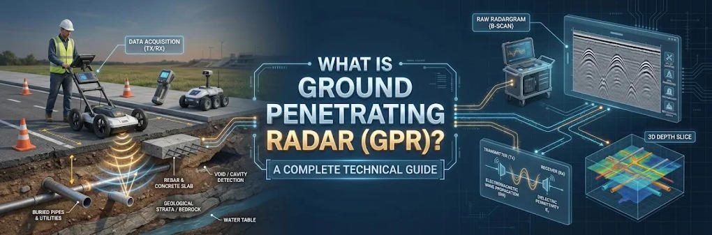
Ground Penetrating Radar (GPR) is a non-destructive geophysical survey technology that uses high-frequency electromagnetic waves to investigate subsurface structures and buried objects. By transmitting electromagnetic pulses into the ground and recording reflected signals from underground interfaces, GPR produces continuous profiles that help engineers identify buried utilities, geological boundaries, voids, concrete reinforcement, and other subsurface anomalies.
Unlike excavation-based investigation, GPR surveys can examine underground conditions without physically disturbing the surveyed area. This makes the technology particularly valuable for civil engineering, infrastructure inspection, geological exploration, underground utility mapping, and archaeological investigation.
GPR is an electromagnetic geophysical method. Its performance depends on the electrical properties of subsurface materials, the antenna frequency, target characteristics, and survey conditions.
Quick Answer: How Does Ground Penetrating Radar Work?
Ground Penetrating Radar works by transmitting short electromagnetic pulses into the ground and recording the energy reflected from subsurface boundaries with contrasting electrical properties. By analyzing signal travel time, amplitude, and waveform characteristics, engineers generate radargrams that help interpret the location, depth, geometry, and distribution of underground features.
Ⅱ. How Does Ground Penetrating Radar Work?
The operating principle of GPR is based on electromagnetic wave propagation and reflection.
A typical GPR survey follows four basic steps:
Step 1: Electromagnetic Pulse Transmission
The transmitting antenna generates short-duration electromagnetic pulses at a selected center frequency. These pulses travel through the ground or the material being investigated.
Step 2: Interaction with Underground Materials
When electromagnetic waves encounter boundaries between materials with different dielectric properties, part of the transmitted energy may be reflected, while the remaining energy continues propagating into deeper materials.
Examples include:
- Soil and bedrock interfaces.
- Soil layers with different moisture contents.
- Underground pipes surrounded by soil.
- Concrete reinforcement and surrounding concrete.
- Air-filled voids and geological cavities.
Step 3: Receiving Reflected Signals
The receiving antenna records returning electromagnetic energy. The system measures signal amplitude and two-way travel time (TWT), together with other waveform information.
Step 4: Data Processing and Subsurface Interpretation
The collected signals are displayed as radargrams. Engineers use signal characteristics, travel-time analysis, velocity estimation, and spatial relationships to interpret underground structures.
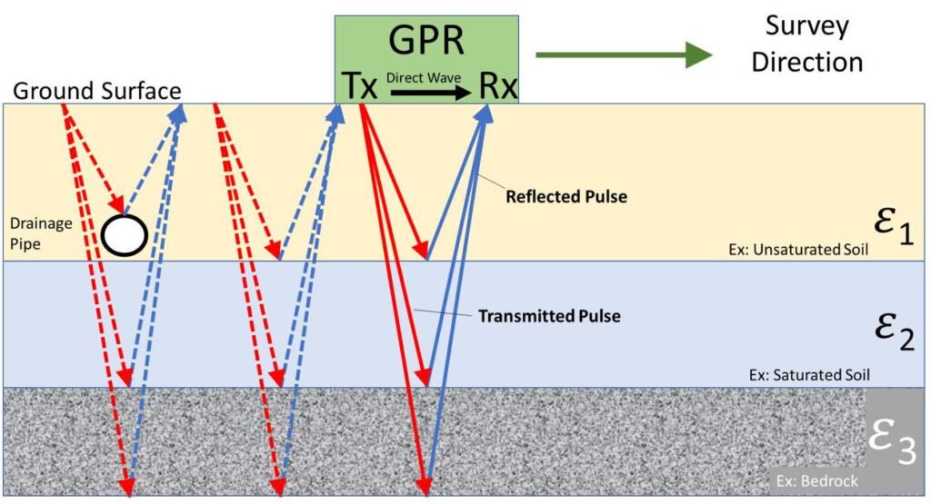
Figure 1. Conceptual illustration of GPR electromagnetic wave transmission and reflection. This is a technical illustration, not an actual survey result.
How Is Underground Depth Estimated?
GPR primarily measures the time required for electromagnetic energy to travel from the antenna to a reflecting interface and return.
If the average electromagnetic wave velocity is known or estimated, the reflector depth can be calculated using:
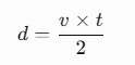
Where:
- d = estimated reflector depth.
- v = average electromagnetic wave velocity.
- t = two-way travel time.
The factor of two accounts for the downward and upward travel paths.
For many non-magnetic geological materials, wave velocity can be approximated by:
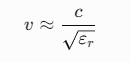
Where:

This relationship provides a theoretical basis for depth estimation. However, actual subsurface materials are heterogeneous, and inaccurate velocity assumptions can produce significant depth errors. Calibration using known-depth targets or suitable velocity-analysis techniques is therefore important.
Ⅲ. Main Components of a GPR System
A Ground Penetrating Radar system generally consists of several interconnected components. The exact configuration depends on the equipment design, antenna type, positioning requirements, and intended application.
| Component | Main Function |
|---|---|
| Control Unit / Mainframe | Controls signal transmission, reception, acquisition parameters, and system operation |
| Transmitting Antenna | Radiates electromagnetic pulses into the ground or structure |
| Receiving Antenna | Detects reflected electromagnetic signals |
| Distance Encoder | Records survey distance and helps maintain spatial trace positioning |
| Positioning Module | Provides geographic or trajectory information when configured |
| Data Acquisition Software | Displays and records radar signals during fieldwork |
| Processing and Interpretation Software | Supports filtering, velocity analysis, depth conversion, and radargram interpretation |
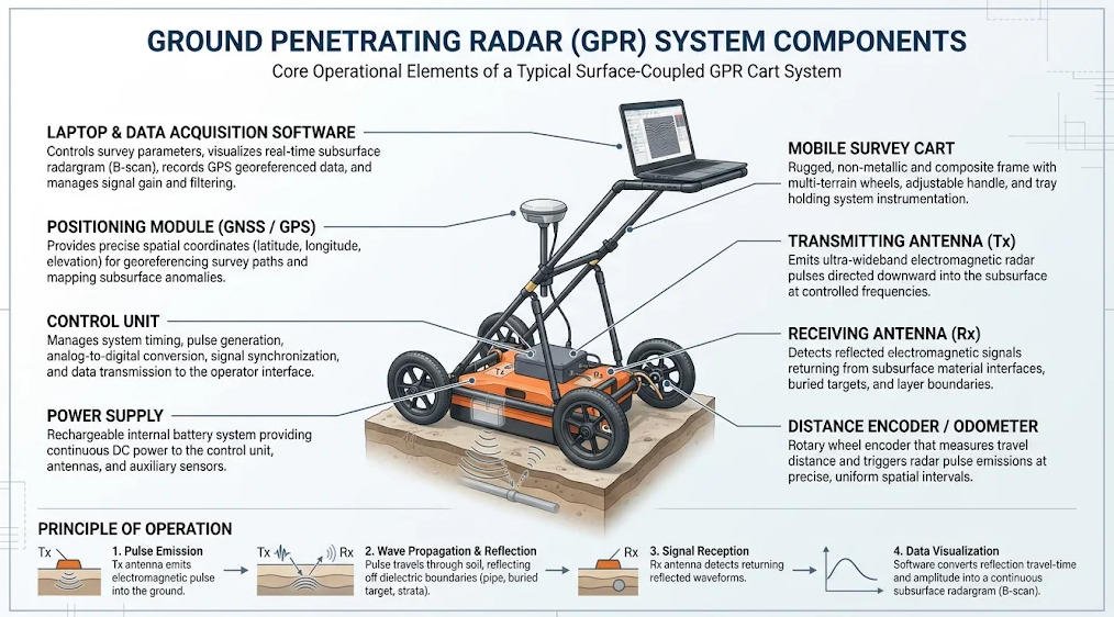
Figure 2. Typical GPR system architecture and major functional components. Actual configurations vary between systems.
Some GPR instruments integrate the transmitter, receiver, antenna, and battery into one portable unit. Other systems use separate control units, interchangeable antennas, vehicle-mounted arrays, or specialized positioning equipment.
For multi-channel 3D systems, additional antenna elements and positioning arrangements enable dense spatial data acquisition over larger survey areas.
Ⅳ. What Can Ground Penetrating Radar Detect?
GPR identifies subsurface features through electromagnetic responses associated with changes in material properties. It does not directly photograph underground objects or automatically identify every material.
Common targets include:
Underground Utilities
- Metallic water pipes.
- PVC and other non-metallic pipelines.
- Electrical conduits.
- Communication ducts.
- Drainage systems.
Geological Structures
- Soil and rock interfaces.
- Bedrock depth and surface variations.
- Geological layering.
- Fracture zones.
- Karst-related anomalies.
- Buried geological structures.
Voids and Underground Anomalies
- Air-filled cavities.
- Underground voids.
- Abandoned underground structures.
- Localized disturbed ground.
- Potential subsurface collapse zones.
Concrete and Infrastructure Structures
- Reinforcing steel bars (rebar).
- Post-tensioning ducts.
- Concrete layer interfaces.
- Delamination and potential voids.
- Pavement structural layers.
Archaeological Features
- Buried foundations.
- Historical building remains.
- Tomb structures.
- Archaeological boundaries and disturbed soil zones.
The reliability of detection depends on target size, depth, orientation, material contrast, antenna frequency, and surrounding conditions.
An important engineering distinction is that a radar anomaly is not automatically proof of a specific underground object. Interpretation should consider the geological setting and, where necessary, be confirmed using complementary investigation methods.
Ⅴ. Major Applications of Ground Penetrating Radar
GPR has applications across several engineering and scientific disciplines.
| Application | Typical Investigation Targets |
|---|---|
| Geological Exploration | Bedrock interfaces, geological structures, cavities and fractures |
| Underground Utility Survey | Buried water pipes, cables, conduits and drainage systems |
| Road Engineering | Pavement thickness, subsurface voids and structural interfaces |
| Bridge Inspection | Reinforcement, concrete thickness and potential deterioration zones |
| Tunnel Engineering | Lining thickness, geological anomalies and potential voids |
| Building Inspection | Rebar, embedded objects and concrete defects |
| Archaeology | Buried structures and historical remains |
| Environmental Investigation | Buried objects, disturbed ground and selected subsurface interfaces |
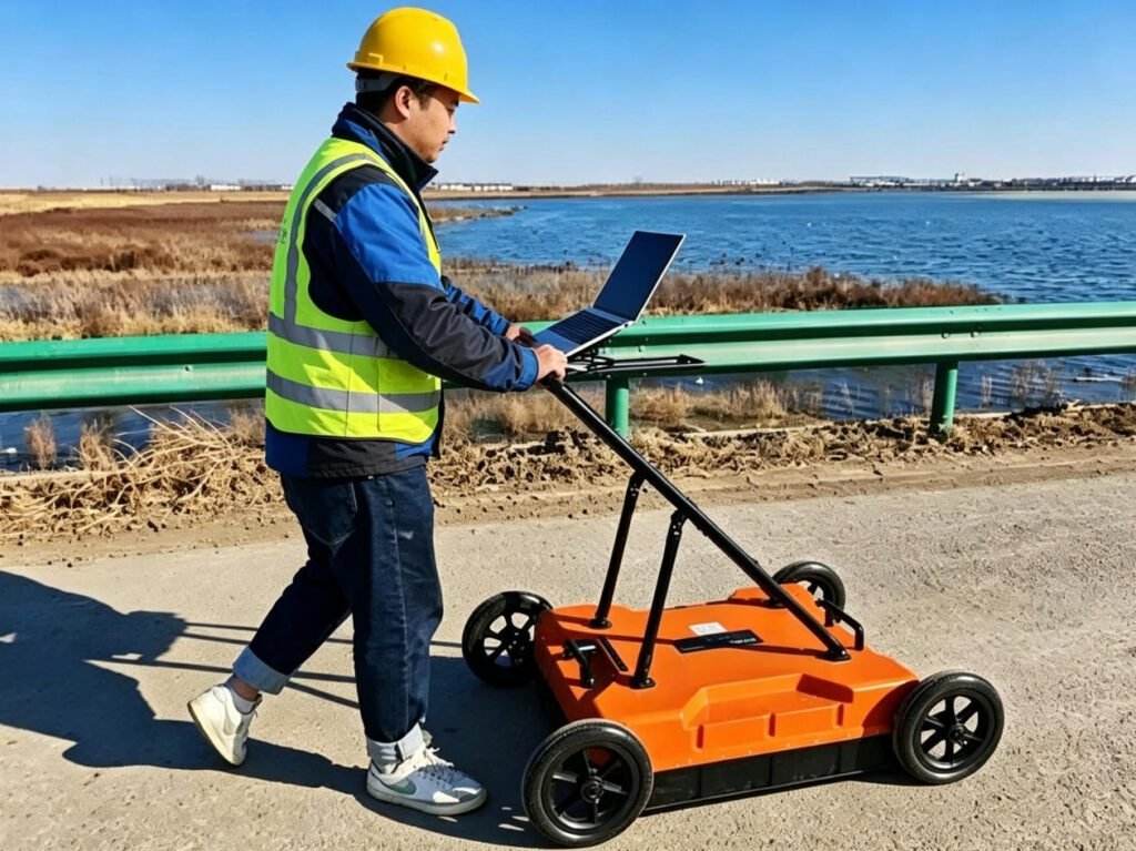
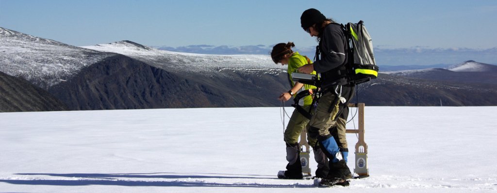
Figure 3. Example of a ground-coupled GPR field survey for infrastructure and underground utility investigation.
GPR can also be deployed using different survey configurations:
- Ground-coupled GPR: Antennas operate close to or in contact with the survey surface.
- Air-coupled GPR: Antennas operate above the surface, commonly for rapid pavement and road surveys.
- Borehole GPR: Specialized antennas investigate surrounding formations from boreholes.
- Multi-channel 3D GPR: Multiple antenna channels collect dense spatial information for volumetric subsurface imaging.
The appropriate configuration depends on survey access, target geometry, required coverage, and investigation objectives.
Ⅵ. Key Factors Affecting GPR Performance
GPR performance is strongly influenced by subsurface conditions and equipment configuration. Understanding these factors is essential before selecting a system or estimating achievable investigation depth.
6.1 Dielectric Permittivity
Dielectric permittivity influences electromagnetic wave velocity and reflection behavior. Interfaces with sufficient dielectric contrast can produce detectable reflections.
Changes in water content often create significant variations in dielectric properties.
6.2 Electrical Conductivity
Electrical conductivity is one of the most important factors controlling radar signal attenuation.
Conductive materials absorb electromagnetic energy, reducing the strength of signals returning from deeper targets.
Clay-rich soils, saline groundwater, and highly conductive materials can substantially restrict penetration.
6.3 Soil Moisture
Water content changes dielectric properties and generally increases attenuation under many field conditions.
Consequently, a survey conducted in dry soil may produce different results from one conducted in the same location after heavy rainfall.
6.4 Clay and Salinity
Fine-grained clay minerals and dissolved salts can increase electrical conductivity and reduce radar penetration.
This is why GPR performance in conductive clay-rich ground is often significantly poorer than in dry, clean sand or low-loss rock.
6.5 Antenna Frequency
Antenna frequency involves a fundamental compromise between penetration depth and resolution.
| Antenna Frequency | General Characteristics | Typical Investigation |
|---|---|---|
| Low Frequency | Greater potential penetration, lower spatial resolution | Geological structures and deeper interfaces |
| Medium Frequency | Balanced penetration and resolution | Utilities, roads and general engineering surveys |
| High Frequency | Higher resolution, shallower investigation | Concrete, reinforcement and shallow structures |
These are general selection principles, not guaranteed depth ranges. Actual performance depends on site conditions and antenna design.
6.6 Target Size and Orientation
Small targets may produce weak or ambiguous reflections. Target orientation relative to the antenna and survey direction can also influence the recorded response.
Survey lines in multiple directions may improve confidence when investigating linear utilities or complex structures.
Ⅶ. Advantages and Limitations of GPR
Ground Penetrating Radar offers several advantages compared with intrusive investigation methods, but it is not universally suitable for every geological environment.
| Advantages | Limitations |
|---|---|
| Non-destructive investigation | Limited penetration in conductive soils |
| Continuous subsurface profiling | Performance affected by moisture and clay |
| High-resolution shallow imaging | Depth estimation requires velocity calibration |
| Rapid data acquisition | Interpretation requires technical experience |
| Detects metallic and non-metallic targets | Some small or low-contrast targets may be difficult to identify |
| Multiple engineering applications | Results may require complementary verification |
One important advantage is that GPR can detect certain non-metallic underground utilities that conventional electromagnetic utility locators may not identify effectively.
However, GPR should not be treated as a universal replacement for electromagnetic locating, electrical resistivity tomography (ERT), seismic methods, or direct verification.
The most reliable investigation strategy is often to combine methods according to the geological conditions and project requirements.
Ⅷ. How to Select a Suitable Ground Penetrating Radar System
Selecting a GPR system should begin with the engineering objective rather than the equipment specification alone.
The following factors should be considered:
- Target Depth: Determine the expected investigation depth and whether the target is shallow or deep.
- Target Size: Small objects and thin structural layers generally require higher spatial resolution.
- Site Conditions: Evaluate soil moisture, clay content, salinity, surface conditions, and expected signal attenuation.
- Survey Area: Consider whether the project involves a small concrete structure, road corridor, tunnel, or large geological investigation area.
- Acquisition Efficiency: Assess the required survey speed, trace density, positioning accuracy, and number of channels.
- Data Output: Determine whether the project requires 2D radargrams, depth slices, georeferenced maps, or 3D subsurface models.
Practical Comparison of GPR System Configurations
| System Type | Suitable Applications | Main Consideration |
|---|---|---|
| Single-Frequency GPR | General-purpose surveys | Frequency must match target requirements |
| Dual-Frequency GPR | Surveys requiring complementary depth and resolution | Two frequency bands provide different information |
| Step-Frequency GPR | Detailed near-surface and structural investigation | Frequency sweep and processing requirements |
| Deep-Penetration GPR | Geological and deeper subsurface investigation | Requires favorable low-loss conditions |
| Air-Coupled GPR | Road and pavement surveys | Efficient non-contact data acquisition |
| Borehole GPR | Borehole-based geological investigation | Requires suitable borehole access |
| Multi-Channel 3D GPR | Large-area infrastructure and utility mapping | Higher spatial coverage and data-processing requirements |
For example, a concrete inspection project may prioritize high-frequency antennas and detailed near-surface resolution, whereas a geological investigation may require lower-frequency antennas to investigate deeper interfaces.
For large-area infrastructure projects, multi-channel systems can reduce the number of individual survey lines required to achieve dense spatial coverage.
Ⅸ. GEO-GPR Ground Penetrating Radar Product Portfolio
Geotech Instrument Co., Ltd. provides different GPR equipment configurations for geological exploration, infrastructure inspection, underground utility mapping, and engineering applications.
The GEO-GPR portfolio includes several equipment categories:
- Single-Frequency GPR: Designed for surveys with clearly defined investigation and resolution requirements.
- Dual-Frequency GPR: Combines complementary frequency bands for projects requiring different levels of penetration and resolution.
- GEO-GPR-U Deep-Penetration GPR: Designed for deeper geological investigation using interchangeable low-frequency antennas.
- GEO-GPR-RCS Step-Frequency GPR: Uses stepped-frequency technology for wideband subsurface inspection.
- GEO-GPR-A Air-Coupled GPR: Intended for non-contact surface survey configurations.
- GEO-GPR-BRD Borehole GPR: Designed for borehole-based subsurface investigation.
- GEO-GPR-3D-P Push-Type Multi-Channel 3D GPR: Designed for walk-behind, multi-channel volumetric survey applications.
- GEO-GPR-3D-V Vehicle-Mounted 3D GPR: Designed for efficient large-area infrastructure and road investigation.
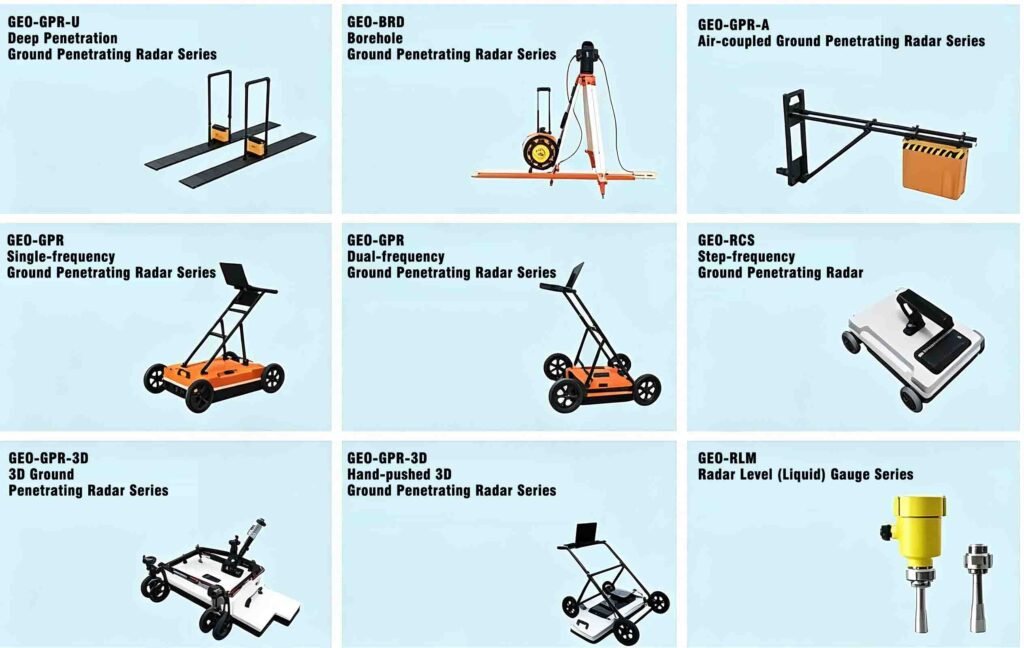
The selection of a suitable system should consider the investigation objective, expected target depth, required resolution, geological conditions, survey efficiency, and final data format.
For detailed product configurations and technical specifications, refer to the relevant GEO-GPR product pages or contact Geotech for application-specific equipment recommendations.
Ⅹ. Conclusion
Ground Penetrating Radar is a versatile non-destructive geophysical technology for investigating shallow and, under suitable conditions, deeper subsurface structures.
Its effectiveness depends on the interaction between electromagnetic waves and underground materials, particularly dielectric properties, electrical conductivity, moisture content, antenna frequency, and target geometry.
Understanding these factors is essential for selecting suitable equipment, planning reliable surveys, and interpreting radar data correctly.
For engineering professionals and GPR equipment buyers, the best system is not necessarily the one with the highest frequency, greatest advertised penetration depth, or largest number of channels. It is the system whose configuration matches the actual investigation requirements and site conditions.
Geotech Instrument Co., Ltd. offers a range of GEO-GPR configurations for different geological and engineering applications, supporting informed equipment selection for professional subsurface investigation.
Related Articles
| Recommended Anchor Text | Target URL |
|---|---|
| Ground Penetrating Radar Equipment | GPR Product Category |
| Deep-Penetration Geological GPR | GEO-GPR-U |
| Step-Frequency Ground Penetrating Radar | GEO-GPR-RCS |
| Push-Type Multi-Channel 3D GPR | GEO-GPR-3D-P |
| Vehicle-Mounted 3D GPR System | GEO-GPR-3D-V |
| Borehole Ground Penetrating Radar | GEO-GPR-BRD |
Reference Sources
| Authority Source | Recommended Reference |
|---|---|
| U.S. Environmental Protection Agency (EPA) | Ground Penetrating Radar (GPR) |
| Federal Highway Administration (FHWA) | Site Characterization and Utility Locating |
| FHWA InfoTechnology | Pavement GPR Investigation |
| ASTM International | ASTM D6432 – Standard Guide for Surface GPR |
| USDA Natural Resources Conservation Service | Ground Penetrating Radar Fact Sheet |
FAQ
1. What is Ground Penetrating Radar used for?
Ground Penetrating Radar is used to investigate underground utilities, geological structures, buried objects, subsurface voids, concrete reinforcement, pavement layers, and infrastructure defects. It is widely applied in civil engineering, geological exploration, utility mapping, road inspection, and archaeology.
2. How deep can Ground Penetrating Radar detect?
GPR detection depth depends on antenna frequency, soil conductivity, moisture content, clay content, target characteristics, and equipment configuration. Lower-frequency antennas generally provide greater penetration, while higher-frequency antennas provide better resolution. There is no universal detection depth applicable to every site.
3. Can GPR detect non-metallic underground pipes?
Yes. GPR can detect certain non-metallic pipes, including PVC and other plastic utilities, when sufficient electromagnetic contrast exists between the pipe, its contents, and surrounding soil. Detection reliability depends on pipe diameter, burial depth, orientation, and ground conditions.
4. What is the difference between low-frequency and high-frequency GPR?
Low-frequency GPR generally provides greater penetration depth but lower spatial resolution. High-frequency GPR provides better resolution for small or shallow targets but usually experiences greater attenuation. Antenna frequency should be selected according to the investigation objective.
5. Can Ground Penetrating Radar work in wet or clay-rich soil?
GPR can operate in wet or clay-rich soil, but its performance may be significantly reduced. Increased electrical conductivity causes greater electromagnetic attenuation, limiting penetration depth and reducing the strength of reflected signals. Site testing is recommended before a large-scale survey.
6. What is the difference between 2D GPR and 3D GPR?
2D GPR typically produces cross-sectional radargrams along individual survey lines. Multi-channel 3D GPR collects spatially distributed data across an area, allowing engineers to generate depth slices, plan-view maps, and volumetric subsurface models. Three-dimensional imaging requires appropriate spatial sampling and processing.
7. Is Ground Penetrating Radar a non-destructive testing method?
Yes. GPR is generally classified as a non-destructive investigation method because it uses electromagnetic waves rather than excavation or physical sampling. However, interpreted anomalies should be verified using suitable complementary methods when project safety or engineering acceptance requires confirmation.