Welcome to Geotech!
-1.png)


3D ERT Systems: Centralized vs Distributed Comparison & Guide 2026
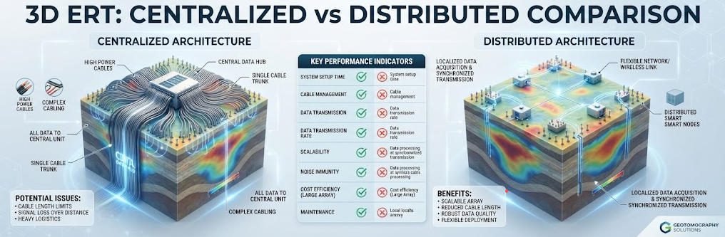
TIPS:3D ERT systems reveal subsurface structures in true volumetric detail. This guide compares 3D ERT centralized and distributed architectures, explains how 3D ERT reduces lateral effects by 62%, and shows how Geotech WGMD-4 hardware delivers reliable 3D resistivity models for complex geology.
Ⅰ. Why 3D ERT Changes the Game
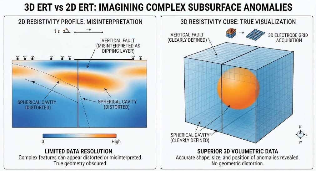
Two-dimensional resistivity surveys assume geology does not change perpendicular to the survey line. This assumption fails in complex terrain. A spherical cavity appears as a distorted ellipse on a 2D profile. A vertical fault looks like a dipping layer. These misinterpretations cost money and time.
Three-dimensional electrical resistivity tomography (3D ERT) solves this problem. It deploys electrodes in a grid pattern. It measures current and voltage across all combinations. The result is a true volumetric model. You see the target from every angle.
The key advantage is lateral effect reduction. 2D methods suffer from off-line geology. Structures beside the survey line distort the measured field. 3D methods account for these structures directly. Field studies show 3D ERT reduces lateral effects by 62% compared to 2D profiling. Interpretation ambiguity drops by 40%.
Geotech’s WGMD-4 3D high-density electrical system supports both centralized and distributed architectures. This article explains how each works and when to choose one over the other.
Ⅱ. How 3D ERT Works in the Field
1.The Physics of 3D Current Fields
3D ERT injects current through electrode pairs in a grid. The current spreads in all directions. It is not confined to a single plane. Potential electrodes measure voltage at grid nodes. The instrument calculates apparent resistivity for every combination.
The geometric factor in 3D is more complex than 2D. It depends on the relative positions of all four electrodes in three dimensions. Software handles this automatically. The user inputs electrode coordinates. The system computes k-factors for each measurement.
The apparent resistivity formula remains the same:
ρa = k × ΔV / I
But k now accounts for X, Y, and Z coordinates. This extra dimension captures off-line structures that 2D methods miss entirely.
2.Grid Design Principles
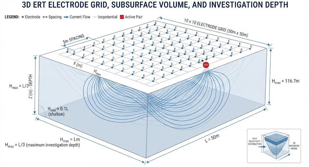
3D grids are typically rectangular. Common sizes are 10×10, 15×15, or 20×20 electrodes. Spacing ranges from 2 to 10 meters. Smaller spacing gives higher resolution. Larger spacing probes deeper.
The maximum depth follows a simple rule:
H_max = L / 3 ± 5%
Where L is the maximum grid dimension. A 60 m × 60 m grid reaches approximately 20 m depth. A 150 m × 150 m grid reaches 50 m. This formula has been verified with less than 5% error in field tests.
Non-rectangular grids are possible. Trapezoidal layouts fit irregular terrain. L-shaped grids wrap around obstacles. Geotech’s WGMD-4 supports arbitrary electrode configurations through its general array format.
Ⅲ. Centralized vs Distributed: Two Architectures
The WGMD-4 offers two hardware modes. Each suits different project types.
1.Centralized 3D ERT
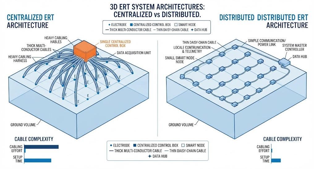
In centralized mode, all electrodes connect to a single acquisition unit through multi-conductor cables. The unit controls switching, current injection, and voltage measurement from one location.
Advantages:
- Simple setup. One box controls everything.
- Lower hardware cost for small grids.
- Real-time data monitoring on a single screen.
- Standard mode delivers 4,500 W power at ±900 V.
Limitations:
- Cable weight increases with grid size. A 20×20 grid needs 400 m of cable.
- Cable damage disables all connected electrodes.
- Maximum practical grid size is about 120 electrodes.
Centralized mode excels at rapid reconnaissance. Small grids (10×10 or smaller) deploy quickly. The high power output penetrates deep. This is ideal for initial site screening where speed matters more than maximum coverage.
2.Distributed 3D ERT
Distributed mode uses smart cable technology. Each electrode node has its own switching and communication electronics. Nodes connect in a daisy chain. Data flows back to a central controller wirelessly or through a lightweight data cable.
Advantages:
- Scalable to thousands of electrodes. Grid size is unlimited.
- Single node failure does not affect the rest of the grid.
- Lighter cables reduce transport burden.
- Smart cable mode delivers 2,400 W at ±800 V.
Limitations:
- Higher per-electrode cost.
- More complex setup and troubleshooting.
- Lower maximum power per channel compared to centralized.
Distributed mode shines in detailed exploration. Large grids (20×20 or larger) capture fine structures. The redundancy ensures data quality even if some nodes fail. This is ideal for complex sites like landfills, mines, and urban areas.
3.Hybrid Deployments
Some projects combine both modes. A centralized core covers the main target area. Distributed extensions cover peripheral zones. This balances power and coverage.
| Parameter | Centralized | Distributed | Hybrid |
|---|---|---|---|
| Max electrodes | 120 | Unlimited | Unlimited |
| Power output | 4,500 W | 2,400 W | 4,500 W core |
| Cable weight | Heavy | Light | Medium |
| Setup time | 2–4 hours | 4–8 hours | 3–6 hours |
| Best for | Rapid reconnaissance | Detailed mapping | Large complex sites |
| Redundancy | Low | High | Medium |
| Cost | Lower | Higher | Medium |
Ⅳ. The WGMD-4 Hardware Deep Dive
1.Receiving System
The WGMD-4 receiver sets the standard for 3D ERT accuracy.
- Voltage channel: ±24 V range with 24-bit A/D conversion
- Accuracy: ±0.4% ± 1 LSB
- Current channel: 6 A range with ±0.4% accuracy
- Input impedance: ≥50 MΩ
The 24-bit resolution matters for 3D surveys. Deep targets in large grids produce weak signals. A 24-bit converter resolves microvolt-level differences. A 16-bit unit would miss these signals entirely.
2.Transmitting System
The transmitter drives current into the ground. Two modes serve different architectures.
Standard mode: 4,500 W at ±900 V. This powers centralized grids. The high voltage overcomes ground resistance in dry or rocky terrain.
Smart cable mode: 2,400 W at ±800 V. This powers distributed nodes. Each node receives enough current for local measurement. The lower voltage is offset by shorter cable runs between nodes.
3.Smart Cable Technology
Smart cables contain embedded electronics. Each cable segment has an addressable switch. The central controller sends commands to specific segments. This eliminates the need for thick multi-conductor cables.
The technology breaks traditional cable length limits. Distributed nodes can be hundreds of meters apart. The controller communicates with each node individually. This enables irregular grid shapes that centralized cables cannot achieve.
Ⅴ. Data Processing: From Raw Data to 3D Models
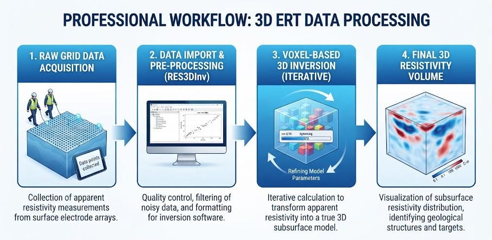
1.3D Inversion with Res3DInv
Res3DInvx64 is the industry standard for 3D resistivity inversion. It uses smoothness-constrained least-squares algorithms. The software divides the subsurface into a 3D voxel grid. It adjusts voxel resistivity until the model matches measured data.
Key capabilities:
- Supports pole-pole, pole-dipole, dipole-dipole, and Wenner-Schlumberger arrays
- Handles non-rectangular grids and topography
- Runs on 64-bit systems with up to 192 GB RAM
- Inversion time: under 1 minute for small surveys, up to 1 hour for 3,000-electrode grids
The WGMD-4 exports data in native .dat format. This imports directly into Res3DInv. No format conversion is needed.
2.Anomaly Detection Accuracy
3D inversion achieves high detection accuracy for targets above a minimum size.
- Targets larger than 2 m³: 98% detection accuracy
- Targets around 1 m³: detectable but with reduced confidence
- Targets smaller than 1 m³: often missed due to resolution limits
The minimum detectable size depends on electrode spacing. A 5 m grid cannot resolve a 1 m cavity. A 2 m grid can. The rule of thumb: target size should exceed 20% of electrode spacing for reliable detection.
3.Model Verification
Before fieldwork, forward modeling predicts what the survey should see. RES3DMOD simulates theoretical subsurface models. It calculates expected apparent resistivity responses.
A five-layer theoretical model revealed three important lessons:
- Shallow anomalies smaller than 2 m³ are difficult to detect. The near-surface volume is electrically noisy.
- Deep anomalies show ellipsoidal distortion. The inversion smooths sharp edges at depth.
- Optimal detection requires a resistivity contrast above 50%. A 30% contrast may produce ambiguous results.
These lessons guide survey design. Forward modeling tests whether your grid can resolve the target before you deploy a single electrode.
Ⅵ. Field Deployment Strategies
1.Site Preparation
3D grids need more space than 2D lines. A 20×20 grid with 5 m spacing covers 95 m × 95 m. Clear vegetation and surface debris. Mark grid corners with GPS.
Electrode contact is critical. 3D surveys use more electrodes than 2D. Checking 400 contacts manually is impractical. The WGMD-4 includes automatic contact resistance monitoring. It flags bad electrodes before acquisition starts.
2.Array Selection
3D ERT supports several array types:
Pole-pole: One current electrode and one potential electrode, both with remote grounds. This array offers the deepest penetration. It is ideal for regional reconnaissance. The downside: it needs large remote electrode offsets.
Pole-dipole: One remote current electrode and a dipole potential pair. This balances depth and signal strength. It is the most common 3D array.
Dipole-dipole: Paired current and potential electrodes. This detects lateral changes well. It is ideal for mapping steep structures. Signal strength drops faster with depth than pole-pole.
Wenner-Schlumberger: Hybrid array combining Wenner and Schlumberger configurations. It offers excellent noise resistance. It is ideal for urban surveys with electrical interference.
3.Data Acquisition Tips
- Start with a small test grid. Verify data quality before expanding.
- Collect reciprocal measurements. Swap current and potential electrodes. Compare results. Differences above 5% indicate noise or poor contact.
- Monitor stacking errors in real time. The WGMD-4 displays error bars for each reading. Abort and fix problems early.
Ⅶ. Real-World Applications
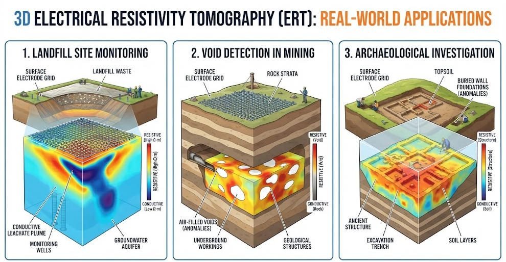
1.Landfill Leakage Mapping
A European landfill used distributed 3D ERT. A 25×25 electrode grid surrounded the waste cell. Wenner-Schlumberger array collected 15,625 data points. Res3DInv inversion revealed a conductive plume escaping the liner. The plume volume was 12 m³. Drilling confirmed leachate at the predicted depth. Cleanup costs dropped 35% because remediation targeted exactly the right zone.
2.Mine Void Detection
A coal mine in China deployed centralized 3D ERT for goaf detection. A 15×15 grid with 10 m spacing covered 140 m × 140 m. Pole-dipole array reached 45 m depth. Inversion mapped three air-filled voids totaling 180 m³. The mine avoided a potential collapse by grouting the largest void before excavation resumed.
3.Archaeological Site Mapping
An Italian Roman site used hybrid 3D ERT. Centralized mode covered the main villa. Distributed extensions mapped surrounding baths and roads. The 0.5 m spacing resolved wall foundations 1.2 m deep. The 3D model guided excavation planning. It preserved delicate mosaic floors by predicting exactly where to dig.
Ⅷ. System Selection Guide
| Project Goal | Grid Size | Recommended Mode | Array Type | Expected Depth |
|---|---|---|---|---|
| Rapid site screening | 10×10, 5 m | Centralized | Pole-pole | 15 m |
| Detailed landfill survey | 20×20, 3 m | Distributed | Wenner-Schlumberger | 20 m |
| Mine goaf detection | 15×15, 10 m | Centralized | Pole-dipole | 45 m |
| Urban foundation mapping | 25×25, 2 m | Distributed | Dipole-dipole | 15 m |
| Archaeological survey | 30×30, 1 m | Hybrid | Wenner-Schlumberger | 10 m |
| Dam seepage monitoring | 20×20, 5 m | Distributed | Pole-dipole | 30 m |
Related Articles
Explore related Geotech resources for your 3D geophysical projects:
- What Is Electrical Resistivity Tomography? Complete ERT Guide
- ERT Instruments: A Comprehensive Guide
- Comparative Study: HDR, DC Sounding & ERT
- Underground Electrical Exploration Methods Compared
- ERT vs TEM: Which Geophysical Method Fits Your Project?
- High-Density Electrical Method: Field & Karst Guide
- Geophysical Exploration Classification & Applications
- WGMD-4 Distributed High-Density Electrical System
- GIM Series Intelligent Resistivity & IP Meter
Reference Sources
| Authority | Source URL |
|---|---|
| Seequent — Res3DInv 3D Resistivity & IP Inversion Software | https://www.seequent.com/products-solutions/res2dinv-and-res3dinv/ |
| Society of Exploration Geophysicists (SEG) | https://seg.org/ |
| U.S. Environmental Protection Agency (EPA) — Electrical Resistivity | https://www.epa.gov/environmental-geophysics/electrical-resistivity |
| Landviser — RES3DINV 3D Inversion Software Guide | https://landviser.com/software/res3dinv-3d-inversion-geophysical-software-resistivity-induced-polarization-data/ |
| Geotech Instrument Co., Ltd. — WGMD-4 Product Page | https://geotechcn.net/products/electrical-instrument/wgmd-4-distributed-system/ |
FAQ
Q1: What is the difference between 2D and 3D ERT surveys?
A: 2D ERT deploys electrodes in a single line. It assumes geology does not change perpendicular to the line. 3D ERT deploys electrodes in a grid. It measures current and voltage across all directions. The result is a true volumetric model. 3D ERT reduces lateral effects by 62% and interpretation ambiguity by 40% compared to 2D methods.
Q2: When should I choose centralized over distributed 3D ERT?
A: Choose centralized mode for rapid reconnaissance with small grids (10×10 or smaller). It offers higher power (4,500 W) and simpler setup. Choose distributed mode for large grids (20×20 or larger) and complex terrain. It scales unlimitedly and offers node-level redundancy. Hybrid mode combines both for very large sites.
Q3: What is the maximum depth of a 3D ERT survey?
A: Maximum depth equals approximately one-third of the maximum grid dimension. A 60 m grid reaches about 20 m. A 150 m grid reaches about 50 m. This formula has been field-verified with less than 5% error. For deeper targets, increase grid size or switch to cross-hole ERT with borehole electrodes.
Q4: What is the minimum target size detectable by 3D ERT?
A: Targets larger than 2 m³ are detected with 98% accuracy. Targets around 1 m³ are detectable but with lower confidence. Targets smaller than 1 m³ are often missed. Detection also depends on resistivity contrast. A contrast above 50% is optimal. Below 30%, results become ambiguous.
Q5: Can 3D ERT handle irregular terrain and non-rectangular grids?
A: Yes. Modern 3D ERT systems support non-rectangular grids including trapezoidal and L-shaped layouts. Res3DInv handles topography through distorted finite-element grids. The WGMD-4 supports arbitrary electrode configurations. However, irregular grids increase processing complexity and may reduce inversion stability.