Welcome to Geotech!
-1.png)


What is ERI ?丨Electrical vs Electromagnetic Geophysical Survey
TIPS:Choosing between an electrical geophysical survey and an electromagnetic geophysical survey directly impacts project cost, data quality and interpretive confidence. An electrical geophysical survey injects controlled ground current via electrodes to map subsurface resistivity, delivering high‑resolution near‑surface imaging but requiring galvanic ground contact. An electromagnetic geophysical survey generates alternating magnetic fields to induce subsurface eddy currents without electrode insertion, supporting fast regional reconnaissance and deep probing, yet suffers from shallow blind zones. This article compares physical principles, field workflows, limitations and real‑world applications to help geophysicists select or combine these two critical near‑surface exploration techniques.
Ⅰ. Introduction
Geophysical near‑surface characterization relies heavily on electrical‑family and electromagnetic‑family methods. Both techniques map subsurface variations in electrical resistivity or conductivity, but their physical mechanisms, field hardware, performance envelopes and failure modes differ fundamentally.
Many practicing geophysicists struggle with practical decisions: Should I deploy electrical resistivity tomography (ERT), or select electromagnetic (EM) tools for my site? Can one method replace the other? Under what geological and surface conditions should I combine both approaches?
This article provides technically grounded, field‑oriented comparison. It covers core physical principles, field operational workflows, measurable performance metrics, geological limitations, typical project fit, equipment selection considerations, and best‑practice hybrid survey workflows. All technical statements align with SEG guidance, USGS geophysical practice documents and ASTM standards for near‑surface site characterizationUSGS.
This resource targets geophysical engineers, environmental consultants, hydrogeologists, mining geoscientists and technical procurement teams evaluating geophysical survey solutions and instruments.
Ⅱ. Core Working Principles
1. Electrical Geophysical Survey Principles
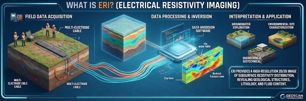
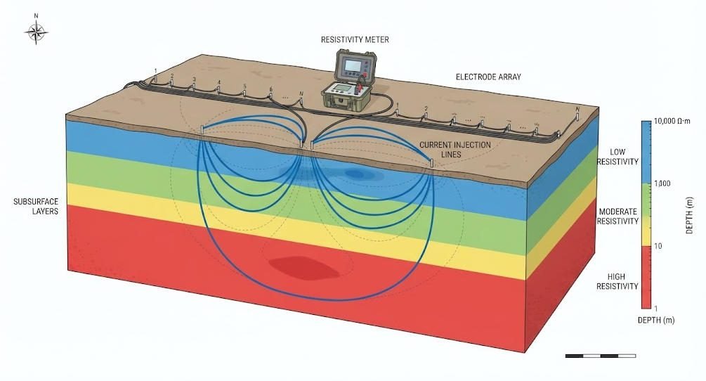
Electrical geophysical methods are galvanic‑contact techniques. Systems inject controlled direct‑current (DC) or low‑frequency alternating current (AC) into subsurface formations via physical ground electrodes. Separate electrodes measure resulting potential differences across the ground surface.
Subsurface rock, soil and fluid units exhibit distinct resistivity values. Dry hard rock may exceed 1 000 000 Ω·m, water‑bearing unconsolidated sediment typically ranges from 1 – 100 Ω·m. By measuring voltage responses under known injected current, instruments calculate apparent resistivity. Modern multi‑electrode ERT systems collect datasets across multiple array geometries (Wenner, Schlumberger, dipole‑dipole), then apply tomographic inversion algorithms to reconstruct 2‑D or 3‑D subsurface resistivity models.
Induced‑polarization (IP) extends electrical survey capability. After cutting off injected current, IP measures voltage decay caused by charge accumulation on mineral grain boundaries. IP delivers extra chargeability parameters, extremely valuable for disseminated sulfide mineral exploration and clay‑rich lithology discrimination.
Key requirement: electrodes must achieve adequate galvanic contact with soil or rock. High‑resistance contact (frozen soil, asphalt pavement, bare dry bedrock) degrades signal quality heavily.
2. Electromagnetic Geophysical Survey Principles
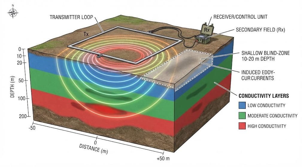
Electromagnetic geophysical methods operate on electromagnetic induction. No galvanic ground contact is mandatory. A transmitter coil generates a time‑varying primary magnetic field. This field penetrates underground and induces closed‑loop eddy currents within conductive subsurface bodies. Those eddy currents decay and radiate secondary magnetic fields, which surface receiver coils record.
Two major EM branches are widely deployed:
- Frequency‑Domain EM (FDEM): Transmit multiple continuous sinusoidal frequencies. Lower frequencies achieve deeper penetration following the skin‑depth equation. Output is apparent conductivity. Mostly used for fast horizontal mapping within roughly 100 m depth.
- Time‑Domain EM (TEM / Transient EM): Transmit a strong current pulse through a large transmitter loop, then abruptly shut off current. Instruments measure how secondary magnetic fields decay over time. Early‑time signals reflect shallow material; late‑time signals correspond to deeper subsurface. TEM achieves much greater depth than FDEM, commonly 200‑800 m depending on loop size and transmit power.
Critical inherent limitation for TEM: shallow blind zone. Early‑time signal noise from transmitter switch‑off contaminates data from approximately 10‑20 m depth. Small near‑surface features cannot be reliably resolved by standalone TEM surveys.
3. Fundamental Mechanism Difference Summary
| Item | Electrical Survey (ERT / DC Resistivity / IP) | Electromagnetic Survey (FDEM / TEM) |
|---|---|---|
| Physical mechanism | Galvanic current injection through ground electrodes | Induction of subsurface eddy currents by magnetic field |
| Ground contact requirement | Mandatory electrode‑soil galvanic contact | No physical contact required |
| Primary measured quantity | Resistivity (+ chargeability for IP) | Conductivity (reciprocal of resistivity) |
| Near‑surface performance | Excellent resolution | TEM has shallow blind‑zone; FDEM moderate |
| Deep performance | Depth limited by total electrode spread length | Large‑loop TEM can achieve >500 m penetration |
| Signal noise source | Poor electrode contact, telluric currents | Power‑line EMI, metallic surface debris, coil misalignment |
Ⅲ. Field Workflow & Operational Comparison
1. Typical Electrical Survey Field Steps
- Layout survey line and install electrode array (24‑120+ electrodes). Improve contact quality by watering dry soil electrode points.
- Connect multi‑core survey cable to each electrode, link cable to main ERT receiver‑transmitter unit.
- Configure array sequence (Wenner‑Schlumberger, dipole‑dipole etc.) on instrument.
- Run automated data acquisition cycle. Instrument switches electrode combinations and records current‑voltage pairs.
- Store raw data with GNSS location markers.
- Post‑process: remove bad‑contact noisy records, run tomographic inversion to generate 2‑D / 3‑D resistivity sections.
Field challenges: Electrode installation is labour‑intensive. Frozen ground, concrete roads, rock outcrops make electrode deployment difficult or impossible. Survey footprint is constrained by physical cable layout.
2. Typical Electromagnetic Survey Field Steps
- Select suitable coil or transmitter‑loop geometry according to target depth. FDEM uses small portable coils; TEM deploys large wire loops for deep targets.
- Position transmitter‑receiver system on ground surface. No ground piercing required.
- Set transmit frequency stack counts (FDEM) or pulse timing parameters (TEM).
- Walk or move coil system along survey profile. Record conductivity / transient decay data synchronised with GNSS coordinates.
- Post‑process raw time‑series data, apply noise filtering, run layered or 2‑D inversion for conductivity‑depth models.
Field advantages: Fast areal coverage. Works on paved ground, frozen soil where electrodes cannot be planted. Major downsides: TEM blind‑zone for shallow targets; strong interference from above‑ground metal fences, power transmission infrastructure.
3. Field Operation Side‑by‑Side Table
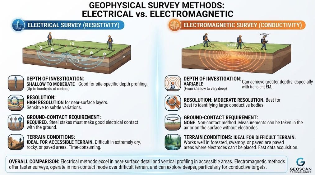
| Operational Parameter | Electrical ERT Survey | Electromagnetic TEM / FDEM Survey |
|---|---|---|
| Field crew size | 2‑4 people for large multi‑electrode spreads | 1‑2 field operators (portable systems) |
| Survey speed | Moderate; limited by electrode deployment | Fast, especially for regional reconnaissance |
| Workable surface conditions | Soil / soft sediment preferred; poor on rock, asphalt, frozen ground | Excellent for pavement, frozen soil, bare rock |
| Physical footprint | Long electrode cables, fixed‑profile layout | Coils / loops; flexible profiling path |
| Urban EMI sensitivity | Moderate (filterable digital noise suppression) | High; power‑lines create severe distortion |
| Typical relative field cost per km profile | Medium‑high (labour heavy) | Medium‑low for reconnaissance scale |
Ⅳ. Performance: Depth, Resolution, Strengths & Limitations
1. Depth Penetration
For ERT: maximum reliable investigation depth approximates 1/3 ~ 1/5 of total electrode array spread length. For example, 120‑electrode array with 5 m spacing yields maximum usable depth around 100‑120 m. Beyond this limit, signal‑to‑noise ratio collapses rapidly.
For EM:
- FDEM portable systems: typical effective depth 10‑80 m.
- TEM: small loop ~150‑250 m; large‑high‑moment loops can exceed 800 m depth. But TEM retains its shallow blind‑zone regardless of loop size.
Important note: Actual achievable depth for both methods is heavily controlled by subsurface geology. Thick highly‑conductive overburden will attenuate signals and reduce effective depth for both survey families.
2. Spatial Resolution
- ERT: Excellent lateral and vertical resolution in near‑surface domain (0.5‑2 m typical under optimal setup). Capable of resolving karst cavities, narrow fracture zones, small contaminant plumes. Resolution degrades progressively with depth.
- FDEM: Moderate lateral resolution, limited vertical layer resolving capability. Best for mapping horizontal conductivity variations.
- TEM: Good vertical layering resolution for deep conductive horizons, but weak lateral resolution, plus the 10‑20 m shallow blind‑zone. Cannot identify small isolated near‑surface anomalies reliably.
3. Core Strengths & Known Limitations
Electrical Survey (ERT / IP)
✅ Strengths
- High‑fidelity near‑surface 2‑D / 3‑D imaging.
- Simultaneous resistivity + induced‑polarization (IP) measurement for mineral discrimination.
- Well‑established inversion workflows, widely accepted within engineering and environmental geophysics.
- Resolves both conductive and resistive subsurface anomalies equally well.
❌ Limitations
- Requires good electrode‑soil contact; fails on impermeable hard surfaces.
- Maximum depth constrained by array physical length.
- Higher field labour cost for large survey grids.
- Susceptible to high contact resistance noise in arid / frozen terrain.
Electromagnetic Survey (FDEM / TEM)
✅ Strengths
- Non‑contact measurement. Works where electrodes cannot be installed.
- TEM achieves deep subsurface penetration.
- High survey speed for regional‑scale reconnaissance mapping.
- Airborne EM variants can map thousands of square kilometres.
❌ Limitations
- TEM shallow blind‑zone prevents detailed top‑of‑subsurface imaging.
- EM methods respond primarily to conductive bodies; poor performance for purely resistive target detection.
- Vulnerable to man‑made metallic interference (fences, pipelines, power lines).
- Inversion non‑uniqueness remains significant, requiring borehole calibrationASTM Inter….
Ⅴ. Project‑Based Method Selection Matrix
This decision matrix supports project planners to select primary or complementary geophysical techniques.
| Project Scenario | Preferred Primary Method | Complementary Option | Key Notes |
|---|---|---|---|
| Karst cavity detection, shallow void mapping (<80 m) | ERT (+IP) | TEM for deep bedrock structure | TEM blind‑zone makes TEM unsuitable standalone for near‑surface cavities |
| Regional deep groundwater aquifer exploration (150‑600 m) | TEM | ERT for calibrating shallow lithology | Use ERT to fill TEM shallow blind‑zone information gap |
| Landfill & contaminant‑plume site assessment | ERT for detailed local mapping | FDEM for large‑site rapid screening | FDEM quickly delineates suspect zones; ERT delivers high‑resolution detail |
| Mineral exploration for disseminated sulphide ore | ERT‑IP integrated system | TEM for deep conductive ore bodies | IP chargeability differentiates mineralized zones vs simple conductive groundwater |
| Site survey on frozen ground / asphalt pavement | FDEM / TEM | ERT only where bare soil patches exist | ERT electrode contact is unfeasible over paved or fully frozen surfaces |
| Engineering foundation site investigation (<100 m) | ERT | EM for extended regional context | ERT gives precise near‑surface stratigraphy for foundation design |
No geophysical method delivers unique subsurface solutions. Whenever feasible, validate geophysical interpretations with borehole data, following ASTM and SEG best‑practice guidanceASTM Inter….
Ⅵ. Integrated Electrical‑Electromagnetic Hybrid Survey Workflow
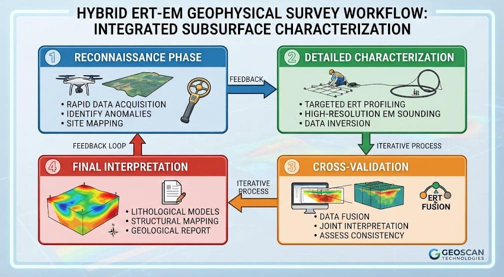
Many modern geoscience projects benefit from deploying electrical and electromagnetic methods together, offsetting each method’s inherent weaknesses. A standard industry workflow is described below:
1. Reconnaissance Phase
Run fast FDEM or TEM electromagnetic survey across full project area. Objective: identify major anomaly zones, regional conductivity trends, define priority detailed‑survey locations. This step reduces total project cost by avoiding dense high‑resolution profiling across the entire study area.
2. Detailed Characterization Phase
Deploy ERT / ERT‑IP profiles across high‑interest anomalies identified from EM reconnaissance. ERT fills TEM shallow blind‑zone gaps, delivers high‑resolution near‑surface structures, adds IP chargeability parameters for mineral or lithology discrimination.
3. Cross‑Validation & Joint‑Inversion
Compare resistivity models derived from ERT against conductivity models converted from EM datasets. Look for consistent subsurface patterns. Where model results conflict:
- Re‑examine field raw data for noise or acquisition errors.
- Review inversion parameter choices (regularization settings).
- Prioritize borehole verification at conflict locations.
Joint inversion workflows can incorporate both ERT and EM datasets to constrain unified subsurface property models and reduce interpretation ambiguity.
4. Final Interpretation Deliverable
Produce integrated geological interpretation document, clearly mark zones with high / moderate / low confidence levels, highlight data gaps caused by method limitations.
Ⅶ. Equipment Selection Considerations
When evaluating hardware for electrical versus electromagnetic geophysical surveys, project teams need to focus on application‑driven technical specifications rather than generic marketing parameters.
1. Electrical (ERT / IP) Instrument Key Specifications
- Transmitter maximum output current: Higher current improves depth performance for high‑resistivity terrain.
- Input impedance: Should exceed 50 MΩ for stable voltage reading under poor electrode‑contact conditions.
- Channel count and electrode switching capacity: Multi‑channel 60‑120 electrode systems accelerate 2‑D / 3‑D field acquisition.
- IP measurement capability: Chargeability sampling window support for mineral exploration projects.
- Noise‑rejection performance: Signal‑to‑noise ratio (SNR) metrics for urban EMI‑prone environments.
- Data‑output compatibility: Support for standard inversion software data formats.
Geotech Instrument’s electrical instrument series implements these specifications for near‑surface engineering, environmental and mineral exploration tasks.
2. Electromagnetic (TEM / FDEM) Instrument Key Specifications
For FDEM: usable frequency range, coil separation options, GNSS integration, real‑time conductivity output. For TEM: maximum transmitter moment, configurable pulse timing for early‑time (shallow) and late‑time (deep) data, receiver sampling rate, loop accessories.
Important practical note: TEM hardware cannot fix the physical shallow blind‑zone limitation, regardless of instrument performance specifications. This is fundamental physics rather than equipment defect.
Ⅷ. Common Pitfalls & Field‑Observed Failures
Field geophysicists frequently encounter predictable failure scenarios for both survey families. Awareness reduces costly mis‑interpretation:
- Electrical survey failure: bad electrode contact Dry, frozen or paved surfaces create high contact resistance. Voltage measurements become noisy or completely invalid. Mitigation: water electrodes, deploy contact‑improving soil media, relocate profile lines to soil‑covered locations.
- TEM blind‑zone misinterpretation Users mis‑trust TEM to resolve shallow 0‑20 m targets. Small voids, shallow contaminant layers may be invisible. Mitigation: supplement TEM with ERT or FDEM near‑surface data.
- EM interference from man‑made objects Power‑lines, metal fences, buried pipelines distort EM responses. Mitigation: site planning to avoid interference sources, apply digital noise filtering, cross‑validate with ERT datasets.
- Over‑interpreting geophysical models without ground truth Both electrical and EM inversion suffer non‑uniqueness: multiple different geological configurations can produce identical measured geophysical responses. Always recommend borehole calibration for high‑risk engineering or mining projectsASTM Inter….
Ⅸ. Conclusion
Electrical and electromagnetic geophysical survey techniques both map subsurface electrical properties, yet they serve distinct project needs.
Electrical surveys (ERT‑IP) excel for high‑resolution near‑surface imaging, support chargeability measurement, and resolve both resistive and conductive subsurface features. However they require reliable electrode‑ground galvanic contact and depth is bounded by array physical dimensions.
Electromagnetic surveys (FDEM / TEM) enable rapid non‑contact reconnaissance. TEM achieves great depth penetration but carries a physical shallow blind‑zone and works best for conductive subsurface targets.
Neither method universally outperforms the other. Optimal project outcomes frequently come from thoughtful combination: EM for wide‑area screening and depth extension, paired with electrical ERT‑IP for high‑resolution detailed characterization.
For your geophysical project planning, Geotech Instrument provides electrical, electromagnetic and complementary geophysical instruments and technical consultation for mineral, groundwater, environmental and engineering survey assignments. Contact our technical team to discuss your subsurface exploration requirements.
Reference Sources
Internal Knowledge Graph Link Collection
FAQ
Q1: What is the core difference between electrical and electromagnetic geophysical survey?
A: Electrical surveys inject electric current via ground electrodes and measure resistivity; electromagnetic surveys use magnetic‑field induction to detect subsurface conductivity without physical electrode contact. Electrical methods deliver excellent near‑surface resolution but require good soil‑electrode coupling. Electromagnetic methods work on frozen or paved ground, yet TEM systems have a 10‑20 m shallow blind‑zone. Many practical projects combine both approaches to offset individual‑method weaknesses.
Q2: Can electromagnetic survey replace ERT electrical survey for karst cavity detection?
A: Standalone electromagnetic (TEM) cannot fully replace ERT for karst cavity detection. TEM suffers from a shallow blind‑zone which hides near‑surface voids. ERT provides high‑resolution near‑surface imaging ideal for mapping karst conduits and cavities. TEM can complement ERT to explore deep bedrock structures below ERT depth limits. Best practice is combined ERT‑EM survey for karst site investigation.
Q3: Which survey should I select for sites with asphalt pavement or frozen soil?
A: Electromagnetic geophysical survey (FDEM or TEM) is preferred for asphalt‑covered or fully frozen sites. Electrical ERT requires galvanic electrode‑soil contact, which cannot be reliably achieved on pavement or frozen ground. Where small bare‑soil patches exist, limited supplementary ERT measurements can calibrate EM inversion results.
Q4: Why should I run hybrid ERT‑EM geophysical surveys instead of using only one single method?
A: Hybrid ERT‑EM survey compensates for each method’s physical limitations. Electromagnetic reconnaissance efficiently screens large‑area sites and reaches greater depth. ERT fills the TEM shallow blind‑zone and delivers high‑resolution near‑surface models, plus optional IP chargeability for mineral discrimination. Joint cross‑validation reduces geophysical inversion non‑uniqueness and improves overall interpretation confidence.
Q5: What are major noise sources for electrical and electromagnetic geophysical field work?
A: Primary noise for electrical surveys comes from poor electrode‑soil contact and natural telluric currents. For electromagnetic surveys, dominant noise sources are overhead power‑lines, metal fences, buried metallic utilities and coil misalignment. Field mitigation includes improved electrode watering for ERT, survey‑line routing away from metallic infrastructure, digital signal filtering, and cross‑comparison between ERT and EM datasets.