Welcome to Geotech!
-1.png)


How Does a Proton Magnetometer Work? From Proton Polarization to Magnetic Field Measurement
Overview:A Proton Magnetometer measures Earth’s total magnetic field by converting proton precession into a measurable frequency. The Proton Magnetometer Working Principle begins with proton polarization in a hydrogen-rich sensor, followed by free precession after the polarizing field is removed. The Proton Magnetometer Working Principle then uses the Larmor relationship to convert frequency into magnetic field intensity. A Proton Magnetometer therefore provides an absolute total-field measurement for professional magnetic surveys.
Ⅰ. What Is a Proton Magnetometer?
1. Definition
A proton magnetometer is a total-field magnetic instrument that determines magnetic field intensity from the precession frequency of protons in a hydrogen-rich sensor medium.
Unlike a vector magnetometer, which measures individual magnetic-field components, a proton precession instrument primarily provides the magnitude of the ambient magnetic field.
USGS describes proton magnetometers as instruments used to measure the total intensity of the magnetic field, while fluxgate magnetometers are commonly used for vector components.
2. Why the Measurement Is Based on Frequency
The key engineering advantage is the physical relationship between proton precession frequency and magnetic field strength.
For a proton precession magnetometer:
or:
where:
- f = proton precession frequency
- B = ambient magnetic field magnitude
- γp = proton gyromagnetic ratio
- ω = angular precession frequency
Because the gyromagnetic ratio is a physical constant, the measured frequency can be converted directly into magnetic field intensity.
USGS documentation gives the same fundamental relationship as:
and describes frequency counting as the basis for determining total magnetic field intensity.
Ⅱ. The Physics Behind Proton Precession
1. Hydrogen Protons Have Magnetic Moments
Hydrogen nuclei contain a single proton. A proton has intrinsic angular momentum, commonly described as spin, and this spin is associated with a magnetic moment.
When placed in a magnetic field, the proton magnetic moments do not simply point toward the field like small compass needles. Their collective behavior is governed by magnetic torque and angular momentum.
This produces a precessional motion around the magnetic-field direction.
2. Why Hydrogen-Rich Materials Are Used
A proton magnetometer requires a sensor medium containing a large number of hydrogen nuclei.
Depending on instrument design, the sensor may use a hydrogen-rich liquid such as water, alcohol, kerosene, or another suitable hydrocarbon-based medium.
The purpose is practical. More measurable proton magnetic moments can produce a stronger aggregate signal, which helps the electronics determine the precession frequency.
The exact sensor fluid, coil geometry, and electrical design depend on the instrument architecture.
3. The Sensor Is More Than a Container
The sensing assembly normally combines:
- A hydrogen-rich medium
- A polarization coil
- A signal pickup path
- Electrical connections
- Mechanical protection
- Temperature and environmental considerations
In some designs, the same coil can perform both polarization and signal detection.
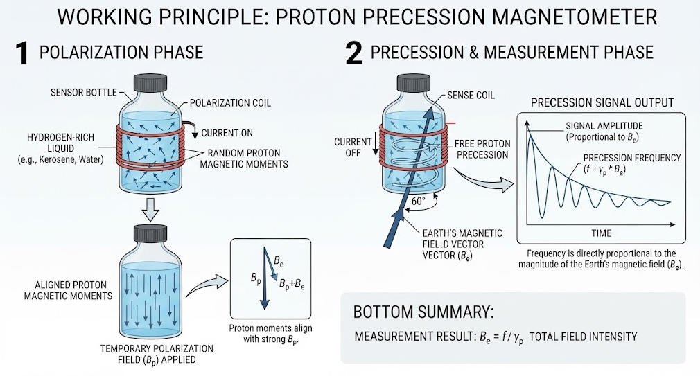
USGS documentation describes a coil surrounding a hydrogen-rich liquid, with the coil first used to polarize the protons and then to detect the induced precession signal.
Ⅲ. Proton Polarization: The First Measurement Stage
1. Applying a Polarizing Magnetic Field
The first stage is proton polarization.
A direct current is passed through the sensor coil. The current generates a temporary magnetic field that is much stronger than the ambient geomagnetic field.
The proton magnetic moments become partially aligned with this applied field.
This is not the final magnetic-field measurement. It is a preparation step that establishes a measurable initial proton polarization.
2. Why Polarization Is Necessary
The Earth’s magnetic field is relatively weak compared with the artificial polarization field generated inside the sensor.
Without controlled polarization, the net magnetic response from randomly distributed proton moments would be difficult to measure with the required signal-to-noise ratio.
Polarization therefore prepares the hydrogen-rich medium for the next stage.
3. Polarization Is a Dynamic Process
The polarization interval must be selected according to the sensor design and measurement sequence.
The objective is not simply to apply current for as long as possible.
The instrument must balance:
- Proton polarization level
- Measurement cycle time
- Power consumption
- Signal strength
- Sensor characteristics
- Required survey productivity
This becomes important when a magnetometer is used for closely spaced ground measurements.
Ⅳ. What Happens When the Polarizing Field Is Removed?
1. The Artificial Field Is Switched Off
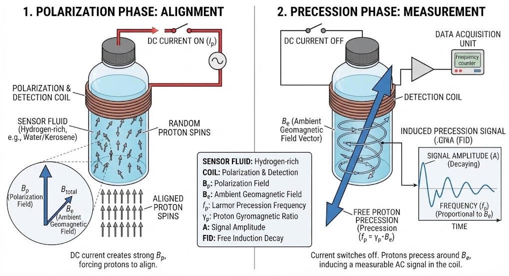
After the polarization stage, the current is rapidly removed.
The strong artificial magnetic field then collapses.
The proton ensemble is no longer dominated by the polarization field. Instead, it responds primarily to the ambient magnetic field at the measurement location.
This transition is fundamental to the operation of a free proton precession magnetometer.
2. Protons Begin Free Precession
The proton magnetic moments undergo free precession around the direction of the ambient magnetic field.
The precession frequency is proportional to the magnitude of that field.
This is the critical measurement event.
The instrument does not need to directly measure the magnetic field force itself. It measures the frequency generated by the proton precession and then calculates the field intensity.
USGS describes the process as polarization by a DC current followed by removal of the applied field, after which the protons precess around the Earth’s magnetic field.
3. Why This Is Called Proton Precession
The term proton precession magnetometer comes directly from this physical behavior.
The proton magnetic moment rotates around the local magnetic-field direction.
This motion is called precession.
The associated frequency is commonly referred to as the Larmor frequency.
Ⅴ. How Is the Proton Signal Detected?
1. Precession Produces a Weak Electrical Signal
As the proton magnetic moments precess, the changing magnetic flux through the sensing coil induces a small alternating electrical signal.
The signal is usually weak.
Therefore, the electronic system must extract a periodic component from noise and interference.
USGS field instrumentation documentation describes the induced signal as a small AC signal generated in the coil during proton precession.
2. Signal Conditioning
A typical measurement chain may include:
- Signal pickup
- Amplification
- Filtering
- Frequency detection
- Timing
- Frequency calculation
- Magnetic-field conversion
- Data storage
The exact signal-processing architecture differs between instruments.
The fundamental requirement remains the same: determine the proton precession frequency accurately.
3. Frequency Is More Important Than Signal Amplitude
For the basic proton-precession measurement, the field value is derived from frequency.
Therefore, signal amplitude and measurement frequency should not be treated as the same specification.
A strong signal can improve detection robustness, but the final field calculation depends primarily on accurately identifying the precession frequency.
Ⅵ. From Larmor Frequency to Magnetic Field
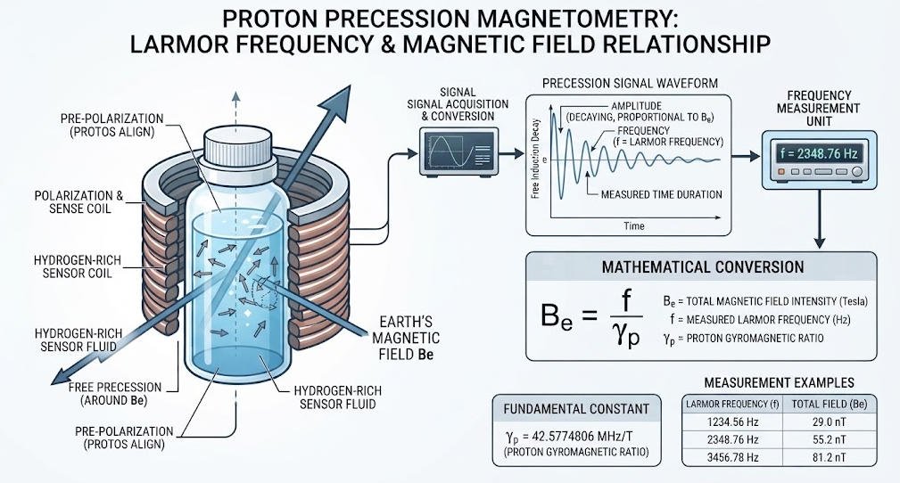
1. The Core Equation
The relationship can be written as:
Therefore:
The proportional relationship means that a higher magnetic field produces a higher proton precession frequency.
This direct physical relationship is the foundation of total-field proton magnetometry.
2. Example of the Frequency Relationship
For a geomagnetic field of approximately 50,000 nT, the proton precession frequency is on the order of 2.1 kHz.
The exact value depends on the local magnetic field.
This relationship explains why accurate timing and frequency measurement are central to the instrument’s performance.
3. What the Instrument Actually Reports
A proton precession magnetometer generally reports the total magnetic field intensity.
The total field can be represented as:
where:
- X = north component
- Y = east component
- Z = vertical component
- F = total magnetic-field intensity
USGS uses this formulation when describing absolute total-field measurements at geomagnetic observatories.
Ⅶ. Total Field vs Vector Magnetic Measurement
1. Proton Magnetometer Measures a Scalar Quantity
A proton precession magnetometer primarily provides the magnitude of the magnetic field.
It does not directly provide the complete directional vector.
This distinction matters when selecting equipment for a survey.
2. Fluxgate Magnetometer Measures Components
A triaxial fluxgate system can measure vector components and derive quantities such as:
- Horizontal intensity
- Vertical intensity
- Declination
- Field direction
USGS observatories commonly use a fluxgate magnetometer for vector data and a proton magnetometer for absolute total-field intensity.
3. Engineering Selection
| Requirement | Proton Precession Magnetometer | Vector Fluxgate Magnetometer |
|---|---|---|
| Total field | Strong fit | Can be derived |
| Field direction | Not primary output | Direct measurement |
| Absolute total-field reference | Strong fit | Usually requires reference/calibration |
| Ground magnetic surveying | Common application | Also applicable |
| Observatory use | Absolute F measurement | Continuous vector monitoring |
| Sensor orientation | Less critical for scalar magnitude | More important |
The correct choice depends on the survey objective rather than the assumption that one technology replaces the other.
Ⅷ. What Does a Proton Magnetometer Measure in Geological Exploration?
1. Magnetic Field Anomalies
A magnetic survey measures spatial variations in the Earth’s magnetic field.
These variations can be associated with differences in:
- Magnetic susceptibility
- Remanent magnetization
- Lithology
- Mineral composition
- Geological structure
- Buried ferrous objects
The magnetometer does not directly identify a mineral deposit.
It measures a magnetic response that must be interpreted using geology and other geophysical information.
The US EPA notes that magnetic surveys can reveal subsurface ferrous objects and support geological mapping, but also emphasizes the value of combining magnetic data with complementary methods.
2. Mineral Exploration
Magnetic data can help map magnetic lithologies and structures.
In mineral exploration, the usefulness of the response depends on the magnetic properties of the target and host rocks.
Therefore, survey design should consider:
- Expected magnetic susceptibility contrast
- Target depth
- Target geometry
- Background magnetic field
- Survey line spacing
- Sensor height
- Cultural interference
3. Engineering and Environmental Surveys
Ground magnetic surveys can also locate or map:
- Buried ferrous pipelines
- Storage tanks
- Abandoned wells
- Metallic infrastructure
- Landfill-related ferrous material
- Other magnetic targets
EPA technical documentation describes total-field measurements and gradient measurements using proton magnetometers for buried-target investigations.
4. Archaeological Surveys
Magnetic anomalies can also indicate archaeological features where buried materials or disturbed soils produce measurable magnetic contrasts.
However, detection depends on target size, magnetic contrast, depth, soil conditions, cultural noise, and survey spacing.
A proton magnetometer therefore provides measurement data, not an automatic archaeological interpretation.
Ⅸ. Why Survey Environment Matters
1. Cultural Magnetic Noise
A proton magnetometer can measure extremely small field variations.
That sensitivity also means the survey may be affected by nearby magnetic sources.
Examples include:
- Vehicles
- Steel fences
- Power infrastructure
- Machinery
- Reinforced concrete
- Buried pipelines
- Personal metal objects
Field procedures should minimize unnecessary magnetic interference.
2. Sensor Position Matters
The sensor should be positioned away from strongly magnetic equipment whenever possible.
Vehicle-mounted surveys often use a boom to place the sensor away from the vehicle.
USGS field mapping has used vehicle-mounted proton precession magnetometers with the sensor physically separated from the vehicle to reduce magnetic contamination.
3. Survey Repeatability
Repeatable sensor height, line spacing, walking speed, station timing, and positioning improve the comparability of measurements.
For detailed anomaly mapping, acquisition consistency can be as important as nominal instrument resolution.
Ⅹ. Measurement Cycle of a Proton Magnetometer
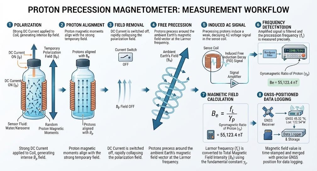
The complete process can be summarized as follows.
1. Step-by-Step Workflow
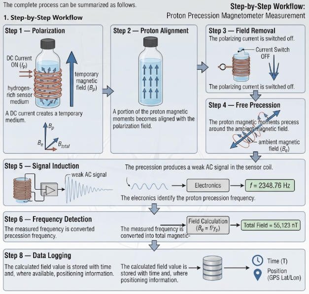
This sequence is consistent with the fundamental free-proton-precession measurement mechanism documented by USGS.
Ⅺ. What Specifications Matter When Selecting a Proton Magnetometer?
A specification sheet should be evaluated as a complete measurement system.
1. Sensitivity
Sensitivity indicates the smallest magnetic-field variation the instrument can meaningfully detect under specified conditions.
Higher sensitivity can be valuable when the expected anomaly is weak.
However, field sensitivity should not be interpreted independently of environmental noise and survey methodology.
2. Resolution
Resolution describes the smallest numerical increment that the system can represent.
Resolution and sensitivity are related but are not interchangeable.
A display capable of showing 0.01 nT does not automatically mean that every 0.01 nT geological variation can be reliably detected in the field.
3. Accuracy
Accuracy concerns how close the measured value is to the true or accepted value.
For engineering decisions, users should distinguish:
- Resolution
- Sensitivity
- Repeatability
- Absolute accuracy
- Stability
These specifications describe different performance characteristics.
4. Sampling Interval
Sampling interval determines how frequently the system produces measurements.
For moving surveys, a shorter interval can provide greater spatial sampling density.
For stationary monitoring, the appropriate interval depends on the temporal variation being investigated.
5. Dynamic Range
The measurement range must cover the expected local geomagnetic field.
A suitable instrument should operate comfortably within its specified range under the survey area’s expected magnetic conditions.
6. Gradient Capability
For magnetic gradient work, two sensors can measure the field at different positions.
The difference between their measurements can provide gradient information.
EPA documentation describes both two-point total-field gradient measurements and dual-sensor gradiometer configurations.
| Specification | What It Means | Why It Matters |
|---|---|---|
| Sensitivity | Ability to detect small field changes | Weak anomaly detection |
| Resolution | Smallest displayed/measurable increment | Data granularity |
| Accuracy | Closeness to reference value | Absolute field measurement |
| Sampling interval | Time between readings | Spatial/temporal density |
| Dynamic range | Supported field range | Regional compatibility |
| Gradient capability | Difference between sensor positions | Near-surface anomaly mapping |
| Temperature range | Operating environmental range | Field deployment |
| Timing/GNSS | Measurement time and position | Survey integration |
Ⅻ. Why Frequency Stability Matters
1. The Measurement Is Time-Based
Because magnetic-field intensity is calculated from precession frequency, timing stability directly affects measurement quality.
The electronics must distinguish the periodic proton signal from noise and determine its frequency reliably.
2. Oscillator Stability
The instrument’s internal timing reference can influence frequency measurement.
A stable oscillator can improve the repeatability of frequency determination.
This is why high-quality proton magnetometers may use temperature-stable frequency references.
3. Do Not Confuse Clock Stability With Sensor Accuracy
A high-stability oscillator does not automatically guarantee high overall field accuracy.
The complete measurement chain also includes:
- Sensor characteristics
- Coil geometry
- Signal amplitude
- Electronic noise
- Frequency extraction
- Temperature effects
- External magnetic interference
- Positioning
- Survey procedure
Engineering performance must therefore be evaluated at the system level.
ⅩⅢ. Proton Magnetometer vs Other Magnetic Technologies
| Technology | Primary Measurement | Typical Strength | Important Consideration |
|---|---|---|---|
| Proton Precession | Total magnetic field | Absolute total-field measurement | Lower cycle-rate potential than some modern technologies |
| Overhauser | Total magnetic field | Faster measurement and high sensitivity | More complex technology |
| Fluxgate | Vector components | Directional and continuous measurement | Orientation and calibration matter |
| Cesium Vapor | Total field | Fast sampling and high sensitivity | More specialized electronics |
| Other OPM technologies | Total/vector depending on design | Very high sensitivity potential | Application and system complexity |
The comparison should not be reduced to a simple “better or worse” ranking.
Survey objectives determine which technology is appropriate.
For example, an absolute total-field measurement and a continuous vector measurement are different engineering requirements.
ⅩⅣ. Proton Magnetometer Applications
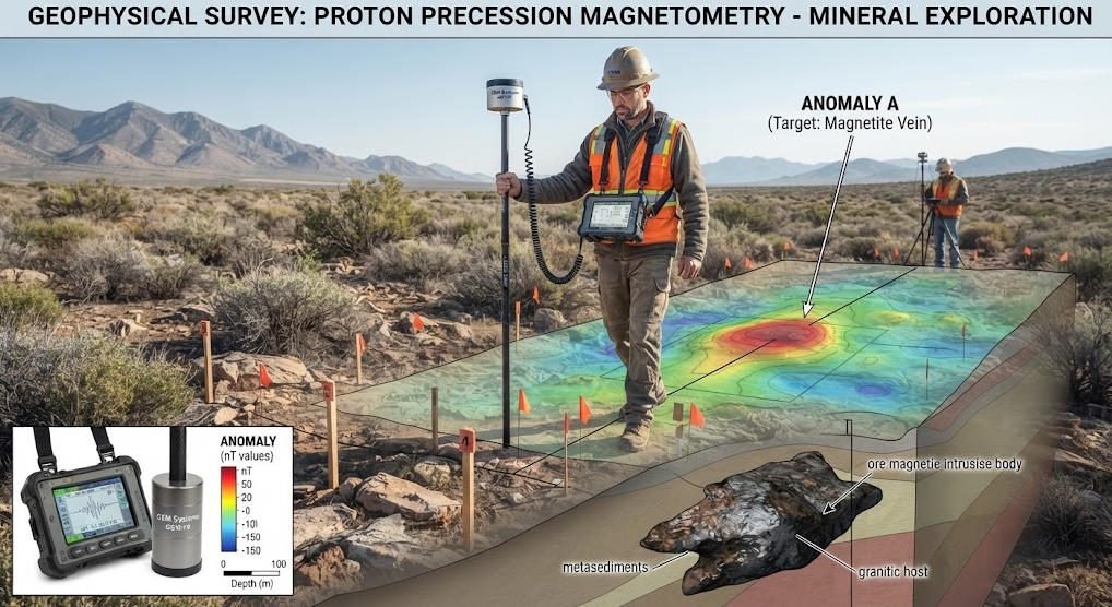
1. Mineral Exploration
Magnetic surveys can help map magnetic rock units, structural boundaries and magnetic mineralization.
The method is especially useful when there is sufficient magnetic contrast between the target and surrounding geology.
2. Geological Mapping
Closely spaced total-field measurements can reveal spatial magnetic patterns.
These patterns may support geological interpretation and structural mapping.
USGS mapping work has demonstrated the use of near-ground total-intensity magnetic data for geological modeling and lithologic discrimination.
3. Archaeology
Magnetic surveys can detect anomalies caused by buried structures, fired materials, ferrous objects, and disturbed ground.
The actual response depends strongly on archaeological context and target properties.
4. Engineering Investigation
Magnetic measurements can support the investigation of buried metallic infrastructure and other magnetic targets.
The method can be particularly useful where the target produces a clear magnetic contrast against the surrounding environment.
5. Geomagnetic Monitoring
Proton magnetometers have also been used for long-term monitoring of changes in total magnetic-field intensity.
USGS research describes proton precession magnetometers sampling total magnetic-field intensity at 0.1 or 0.25 nT resolution in monitoring networks.
ⅩⅤ. How to Improve Proton Magnetometer Data Quality
1. Establish a Magnetically Quiet Survey Procedure
Before acquisition, identify nearby magnetic interference sources.
Keep vehicles, tools and other ferrous objects away from the sensor whenever practical.
2. Maintain Consistent Sensor Geometry
Keep sensor height and orientation consistent within the survey design.
This is especially important when interpreting small spatial anomalies.
3. Use Base-Station Monitoring When Required
The Earth’s magnetic field changes with time.
A base station can record temporal variation and support diurnal correction of mobile survey data.
Historical USGS magnetic surveys have used automatically recording base stations to correct diurnal variations.
4. Integrate Positioning Data
GNSS positioning allows magnetic measurements to be associated with precise survey locations.
This improves line control, gridding, mapping, and repeat surveys.
5. Combine Complementary Geophysical Methods
Magnetic data can identify magnetic contrasts, but it does not directly determine resistivity, dielectric properties, seismic velocity, or chargeability.
Depending on the geological objective, magnetic surveying can therefore be integrated with:
- ERT
- IP
- VES
- GPR
- Seismic
- Electromagnetic methods
EPA explicitly recommends combining magnetic surveys with complementary methods where different physical properties are needed for interpretation.
ⅩⅥ. Common Technical Misunderstandings
1. “Higher Resolution Means Higher Accuracy”
Not necessarily.
Resolution describes measurement increments, while accuracy describes agreement with a reference value.
A system can have fine numerical resolution without equivalent absolute accuracy.
2. “The Proton Magnetometer Measures the Ore Body Directly”
It does not.
The instrument measures magnetic-field intensity.
Geologists infer geological sources from the spatial pattern of magnetic anomalies.
3. “Every Magnetic Anomaly Indicates Mineralization”
Not necessarily.
Magnetic anomalies can originate from natural geology, infrastructure, buried ferrous objects, cultural materials, or other sources.
Interpretation requires geological context.
4. “The Sensor Must Always Be Perfectly Level”
A total-field instrument primarily measures field magnitude rather than one directional component.
This generally makes precise leveling less critical than for vector measurements.
However, sensor geometry and environmental interference can still influence practical data quality.
ⅩⅦ. Geotech JPMG Proton Magnetometer
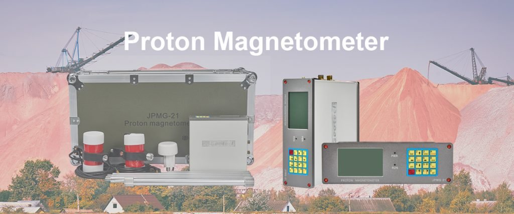
Geotech’s JPMG proton magnetometer product family is designed for field geomagnetic survey applications, including mineral exploration, buried magnetic-target detection, archaeological investigation and engineering surveys. The current Geotech product page identifies the JPMG family as a dual-sensor proton magnetometer system.
1. Field-Oriented Measurement Architecture
The JPMG system combines a field sensor with a dedicated control and acquisition unit.
This type of architecture is intended to support repeated measurements in practical field environments rather than laboratory-only magnetic measurements.
2. Single-Sensor and Dual-Sensor Configurations
Geotech provides both single-sensor and dual-sensor proton magnetometer configurations.
The single-sensor configuration is suitable for conventional total-field magnetic surveying, while dual-sensor configurations can support gradient-oriented workflows where field differences between sensor positions are important.
3. Field Applications
Depending on geological and site conditions, potential applications include:
- Mineral prospecting
- Magnetic geological mapping
- Archaeological investigation
- Buried ferrous target detection
- Engineering geophysics
- Abandoned well investigation
- Magnetic gradient surveying
The appropriate configuration should be selected according to target size, expected anomaly amplitude, survey geometry, required sampling density and environmental interference.
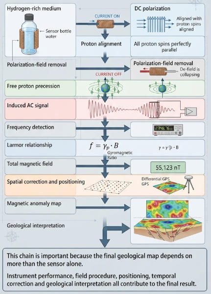
ⅩⅧ. From Proton Polarization to a Geological Anomaly Map
The complete engineering chain can be expressed as:
ⅩⅨ. Key Takeaways for Geophysical Engineers
A proton magnetometer is fundamentally a frequency-based total-field magnetic measurement system.
Its operating sequence is straightforward:
- Polarize hydrogen protons with a temporary magnetic field.
- Remove the polarization field.
- Allow the protons to undergo free precession.
- Detect the induced electrical signal.
- Determine the precession frequency.
- Convert frequency into magnetic-field intensity.
- Associate the measurement with time and position.
- Interpret spatial variations as magnetic anomalies.
The underlying physics is well established.
The practical challenge is achieving reliable measurements under real field conditions.
For professional survey work, engineers should therefore evaluate the entire measurement chain rather than focusing on a single specification such as nominal sensitivity or display resolution.
ⅩⅩ. Conclusion
The proton magnetometer works because proton precession provides a direct physical link between magnetic-field intensity and measurable frequency.
The core process is proton polarization → free precession → signal detection → frequency measurement → magnetic-field calculation.
This mechanism makes proton precession magnetometers useful for total-field magnetic surveying, geological mapping, mineral exploration, archaeological investigation, engineering surveys and geomagnetic monitoring.
The quality of the final result depends not only on the sensor. Survey geometry, magnetic interference, temperature, timing, sampling strategy, positioning and data correction must also be controlled.
For this reason, selecting a proton magnetometer should begin with the survey objective and expected geological signal, then proceed to the instrument’s measurement architecture and field specifications.
Related Articles
| Title | Core Content | URL |
|---|---|---|
| Proton Magnetometer: How Proton Precession Works | Explains proton precession, Larmor frequency and magnetic-field calculation. | https://geotechcn.net/service/how-proton-precession-works-in-measurement/ |
| Proton Precession Magnetometer | Introduces proton precession magnetometer technology and its measurement mechanism. | https://geotechcn.net/service/proton-precession-magnetometer-3/ |
| Proton Magnetometer Signal Processing | Covers amplification, filtering and extraction of weak proton-precession signals. | https://geotechcn.net/service/proton-magnetometer-signal-processing/ |
| How Stable Is Your Proton Magnetometer? | Discusses stability, environmental effects and temperature-related measurement factors. | https://geotechcn.net/service/proton-magnetometer-stability/ |
| Proton Magnetometer Signal Modulation Due to Rotation | Examines rotation-related signal effects in dynamic magnetic surveys. | https://geotechcn.net/service/modulation-of-a-proton-magnetometer-signal-due-to-rotation/ |
| Proton Magnetometer | Dual-sensor JPMG product and field deployment information. | https://geotechcn.net/products/magnetic-instrument/dual-sensor-proton-magnetometer/ |
| Proton Magnetometer | Single-sensor JPMG configuration and applications. | https://geotechcn.net/products/magnetic-instrument/proton-magnetometer-single/ |
Reference Sources
| Title | Core Content | URL |
|---|---|---|
| Introduction to Geomagnetism — USGS | Explains total magnetic-field intensity, proton precession magnetometers and vector magnetic measurements. | https://www.usgs.gov/programs/geomagnetism/introduction-geomagnetism |
| Instrumentation — USGS Geomagnetism Program | Describes the use of proton magnetometers for total-field measurements and fluxgates for vector data. | https://www.usgs.gov/programs/geomagnetism/science/instrumentation |
| Proton Magnetometer Technical Report — USGS | Provides the proton precession equation, polarization mechanism and frequency-based field calculation. | https://pubs.usgs.gov/of/1981/1346/report.pdf |
| Magnetic Method — U.S. EPA | Explains magnetic survey applications, total-field measurements and integration with complementary geophysical methods. | https://www.epa.gov/environmental-geophysics/magnetic-method |
| Review of Magnetic Field Monitoring — USGS | Documents proton precession magnetometer use for long-term total-field monitoring and nT-scale measurements. | https://www.usgs.gov/publications/review-magnetic-field-monitoring-near-active-faults-and-volcanic-calderas-california |
FAQ
Q1. How does a proton magnetometer measure magnetic field intensity?
A proton magnetometer measures magnetic field intensity by detecting the precession frequency of protons in a hydrogen-rich sensor. A temporary polarization field aligns the protons, then the field is removed. The resulting free-precession frequency is proportional to the ambient magnetic-field magnitude and is converted into a total-field value.
Q2. What is proton precession in a magnetometer?
Proton precession is the rotational motion of proton magnetic moments around the direction of an ambient magnetic field. After the artificial polarization field is removed, the protons undergo free precession at the Larmor frequency. Measuring this frequency allows the instrument to determine the magnitude of the surrounding magnetic field.
Q3. Does a proton magnetometer measure total magnetic field or magnetic-field direction?
A conventional proton precession magnetometer primarily measures total magnetic-field intensity rather than individual vector components. The total field can be expressed as (F=\sqrt{X^2+Y^2+Z^2}). Vector components require an appropriate vector magnetometer, such as a triaxial fluxgate system.
Q4. What affects proton magnetometer measurement accuracy in the field?
Accuracy depends on more than nominal sensor specifications. External magnetic interference, sensor position, temperature, signal quality, frequency measurement, timing stability, sampling strategy and survey repeatability can all affect results. Depending on the survey environment, base-station correction and complementary geophysical data may also be required.
Q5. Where are proton magnetometers used?
Proton magnetometers are used for total-field magnetic surveying in mineral exploration, geological mapping, archaeological investigation, engineering surveys and geomagnetic monitoring. Their usefulness depends on magnetic contrast between the target and surrounding materials, survey geometry, target depth, environmental interference and the quality of the acquisition and interpretation workflow.