Welcome to Geotech!
-1.png)


Which is the best Electromagnetic Geophysical Survey Provider?
Overview:This practical framework supports informed EM Survey Provider Selection for mineral, environmental and infrastructure projects. It outlines evaluation criteria for every Electromagnetic Geophysical Survey, from method justification to QA/QC, and defines how to align Electromagnetic Geophysical Survey scope with project objectives through rigorous EM Survey Provider Selection processes.
Ⅰ. What Does an Electromagnetic Geophysical Survey Provider Do?
1. Core Definition & Scope of Services
An electromagnetic geophysical survey provider is a company or technical team that designs, acquires, processes, interprets and reports electromagnetic measurements to characterize subsurface electrical properties. Full-service providers deliver end-to-end solutions spanning survey design, method selection, equipment deployment, field acquisition, positioning, QA/QC, data processing, inversion, geological interpretation, mapping, technical reporting and follow-up recommendations.
A critical distinction separates survey providers from equipment suppliers. An equipment supplier only sells or rents hardware. A survey provider assumes full responsibility for converting raw field measurements into decision-ready technical products. This distinction is the most important factor in procurement planning.
2. Why Provider Capability Directly Impacts Results
Electromagnetic methods measure physical responses, not direct geological labels. The US EPA defines surface EM methods as techniques that induce electromagnetic energy into the subsurface and measure the response of earth materials. Conductivity, magnetic susceptibility and related electromagnetic properties all influence the measured response.
An EM anomaly does not automatically indicate groundwater, mineralization, contamination, a cavity, a buried pipeline or a geological boundary. Interpretation depends on physical contrast, survey configuration, data quality and geological context. A qualified provider must understand this full chain of inference.
Ⅱ. Start With the Geological Objective
1. Define Targets Before Evaluating Providers
Before contacting contractors, define what you need to investigate in geological terms. Matching the target to the method is the foundation of a successful survey.
| Project Objective | Possible EM Target | Key Technical Question |
|---|---|---|
| Groundwater mapping | Conductive aquifer, saline interface | What electrical contrast should be expected? |
| Mineral exploration | Conductive mineralization | Is the target sufficiently conductive and large? |
| Environmental investigation | Conductive plume or buried infrastructure | Can the anomaly be separated from cultural noise? |
| Civil engineering | Conductive or resistive structure | What scale and depth must be resolved? |
| Utility investigation | Buried conductive target | Is EM appropriate for the target and site? |
| Regional exploration | Large-scale conductivity structure | Is airborne or deep EM justified? |
ASTM D6429 states that a geophysical method requires a meaningful physical-property contrast between the target and background. If that contrast is weak, the method may not reliably detect the target regardless of equipment quality. Defining this contrast first lets you evaluate providers on technical merit, not marketing.
2. Require Physical Basis Explanations in Proposals
A technically strong proposal follows a clear logical chain: Target → Expected physical contrast → EM response → Acquisition method → Interpretation
A weak proposal may simply state: “Our EM system can detect groundwater.” A strong proposal explains what electrical-property contrast is expected, what geological conditions could produce the same response, and how the survey will distinguish competing interpretations. This ability to connect physics to geology is a primary provider-selection criterion.
Ⅲ. Verify EM Method Expertise
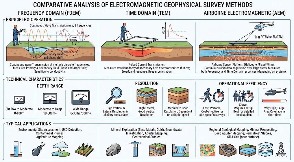
There is no universal electromagnetic survey method. Different methods operate with distinct source configurations, frequencies, time windows, spatial sampling, depth sensitivity and noise characteristics. The US EPA identifies major surface EM families including Frequency Domain Electromagnetics (FDEM), Time Domain Electromagnetics (TDEM), GPR and VLF methods.
1. Frequency-Domain Electromagnetics (FDEM)
FDEM uses continuous electromagnetic excitation at selected frequencies. It is most useful for rapid conductivity mapping and near-surface investigations.
A qualified provider should be able to explain:
- Operating frequency and coil geometry
- Coil separation and orientation
- Apparent conductivity output methodology
- Positioning and cultural-noise risks
- Expected investigation sensitivity for the target
Do not accept a proposal that selects FDEM simply because it is fast. The method must be justified against the specific target and site conditions.
2. Time-Domain Electromagnetics (TDEM/TEM)
TDEM or TEM uses a transient source and records the decay response after transmitter current changes. Time-domain measurements extract information from different stages of the transient response.
A competent provider should explain:
- Transmitter configuration and loop geometry
- Current waveform and receiver configuration
- Time channel setup and noise floor
- Late-time data quality controls
- Inversion strategy and modeling approach
The key issue is not merely whether the contractor owns a TEM system. The issue is whether the system and survey design can produce useful data under the site’s expected electrical and logistical conditions.
3. VLF & Controlled-Source Methods
VLF uses remote radio transmitters as the primary electromagnetic source. It can be useful for mapping conductive structures such as fractures and faults in appropriate geological settings. However, signal quality depends on transmitter availability and orientation. A provider should discuss those limitations rather than presenting VLF as a universal deep exploration method.
Controlled-source audio-frequency magnetotellurics (CSAMT) and magnetotellurics (MT) address different exploration scales than most near-surface EM systems. They may be considered for deeper geological investigations including geothermal, groundwater, mineral and regional structural studies. The provider should demonstrate experience with source-receiver geometry, field measurements, frequency selection and impedance analysis.
4. Airborne EM Survey Capabilities
Airborne EM provides large-area coverage efficiently. The USGS notes that electromagnetic surveys can be conducted from air or ground and used to create resistivity-related maps for geological interpretation.
Airborne systems may be appropriate when:
- The survey area is large
- Ground access is difficult
- Regional conductivity mapping is required
- Rapid spatial coverage is a priority
Airborne EM introduces additional requirements including navigation, height control, sensor geometry, flight-line spacing, tie lines, positioning, terrain clearance, calibration and platform-specific noise. A provider without airborne-specific QA/QC experience should not be treated as equivalent to an experienced AEM contractor.
Ⅳ. Evaluate Technical Experience, Not Marketing Claims
1. Prioritize Relevant Project Experience
The relevant question is not “How many years has your company operated?” The correct question is “How many projects similar to mine has the technical team completed?”
Relevant experience should match:
- Geological environment and target type
- Survey scale and EM method
- Terrain and environmental conditions
- Required depth and final deliverables
A provider experienced in shallow environmental FDEM may not automatically be qualified for deep mineral-exploration TEM. Likewise, an airborne EM contractor may not be the right choice for a small urban engineering investigation.
2. Review the Technical Team Composition
Ask for the roles and responsibilities of:
- Project manager
- Lead geophysicist
- Field supervisor
- Data processor
- Inversion specialist
- Geological interpreter
The person responsible for final interpretation matters as much as the field crew. ASTM specifically identifies the competence of personnel responsible for planning, conducting and interpreting surveys as a major factor in successful geophysical investigation.
3. Audit Sample Technical Reports
A good sample report should demonstrate more than attractive color maps. Look for:
- Survey objectives and site description
- Method selection rationale
- Equipment description and acquisition parameters
- Survey layout and coordinate system
- QA/QC methodology and results
- Data-processing workflow and inversion methodology
- Uncertainty and limitations discussion
- Geological interpretation with supporting evidence
- Actionable recommendations
A report that only contains a conductivity map may be visually impressive but technically incomplete.
Ⅴ. Assess the Proposed Survey Design
A professional provider should submit a detailed survey design before field deployment.
1. Survey Geometry & Layout
The proposal should identify:
- Survey lines and station spacing
- Line spacing and survey orientation
- Area coverage and control points
- Tie lines where appropriate
- Terrain considerations and access routes
ASTM D6429 notes that linear transects may be suitable for linear features, while multiple transects or 3D survey geometries may be required for areal trends and nonlinear targets.
2. Spatial Sampling Density
More data does not automatically mean better data. Sampling density must match the expected target size. If the target is small but line spacing is too large, the anomaly may be missed. If the target is large and the survey is excessively dense, the project may incur unnecessary acquisition and processing costs.
A strong provider should explain why the proposed spatial sampling is appropriate for the target. The justification should reference target size, depth and expected contrast.
3. Actual Survey Coverage Scope
Ask: “How much of the site will actually be measured?” A low-cost proposal may reduce survey coverage while keeping the same-looking headline price.
Compare on an equal basis:
- Total survey area
- Line kilometers and station count
- Line spacing and station density
- Tie-line coverage percentage
- Repeat measurement percentage
Total acquisition scope matters more than the daily rate alone.
Ⅵ. Evaluate Equipment & Instrument Configuration
Equipment matters, but equipment alone does not define technical quality.
1. Verify Full Instrument Specifications
Ask for:
- Manufacturer and model
- Sensor configuration and transmitter type
- Receiver type and frequency/time-window range
- Positioning system and data logging capability
- Calibration status and traceability
Avoid evaluating instruments only by brand reputation. The same platform may perform differently depending on configuration and field conditions.
2. Align Configuration to Survey Objectives
A provider proposing FDEM should explain why the selected frequency and coil geometry fit the target. A TEM provider should explain why the transmitter loop and time gates are suitable. An AEM provider should explain flight altitude, line spacing, sensor configuration and expected noise levels.
A technical proposal should connect instrument configuration directly to geological objectives. Generic equipment lists without justification are a warning sign.
3. Avoid Overreliance on “Maximum Depth” Claims
One of the most common procurement mistakes is comparing providers using a single maximum-depth number.
Actual detectability depends on:
- Conductivity structure and target size
- Target depth and signal strength
- Frequency and time window
- Noise level and survey geometry
- Processing and inversion quality
- Environmental conditions
The maximum theoretical depth of a system is not equivalent to reliable target detection depth. Always ask for project-specific evidence of detectability.
Ⅶ. Mandate Formal QA/QC in Contracts
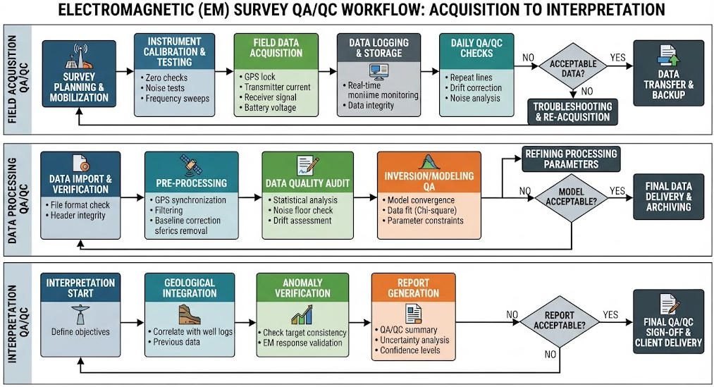
QA/QC should not be treated as a final reporting formality. It should operate throughout the entire project lifecycle.
1. Field QA/QC Protocols
A provider should have documented procedures for:
- Instrument checks and calibration
- Background measurements and position verification
- Repeat station measurement
- Noise monitoring and data completeness
- Equipment drift tracking
- Daily field review and sign-off
2. Processing Quality Controls
Processing should include checks for:
- Spikes and dropouts
- Position errors and sensor drift
- Cultural interference
- Inconsistent line responses
- Poor signal-to-noise sections
For large EM surveys, line-to-line consistency and positioning can be critical. Publicly documented airborne EM projects show QA/QC procedures include line-to-line checks, tie-line leveling, positioning review, EM system-response checks and noise assessment.
3. Interpretation Quality Assurance
The provider should distinguish between: Measured data → Processed data → Inverted model → Geological interpretation
These are not the same thing. The final interpretation should identify which conclusions are directly supported by measurements and which depend on geological assumptions.
Ⅷ. Assess Data Processing & Inversion Capabilities
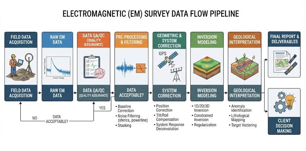
1. Map the Full Data Pipeline
A provider should be able to explain the complete data pipeline: Raw EM Signal → Quality Control → Filtering / Correction → Positioning → Apparent Conductivity / Decay Data → Inversion → Conductivity/Resistivity Model → Geological Interpretation → Final Maps and Report
A provider that cannot explain this chain clearly may not be suitable for technically demanding projects.
2. Evaluate Inversion Methodology
Different geological models can produce similar EM responses. This is a fundamental issue in geophysical interpretation.
The provider should explain:
- Whether 1D, 2D or 3D inversion is proposed
- What assumptions are used in the model
- How topography is handled
- How data errors are incorporated
- How model regularization is selected
- How sensitivity is assessed
- How non-uniqueness is addressed
USGS research continues to emphasize computational EM methods and inversion as important components of modern groundwater and subsurface EM interpretation.
3. Require Reusable Data Deliverables
Do not accept a final PDF as the only deliverable.
Depending on the project, request:
- Raw field data
- Processed data products
- Coordinate files and line metadata
- Inversion model files
- GIS layers, grids and sections
- Final technical report
This allows future reinterpretation and reduces long-term dependence on a single contractor.
Ⅸ. Use a Technical Comparison Matrix
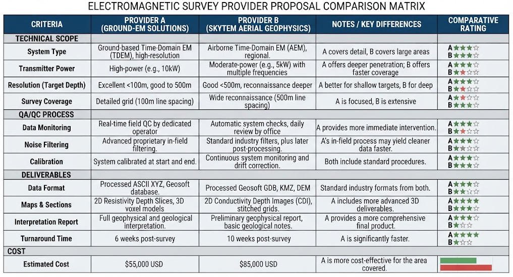
A structured matrix is more reliable than comparing company websites.
| Evaluation Category | Key Questions | Evidence to Request |
|---|---|---|
| Method expertise | Can the provider justify the selected EM method? | Technical proposal, method statement |
| Geological expertise | Does the team understand the target geology? | Team CVs, project examples |
| Field capability | Can the team operate in the actual terrain? | Field methodology, safety plan |
| Equipment | Is the configuration appropriate for the target? | Equipment list, specifications |
| Survey design | Is sampling sufficient and justified? | Survey layout, spacing rationale |
| QA/QC | How will data quality be verified? | QA/QC plan, procedures |
| Processing | How will raw data be corrected? | Processing workflow description |
| Inversion | What model will be generated? | Sample inversion output |
| Interpretation | Can the provider connect EM response to geology? | Sample technical report |
| Deliverables | Are raw and processed datasets included? | Deliverable schedule |
| Schedule | Is the timeline technically realistic? | Project milestone plan |
1. Weight Technical Fit Over Headline Price
The cheapest quotation may not have the lowest total project cost. A technically inadequate survey can lead to repeat fieldwork, additional drilling, delayed decisions, misinterpretation, unusable data and additional processing.
The purpose of procurement is not to minimize the quotation alone. It is to obtain the required information with acceptable technical and project risk.
2. Side-by-Side Proposal Comparison Framework
Suppose two contractors submit proposals. Provider A offers a lower daily rate, basic acquisition, limited interpretation and no detailed QA/QC. Provider B offers a higher daily rate, target-specific design, field QA/QC, inversion, geological interpretation and full data delivery.
The correct evaluation should not ask “Which daily rate is lower?” Instead compare the complete scope of work.
| Proposal Element | Provider A | Provider B |
|---|---|---|
| Method justification | Limited | Detailed |
| Target analysis | Basic | Project-specific |
| Survey design | Standard | Customized |
| Field QA/QC | Unclear | Defined |
| Processing workflow | Basic | Documented |
| Inversion methodology | Limited | Defined |
| Geological interpretation | Limited | Included |
| Raw data delivery | Confirm only | Included |
| GIS deliverables | Confirm only | Defined |
| Technical report | Short | Detailed |
| Follow-up support | Confirm only | Defined |
This approach turns a quotation comparison into a technical procurement review.
Ⅹ. Common Red Flags to Avoid
- Guaranteed detection claims – Be cautious when a provider guarantees EM will find groundwater, identify a specific ore body, locate every buried object or determine exact depth. Geophysical methods require measurable physical contrast, and success depends on site conditions.
- One method for every project – A provider that recommends the same EM method for every site should be questioned. The method must respond to target geometry, depth, conductivity, survey scale, access, noise and geology.
- Excessive maximum depth marketing – Maximum theoretical investigation depth is not equivalent to reliable target detection. Ask for project-specific evidence instead.
- No raw data delivery – A final interpretation without access to underlying data creates long-term dependency. Ask what data will be delivered and in what format.
- No discussion of noise – If a proposal discusses equipment but never discusses power lines, buried metal, fences, buildings, cultural interference or signal-to-noise ratio, the technical assessment may be incomplete.
- No limitations section – A credible technical report explains limitations. Professional interpretation should identify uncertainty rather than hide it.
Ⅺ. What to Include in an EM Survey RFP
A good Request for Proposal should define the project technically before requesting price.
- Project background – Include site location, geological setting, existing investigation data, project purpose and target type.
- Survey objective – Define what the contractor must investigate. For example: “Map lateral and vertical conductivity variations associated with suspected groundwater-bearing structures within the defined survey area.” This is better than simply requesting “Perform an EM survey.”
- Required technical scope – Specify proposed method, survey area, line spacing, station spacing, positioning, expected depth range, data processing, inversion, interpretation and QA/QC requirements. Allow technically qualified providers to propose modifications where justified.
- Required deliverables – Specify whether the contractor must provide raw data, processed data, GIS files, grids, profiles, sections, inversion models, interpretation maps, final report, field notes and QA/QC documentation.
- Acceptance criteria – Define how the work will be accepted. Possible criteria include required survey coverage, complete coordinate data, reviewed data quality, documented processing, delivered maps, digital datasets, technical report and documented limitations.
Ⅻ. EM Survey Cost Breakdown Framework
There is no universal EM survey price. Cost depends on the survey method and project scope.
Major cost drivers include:
- Survey area, line spacing and station spacing
- Number of field days and personnel
- Equipment and mobilization
- Travel and terrain access
- Positioning and processing
- Inversion and interpretation
- Reporting and data delivery
Airborne surveys have a different cost structure from ground surveys. Deep TEM has different logistics from shallow FDEM. A small engineering survey cannot be compared directly with a regional mineral exploration program.
Request an itemized scope and cost breakdown:
- Mobilization and travel
- Field acquisition days and personnel
- Equipment included or rental
- Positioning and GNSS
- QA/QC included
- Processing and inversion
- Interpretation level
- Reporting detail
- Raw and processed data included
- Re-survey provisions for inadequate data
A low quotation may become expensive if processing, interpretation or additional fieldwork is excluded.
ⅩⅢ. When to Engage a Specialized EM Provider
A specialist may be preferable when the project involves:
- Deep mineral exploration
- Complex groundwater systems
- Large airborne surveys
- Difficult terrain
- Strong cultural noise
- Advanced 2D/3D inversion
- Time-lapse monitoring
- Multi-method integration
- Regulatory or engineering reporting
A general geophysical company may be appropriate for simpler projects. The key is not whether the company calls itself a “specialist.” The key is whether the assigned technical team has demonstrated experience with the required method and geological problem.
ⅩⅣ. Multi-Method Survey Integration
Sometimes the best solution is not EM alone. EM can provide conductivity information, but another method may resolve a different physical property.
| Project Type | EM Contribution | Complementary Method |
|---|---|---|
| Groundwater | Conductivity structure | ERT / Seismic / Borehole |
| Mineral exploration | Conductive targets | Magnetics / IP / Gravity |
| Civil engineering | Electrical contrasts | Seismic / GPR |
| Environmental | Conductivity anomalies | ERT / Sampling / Drilling |
| Karst | Conductivity contrasts | GPR / Seismic / Drilling |
| Utility investigation | Conductive targets | GPR / Magnetic locating |
ASTM D6429 notes that surface geophysical methods are often used together and are rarely the sole component of a complete site investigation. The goal is not to maximize the number of methods. The goal is to reduce interpretation ambiguity.
ⅩⅤ. 10-Point Provider Selection Checklist
Before signing a contract, confirm that the provider can answer all ten questions:
- What physical property is the EM survey measuring?
- Why is this EM method appropriate for my target?
- What alternative methods were considered?
- What survey geometry and sampling density are proposed?
- What equipment configuration will be used?
- How will field QA/QC be performed?
- How will cultural noise be handled?
- What processing and inversion will be performed?
- What raw, processed and interpreted data will be delivered?
- What are the known limitations and uncertainties?
If a provider can answer these questions clearly, the buyer has a much stronger basis for comparing proposals.
ⅩⅥ. Final Decision Framework
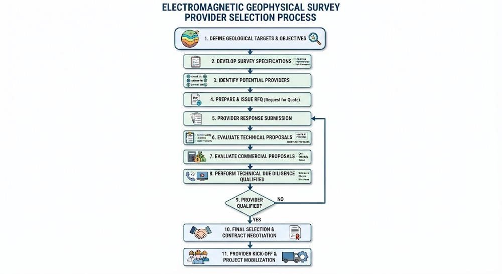
A practical selection process can be summarized as:
- Define the geological target
- Identify the expected physical contrast
- Determine whether EM is the appropriate method
- Select FDEM, TDEM/TEM, VLF, CSAMT, MT or airborne EM
- Shortlist providers with relevant project experience
- Review and score technical proposals
- Compare survey geometry and QA/QC plans
- Compare processing and interpretation scope
- Compare deliverables and commercial terms
- Select the provider based on total project fit
The most important procurement principle is simple: Do not buy an EM survey by the instrument name alone. Buy a technically defensible workflow.
Conclusion
Choosing an electromagnetic geophysical survey provider requires a broader assessment than equipment, company size or daily price. A capable provider should understand the geological objective, identify the relevant physical contrast, select an appropriate EM method, design a defensible survey, operate the equipment correctly, control data quality, process and invert the measurements, and explain the results within their geological limitations.
The strongest proposal is therefore not necessarily the one with the most expensive equipment or the lowest quotation. It is the proposal that provides the clearest connection between: Geological Objective → Physical Contrast → EM Method → Survey Design → Data Quality → Processing → Interpretation → Decision
This framework gives mining companies, environmental consultants, engineering firms, groundwater specialists, infrastructure owners and research institutions a practical, repeatable approach for selecting an electromagnetic geophysical survey provider.
Reference Sources
| Related Websites | URL |
|---|---|
| US EPA — Electromagnetic Methods | https://archive.epa.gov/esd/archive-geophysics/web/html/electromagnetic_methods.html |
| USGS — Airborne Electromagnetic Surveys | https://www.usgs.gov/mission-areas/water-resources |
| Society of Exploration Geophysicists (SEG) | https://seg.org/ |
| ASTM D6429 Standard Guide | https://www.astm.org/d6429-20.html |
| Geotech EM Survey Guide | https://geotechcn.net/service/electromagnetic-geophysical-survey-guide/ |
Related Articles
| Article Title | URL |
|---|---|
| Electromagnetic Geophysical Survey: EM Methods Guide 2026 | https://geotechcn.net/service/electromagnetic-geophysical-survey-guide/ |
| ERT vs TEM: Which Geophysical Method Fits Your Project? | https://geotechcn.net/service/ert-vs-tem-guide/ |
| What Are Resistivity Meters? Complete Technical Guide | https://geotechcn.net/service/what-are-resistivity-meters/ |
| What is Induced Polarization (IP) Method? | https://geotechcn.net/service/what-is-induced-polarization-ip-method-a-comprehensive-technical-guide/ |
| Geophysical Surveying: Ultimate Technology Guide | https://geotechcn.net/service/geophysical-surveying-explained/ |
FAQ
Q1: How do I choose the right electromagnetic geophysical survey provider?
Direct answer: Start by defining your geological target and expected physical contrast, then evaluate providers on method expertise, relevant project experience, QA/QC protocols and inversion capabilities, not just daily rates. Technical explanation: A qualified provider must connect EM method selection to target properties, design appropriate survey geometry, and deliver traceable quality control throughout fieldwork, processing and interpretation. Practical application: This structured approach reduces project risk for mineral exploration, environmental monitoring and civil engineering surveys.
Q2: What is the difference between frequency-domain and time-domain EM surveys?
Direct answer: Frequency-domain EM uses continuous excitation for rapid near-surface conductivity mapping, while time-domain TEM uses pulsed fields for deeper subsurface exploration. Technical explanation: FDEM delivers fast areal coverage at shallow depths; TEM records transient decay responses to image conductive targets at tens to hundreds of meters depth, depending on loop size and power. Practical application: Choose FDEM for topsoil salinity and shallow utility detection; use TEM for deep mineral exploration and groundwater aquifer mapping.
Q3: How deep can electromagnetic geophysical surveys reliably detect targets?
Direct answer: Reliable detection depth varies by method: 0.5–60m for frequency-domain EM, 20–800m+ for time-domain TEM, depending on geological conditions and target conductivity. Technical explanation: Maximum theoretical depth is not equal to reliable target detection; actual performance depends on target size, conductivity contrast, noise levels and survey geometry. Practical application: Deep TEM surveys are commonly used for base metal exploration and deep groundwater mapping; shallow FDEM serves agricultural and environmental site assessments.
Q4: Why is QA/QC important when selecting an EM survey provider?
Direct answer: Formal QA/QC ensures data accuracy, repeatability and interpretability by standardizing instrument calibration, field checks, processing controls and interpretation validation. Technical explanation: Without structured QA, data may contain position errors, noise artifacts and processing biases that lead to incorrect geological interpretation and project risk. Practical application: QA/QC is particularly critical for regulatory reporting, dam safety monitoring and mineral exploration programs that rely on survey data for drilling decisions.
Q5: Should I receive raw EM survey data from my provider?
Direct answer: Yes, you should request both raw and processed EM data deliverables, not just a final interpretation report. Technical explanation: Raw data enables independent reanalysis, future reinterpretation and integration with other geophysical datasets, reducing long-term dependency on a single contractor. Practical application: Standard deliverable packages should include raw field data, processed conductivity models, inversion files, GIS layers and a full technical report with limitations.