Welcome to Geotech!
-1.png)


Proton Precession Measurement: How Proton Precession Works in Magnetic Field Detection
Overview:Proton precession measurement is a magnetic field measurement technique based on the relationship between proton precession frequency and magnetic field strength. A Proton Precession Magnetometer polarizes hydrogen-rich fluid, detects the free-precession signal after the polarizing field is removed, and calculates the magnetic field from the measured Larmor frequency. This guide explains the physical principle, measurement sequence, signal interpretation, and practical factors that affect measurement reliability.

I. What Is Proton Precession Measurement?
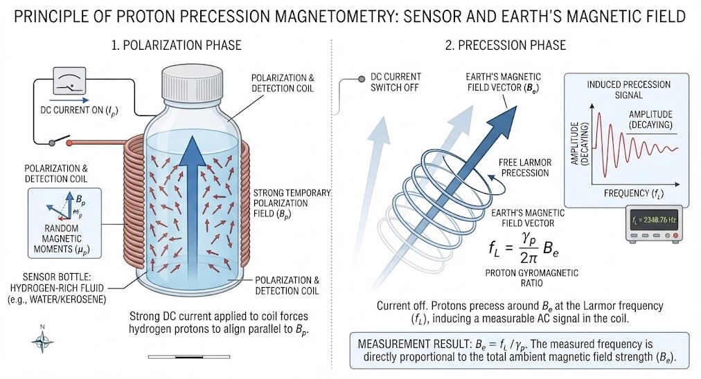
Proton precession measurement is a magnetic field measurement method that determines magnetic field strength by detecting the precession frequency of hydrogen nuclei (protons) in a magnetic field.
The technique is commonly implemented in a Proton Precession Magnetometer (PPM), also known as a proton magnetometer or nuclear magnetic resonance magnetometer.
Unlike instruments that directly measure magnetic field components through a sensor’s directional response, a conventional proton precession magnetometer derives the magnitude of the magnetic field from the frequency of a nuclear precession signal.
1. The Basic Measurement Concept
The measurement relies on three physical processes:
- Polarization: A strong temporary magnetic field creates a preferred alignment of proton magnetic moments in a hydrogen-rich liquid.
- Free precession: When the polarizing field is removed, the proton magnetization evolves in the ambient magnetic field and produces a precession signal.
- Frequency measurement: The instrument detects the signal frequency and converts it into magnetic field strength using the proton gyromagnetic ratio.
The result is a measurement of the magnetic field magnitude at the sensor location, rather than a direct measurement of individual vector components.
2. What Does a Proton Magnetometer Measure?
A conventional proton precession magnetometer measures the total magnetic field magnitude, commonly expressed in nanoteslas (nT).
The Earth’s magnetic field can be represented by three orthogonal components:
[
F=\sqrt{X^2+Y^2+Z^2}
]
Where:
- (F) is the total magnetic field magnitude.
- (X), (Y), and (Z) are the orthogonal field components.
A proton precession magnetometer measures (F), not each component independently. This distinction matters when selecting an instrument for geomagnetic monitoring, directional magnetic measurements, or magnetic anomaly surveys.
II. The Physics Behind Proton Precession
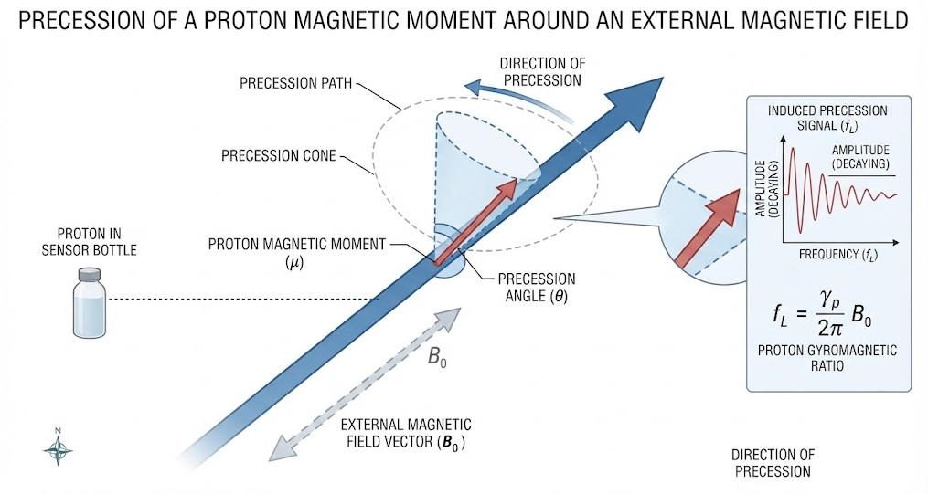
The physical foundation of proton precession measurement is the interaction between the magnetic moment of a proton and an external magnetic field.
1. Proton Magnetic Moment
A proton has an intrinsic quantum property called spin, associated with a magnetic moment. When protons are placed in a magnetic field, their magnetic moments interact with that field.
In a hydrogen-rich liquid, a large number of protons contribute to the net magnetization. Under suitable conditions, this collective magnetization can produce a measurable signal after the polarizing field is removed.
The instrument does not track individual protons. It detects the weak electrical signal associated with the collective behavior of the proton ensemble.
2. Larmor Precession
In a static magnetic field, the proton magnetic moment undergoes precession around the field direction. This motion is known as Larmor precession.
The precession frequency is proportional to the magnetic field magnitude:
[
f=\frac{\gamma_p}{2\pi}B
]
Where:
- (f) = proton precession frequency in hertz (Hz).
- (\gamma_p) = proton gyromagnetic ratio in radians per second per tesla.
- (B) = magnetic field magnitude in teslas (T).
For protons, the gyromagnetic ratio expressed in frequency units is approximately:
[
\frac{\gamma_p}{2\pi}\approx42.577\ \text{MHz/T}
]
Therefore, a stronger magnetic field produces a higher precession frequency.
3. Why Frequency Can Be Used to Measure Magnetic Field
The proton gyromagnetic ratio is a well-established physical constant. Once the precession frequency is measured, the magnetic field can be calculated:
[
B=\frac{2\pi f}{\gamma_p}
]
This relationship makes proton precession measurement a frequency-based magnetic field measurement technique.
For a typical terrestrial magnetic field of approximately 50,000 nT, the proton precession frequency is about 2,129 Hz.
The frequency-to-field relationship is highly useful because frequency can be measured electronically with precision. However, the final measurement accuracy still depends on signal quality, instrument design, timing, environmental conditions, and calibration.
III. How Proton Precession Measurement Works: Step by Step
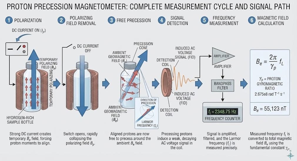
A proton precession magnetometer performs a sequence of operations to convert proton behavior into a numerical magnetic field reading.
1. Step One: Proton Polarization
The sensor contains a hydrogen-rich liquid, such as a suitable water-based or hydrocarbon-based fluid, depending on the instrument design.
A current is passed through a coil surrounding the fluid. The coil generates a temporary polarizing magnetic field, which produces a net alignment of proton magnetic moments.
This process is called proton polarization.
The polarizing field is generally stronger than the ambient magnetic field so that the sensor can establish a measurable net magnetization.
2. Step Two: Removal of the Polarizing Field
The polarizing current is switched off. The strong temporary field collapses, leaving the proton ensemble exposed primarily to the ambient magnetic field.
The transition between polarization and free precession is a critical part of the measurement cycle.
Switching behavior, residual fields, and the time required for the signal to become detectable can influence measurement quality.
3. Step Three: Free Precession
After the polarizing field is removed, the net proton magnetization evolves around the direction of the ambient magnetic field.
This motion is called free precession.
The precession frequency is governed by the magnetic field magnitude and the proton gyromagnetic ratio. In a stable field, the frequency remains approximately constant during the observable signal interval.
The precessing magnetization produces a changing magnetic flux through the sensor coil.
4. Step Four: Induced Signal Detection
The changing magnetic flux induces a weak electrical signal in the sensor coil.
The signal is typically a damped oscillation rather than a sustained waveform. Its amplitude decreases over time because of relaxation and dephasing processes.
The instrument amplifies and conditions the signal so that the precession frequency can be extracted.
The quality of the detected signal depends on the sensor design, signal amplitude, environmental electromagnetic noise, and the timing of the acquisition process.
5. Step Five: Frequency Estimation
The instrument estimates the frequency of the detected oscillation.
Depending on the instrument architecture, frequency estimation may use zero-crossing detection, digital counting, waveform fitting, or other signal-processing techniques.
The objective is to determine the precession frequency accurately from a finite-duration signal.
6. Step Six: Magnetic Field Calculation
The measured frequency is converted into magnetic field magnitude using the proton gyromagnetic ratio:
[
B=\frac{f}{\gamma_p/(2\pi)}
]
The result is commonly displayed in nanoteslas (nT).
The instrument may also store the measurement time, location, sensor status, and other survey information for subsequent interpretation.
Table 1. Proton Precession Measurement Workflow
| Measurement Stage | Physical or Technical Process | Result |
|---|---|---|
| Polarization | Temporary magnetic field aligns proton magnetic moments | Net magnetization |
| Field removal | Polarizing current is switched off | Transition to free precession |
| Free precession | Proton magnetization evolves in the ambient field | Frequency-dependent magnetic signal |
| Signal detection | Coil detects induced voltage | Electrical waveform |
| Frequency estimation | Electronics determine oscillation frequency | Precession frequency |
| Field calculation | Frequency is converted using the gyromagnetic ratio | Magnetic field magnitude |
IV. The Relationship Between Larmor Frequency and Magnetic Field Strength
The Larmor frequency is the central measurable quantity in proton precession measurement.
1. Frequency-to-Field Conversion
The proton precession frequency changes linearly with magnetic field strength.
For practical calculations, the approximate relationship is:
[
f\ (\text{Hz})\approx42.577\times B\ (\mu\text{T})
]
For example, if the magnetic field magnitude is 50 μT:
[
f\approx42.577\times50=2128.85\ \text{Hz}
]
This corresponds to a precession frequency of approximately 2.13 kHz.
2. Example of Magnetic Field Calculation
Suppose a proton precession magnetometer detects a precession frequency of 2,130 Hz.
Using the approximate proton gyromagnetic ratio:
[
B=\frac{2130}{42.577}\approx50.03\ \mu\text{T}
]
Converting to nanoteslas:
[
50.03\ \mu\text{T}\approx50,030\ \text{nT}
]
This example illustrates the conversion principle. Actual instrument calculations use the applicable physical constants, measurement conventions, and calibration parameters.
Table 2. Illustrative Frequency and Magnetic Field Relationship
| Magnetic Field Magnitude | Approximate Proton Precession Frequency |
|---|---|
| 25 μT | 1,064.4 Hz |
| 40 μT | 1,703.1 Hz |
| 50 μT | 2,128.9 Hz |
| 60 μT | 2,554.6 Hz |
| 65 μT | 2,767.5 Hz |
These are theoretical examples based on the proton gyromagnetic ratio, not product specifications.
V. Signal Processing in Proton Precession Measurement
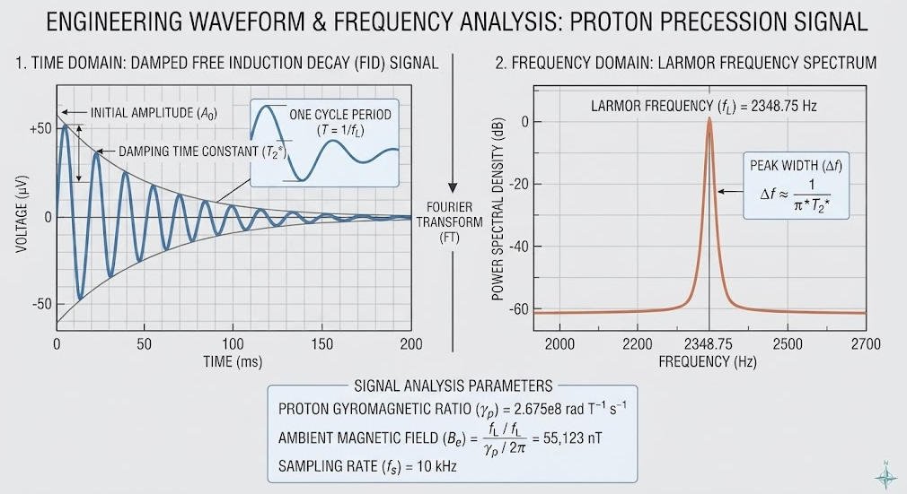
The detected precession signal is often weak and decays with time. Signal processing is therefore essential for obtaining a reliable frequency estimate.
1. Signal Amplification and Conditioning
The sensor coil produces a small electrical signal. The front-end electronics amplify and condition this signal for subsequent analysis.
Signal conditioning may include filtering, gain control, and suppression of unwanted electrical interference.
Poor signal conditioning can reduce the usable measurement interval or increase uncertainty in the estimated frequency.
2. Frequency Estimation Methods
Several methods can be used to estimate the precession frequency.
| Method | Principle | Practical Consideration |
|---|---|---|
| Zero-crossing detection | Measures timing between waveform crossings | Sensitive to noise and waveform distortion |
| Digital frequency counting | Counts cycles or measures timing intervals | Depends on timing reference and signal quality |
| Waveform fitting | Fits a mathematical model to sampled data | Can improve estimation when the signal model is appropriate |
| Spectral analysis | Identifies the dominant frequency component | Frequency resolution depends on signal duration and processing |
Not every proton precession magnetometer uses all these methods. The actual signal-processing architecture depends on the instrument design.
3. Signal Decay and Measurement Duration
The precession signal gradually loses amplitude as the proton ensemble dephases and relaxes.
A longer usable signal can provide more information for frequency estimation, but only if the signal remains sufficiently stable and distinguishable from noise.
The instrument must balance acquisition duration, signal amplitude, interference, and the required measurement rate.
VI. Factors Affecting Proton Precession Measurement Accuracy
The physical relationship between frequency and magnetic field is well defined. Practical measurement uncertainty arises from the complete measurement chain.
1. Signal-to-Noise Ratio
A weak signal can be obscured by electrical noise, nearby equipment, power lines, or other magnetic disturbances.
A higher signal-to-noise ratio generally makes frequency estimation more reliable.
2. Timing Reference Stability
Frequency measurement depends on the stability and accuracy of the instrument’s timing reference.
Timing errors can translate into frequency errors and, consequently, magnetic field errors.
3. Sensor Position and Orientation
A proton precession magnetometer measures the total field magnitude, but sensor location still matters.
Nearby magnetic materials, ferrous objects, vehicles, fences, and electrical equipment can alter the local field.
Sensor orientation can also influence signal strength and the quality of the detected waveform, depending on sensor design and the angle between the sensor axis and the ambient field.
4. Environmental Magnetic Variations
The Earth’s magnetic field changes with time and location.
Daily geomagnetic variations, magnetic storms, nearby moving metal objects, and local infrastructure can affect the measured field.
For surveys requiring small-anomaly detection, these variations must be considered during acquisition and interpretation.
5. Instrument Condition and Calibration
Sensor condition, electronic stability, temperature, and instrument-specific calibration parameters may affect the measurement.
Calibration should follow the manufacturer’s procedures and the requirements of the survey.
Table 3. Measurement Error Sources and Quality-Control Measures
| Potential Error Source | Possible Effect | Recommended Control |
|---|---|---|
| Electromagnetic noise | Distorted or unstable signal | Select a suitable measurement location and reduce nearby interference |
| Timing-reference error | Frequency bias | Use a stable, verified timing system |
| Nearby magnetic objects | Local field distortion | Maintain consistent clearance from magnetic materials |
| Poor sensor positioning | Inconsistent readings | Standardize sensor height and placement |
| Weak signal | Unstable frequency estimation | Check sensor condition and signal quality |
| Instrument drift or malfunction | Systematic measurement error | Follow calibration and maintenance procedures |
| Temporal geomagnetic variation | Changes unrelated to the target anomaly | Use appropriate base-station correction or repeat measurements |
VII. Proton Precession Magnetometer vs. Other Magnetic Measurement Technologies
Proton precession measurement is one of several approaches to magnetic field measurement. Different technologies serve different measurement objectives.
1. Proton Precession Magnetometer vs. Fluxgate Magnetometer
A proton precession magnetometer typically measures the total magnetic field magnitude. A fluxgate magnetometer measures magnetic field components along its sensor axes.
The choice depends on whether the survey requires total-field measurements, vector components, continuous monitoring, or a particular sampling rate.
Table 4. Comparison of Magnetic Measurement Technologies
| Technology | Measurement Output | Typical Strength | Key Consideration |
|---|---|---|---|
| Proton precession magnetometer | Total magnetic field magnitude | Frequency-based measurement with a well-defined physical relationship | Measurement cycle and signal acquisition time |
| Overhauser magnetometer | Total magnetic field magnitude | Often supports faster measurement cycles than conventional PPM designs | Requires suitable instrument design and operating conditions |
| Fluxgate magnetometer | Magnetic field vector components | Continuous vector measurement | Sensor orientation, offset, and calibration |
| Optically pumped magnetometer | Magnetic field magnitude or components, depending on design | High sensitivity and fast response in suitable configurations | Technology-specific operating conditions and instrument complexity |
No single technology is suitable for every survey. Instrument selection should consider the required field quantity, sensitivity, sampling rate, environmental conditions, and project budget.
VIII. Applications of Proton Precession Measurement

Proton precession measurement is used in applications that require total magnetic field measurements.
1. Mineral Exploration
In mineral exploration, magnetic surveys identify variations in the Earth’s magnetic field associated with magnetic minerals and geological structures.
A proton precession magnetometer can collect total-field measurements along survey lines. The resulting data can help identify magnetic anomalies for further geological investigation.
A magnetic anomaly is not proof of an economic mineral deposit. Geological mapping, geochemical sampling, drilling, or other methods may be needed to evaluate a target.
2. Archaeological and Engineering Surveys
Magnetic surveys can help identify buried features that produce detectable magnetic contrasts.
Applications may include archaeological investigations, mapping of buried ferrous objects, and selected engineering or environmental surveys.
The suitability of a proton precession magnetometer depends on the expected anomaly size, measurement spacing, local magnetic noise, and survey requirements.
3. Geomagnetic Monitoring
Proton precession magnetometers can be used to measure total-field changes over time.
When paired with suitable recording and reference systems, they can contribute to geomagnetic observation and magnetic variation monitoring.
For continuous vector monitoring, a fluxgate or another suitable sensor may be required.
4. Magnetic Gradient Surveys
A magnetic gradient can be estimated by comparing measurements from two locations or sensors.
For two total-field measurements:
[
G\approx\frac{B_2-B_1}{\Delta r}
]
Where:
- (G) is the estimated gradient along the measurement direction.
- (B_1) and (B_2) are magnetic field measurements.
- (\Delta r) is the distance between measurement locations.
Gradient measurements can help emphasize local magnetic variations, but their reliability depends on sensor geometry, synchronization, positioning, and environmental conditions.
IX. How to Select a Proton Precession Magnetometer
Choosing a proton precession magnetometer requires matching instrument performance to the survey’s technical requirements.
1. Define the Measurement Objective
Before comparing instruments, determine whether the project requires:
- Total magnetic field mapping.
- Magnetic anomaly detection.
- Base-station monitoring.
- Gradient measurement.
- Archaeological or engineering magnetic surveys.
The measurement objective determines the required sensor configuration and data acquisition strategy.
2. Evaluate Technical Parameters
| Parameter | Why It Matters |
|---|---|
| Measurement range | Must cover the expected ambient magnetic field |
| Sensitivity and noise | Affect the ability to resolve small field variations |
| Resolution | Determines the smallest displayed or recorded increment |
| Absolute accuracy | Indicates how closely a reading represents the true field under specified conditions |
| Measurement cycle | Affects survey speed and spatial sampling |
| Environmental rating | Determines suitability for field conditions |
| Data storage and export | Supports survey documentation and processing |
| Sensor configuration | Determines whether single-point or gradient measurements are practical |
Sensitivity, resolution, and accuracy are distinct specifications and should not be treated as interchangeable.
3. Consider the Complete Survey System
The magnetometer is only one part of a magnetic survey system.
A complete solution may also require positioning equipment, a base station, field data management software, survey planning, and interpretation tools.
The best configuration depends on the project scale, expected anomaly characteristics, terrain, and required data quality.
X. Geotech Proton Magnetometer Solutions
Geotech provides magnetic exploration instruments for geophysical fieldwork. Its JPMG series is designed for total-field magnetic measurement and related survey applications.
Potential configuration choices include single-sensor and dual-sensor systems, depending on the survey objective.
1. Single-Sensor Configuration
A single-sensor proton magnetometer is suitable for measuring total magnetic field intensity at individual survey points.
Typical use cases include:
- Total-field magnetic mapping.
- Geological magnetic surveys.
- Reference measurements and selected monitoring tasks.
2. Dual-Sensor Configuration
A dual-sensor configuration can support simultaneous measurements at two sensor positions.
When the system is designed and configured for gradient work, the difference between the two readings can be used to estimate a magnetic field gradient.
Actual gradient performance depends on sensor spacing, synchronization, instrument specifications, and field conditions.
3. Product Selection
Explore Geotech’s magnetic instrument range:
- Magnetic Instruments: https://geotechcn.net/products/magnetic-instrument/
- Single-Sensor Proton Magnetometer: https://geotechcn.net/products/magnetic-instrument/proton-magnetometer-single/
- Dual-Sensor Proton Magnetometer: https://geotechcn.net/products/magnetic-instrument/dual-sensor-proton-magnetometer/
For product selection, confirm the current specifications, measurement cycle, environmental ratings, and sensor configuration with the manufacturer.
XI. Conclusion
Proton precession measurement converts the behavior of hydrogen nuclei into a practical magnetic field measurement through a well-defined frequency-to-field relationship.
The process involves proton polarization, free precession, induced signal detection, frequency estimation, and magnetic field calculation.
Understanding these stages helps engineers evaluate measurement quality, select appropriate equipment, and interpret magnetic survey data more reliably.
For geophysical applications, the value of a proton precession magnetometer depends not only on its physical principle but also on the instrument design, field conditions, survey configuration, and data quality-control procedures.
Related Articles
| Anchor Text | Target URL | Core Content |
|---|---|---|
| Proton Precession Magnetometer | https://geotechcn.net/service/proton-precession-magnetometer-3/ | Instrument structure, measurement workflow, and field applications |
| Proton Magnetometer Working Principle | https://geotechcn.net/service/proton-magnetometer-from-hydrogen-atom-polarization-to-accurate-magnetic-field-measurement/ | Proton polarization and physical measurement principle |
| Proton Precession Magnetometer Technical Analysis | https://geotechcn.net/service/proton-precession-magnetometer-2/ | Polarization, magnetic moment, and measurement accuracy |
| Single-Sensor Proton Magnetometer | https://geotechcn.net/products/magnetic-instrument/proton-magnetometer-single/ | Single-sensor product configuration |
| Dual-Sensor Proton Magnetometer | https://geotechcn.net/products/magnetic-instrument/dual-sensor-proton-magnetometer/ | Dual-sensor configuration and gradient measurement |
| Magnetic Instruments | https://geotechcn.net/products/magnetic-instrument/ | Magnetic exploration instrument portfolio |
Reference Sources
| Organization / Source | Reference URL | Core Content |
|---|---|---|
| U.S. Geological Survey (USGS) | https://pubs.usgs.gov/of/1981/1346/report.pdf | Proton precession magnetometer principle and field measurement |
| U.S. Geological Survey (USGS) | https://www.usgs.gov/ | Geomagnetic science and magnetic field measurement resources |
| Society of Exploration Geophysicists (SEG) | https://seg.org/ | Geophysical exploration methods and professional resources |
| American Physical Society (APS) | https://journals.aps.org/pr/ | Foundational nuclear magnetic resonance research |
| International Union of Geodesy and Geophysics (IUGG) | https://www.iugg.org/ | Geomagnetic and geophysical research resources |
FAQ
Q1. What is proton precession measurement?
Proton precession measurement is a magnetic field measurement technique that determines field magnitude from the precession frequency of hydrogen nuclei. A proton precession magnetometer polarizes a hydrogen-rich medium, detects the free-precession signal, and converts its frequency into a magnetic field value using the proton gyromagnetic ratio.
Q2. How does a proton precession magnetometer measure magnetic fields?
The instrument applies a temporary polarizing magnetic field to a hydrogen-rich liquid. After the field is removed, the proton magnetization precesses in the ambient field and induces a weak electrical signal in a coil. The instrument measures the signal frequency and calculates the magnetic field magnitude.
Q3. What is the Larmor frequency in proton precession measurement?
The Larmor frequency is the rate at which proton magnetic moments precess around an external magnetic field. It is directly proportional to the field magnitude. For protons, the frequency is approximately 42.577 MHz per tesla, making it possible to calculate the magnetic field from the measured frequency.
Q4. Does a proton precession magnetometer measure magnetic field direction?
A conventional proton precession magnetometer measures the total magnetic field magnitude rather than independent vector components. It does not directly provide the field direction. A fluxgate magnetometer or another vector-capable instrument is more suitable when directional magnetic field information is required.
Q5. What affects the accuracy of proton precession measurement?
Accuracy can be affected by signal-to-noise ratio, timing-reference stability, sensor design, nearby magnetic objects, environmental magnetic variations, and instrument condition. Reliable measurements require suitable field procedures, consistent sensor positioning, appropriate calibration, and quality control matched to the survey objective.