Welcome to Geotech!
-1.png)


What is ATEM Systems?How does it work?
TIPS:Airborne Transient Electromagnetic (ATEM) methods are reshaping exploration in complex terrains. This guide breaks down Airborne Transient Electromagnetic principles, compares helicopter TEM systems like VTEM and SkyTEM, and explains data processing workflows. Whether you are sourcing airborne electromagnetic equipment or optimizing helicopter TEM system operations, this article provides actionable technical insights.
ATEM Systems: Principles & Applications
Airborne Transient Electromagnetic (ATEM) method uses a flight platform for electromagnetic detection. It needs no ground crew in the survey area. Steep mountains, deserts, lakes, swamps, and forests are all accessible. ATEM transmits pulsed electromagnetic fields and receives subsurface responses. It extracts geo-electrical information. The method serves mineral, oil, gas, and groundwater exploration worldwide.
I. Airborne TEM Technology: A Survey Tool for Complex Terrain
Traditional ground EM methods face severe terrain limits. Steep mountains, dense forests, and swamps often block access. Ground crews struggle to reach survey points. Operations are slow, costly, and risky.
ATEM technology changes this completely. Flight platforms carry transmitters and receivers. Helicopters or fixed-wing aircraft fly over the survey block. EM signals penetrate the surface and probe subsurface electrical structures. A single flight covers tens to hundreds of square kilometers. Survey efficiency rises by orders of magnitude compared to ground methods.
ATEM offers three core strengths. First, strong terrain adaptability. Flight platforms ignore ground conditions. Second, high survey speed. Large-area reconnaissance cycles shrink dramatically. Third, high data quality. Modern systems balance shallow resolution with deep penetration.
Today, ATEM is a mainstream technology for global mineral exploration and groundwater investigation. Major mining companies and geological surveys routinely use helicopter TEM systems for early-stage reconnaissance.
II. ATEM Principles: The Space-Time Link of Electromagnetic Induction
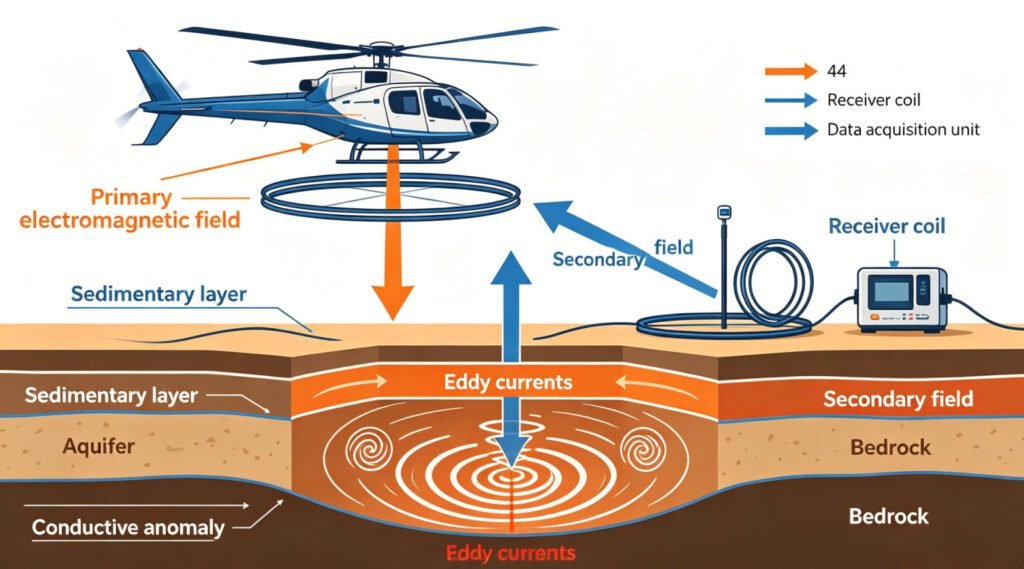
ATEM rests on the law of electromagnetic induction. The system transmits pulsed EM fields through a transmitter loop. This field is the primary field. It induces eddy currents in conductive subsurface media. These currents decay under Ohmic effects. The decay process generates a new EM field. This is the secondary field. Receivers measure the secondary field. Analysts extract geo-electrical information from its space-time characteristics.
1. Primary Field Excitation and Eddy Current Generation
The transmitter loop carries pulsed current. The current creates a strong magnetic field. This field penetrates the surface and enters subsurface media. Conductive rock layers and ore bodies generate induced eddy currents. The distribution of these currents depends on subsurface electrical structure. High-conductivity bodies produce strong currents. Low-resistance formations show clear responses.
2. Secondary Field Decay and Geo-Electrical Extraction
After the primary field shuts off, eddy currents begin to decay. Decay speed is controlled by subsurface resistivity. Highly conductive areas decay slowly. High-resistivity zones decay fast. Early secondary field response reflects shallow information. Late response reflects deep structure. The receiver samples data in multiple time windows. Multi-channel data builds subsurface electrical profiles.
III. Three Technical Bottlenecks and Engineering Breakthroughs
ATEM systems are not simple aerial adaptations of ground equipment. Flight platforms impose strict limits on power supply and payload weight. Aerodynamic requirements further constrain design space. Systems must achieve large dipole moment, fast turn-off, and low noise under multiple constraints.
1. Transmitter Side: The Trade-Off Between Large Moment and Fast Turn-Off
Dipole moment determines exploration depth. The formula is M = N × I × A. N is turns, I is current, A is loop area. Increasing moment requires higher current or larger loop. But aerial platforms have limited payload. Larger loops increase frame weight. Aerodynamic drag rises. Flight safety drops.
Fast turn-off determines shallow resolution. Turn-off time toff is proportional to loop self-inductance L. Large loops have high inductance. Turn-off time is hard to shorten. Long turn-off loses high-frequency information. Shallow thin-layer resolution suffers.
Engineering solutions include optimized waveform design. Bipolar trapezoidal waves control the falling-edge slope. This balances moment and bandwidth. Advanced systems like VTEM Supermax achieve 1.3 MAm² peak moment. Turn-off time is controlled to hundreds of microseconds.
2. Receiver Side: Near-Source Saturation and Noise Suppression
Transmitter and receiver loops are close together. The primary field during transmission is extremely strong. Receiver systems easily saturate. Saturation masks the secondary field signal in the off-time window. Full waveform processing becomes impossible.
Engineers use three strategies. Strategy one: increase transmitter-receiver separation. Place the sensor about 30 meters above the transmitter loop. The primary field decays into the dynamic range. But sensor height above ground increases. Useful signal weakens further.
Strategy two: bucking coil compensation. The compensation coil shares the center with the transmitter loop. It produces reverse magnetic flux at the sensor position. This cancels the primary field. But assembly precision limits compensation. Residual primary field still affects data quality.
Strategy three: zero-position placement. The induction coil straddles the transmitter loop. Positive and negative primary flux cancel each other. But ground calibration mixes secondary field into data. After takeoff, secondary field amplitude changes. Zero-position deviation introduces systematic errors.
Modern systems use digital signal processing to compensate for hardware limits. Dual-gain channel strategies expand dynamic range. Multi-channel synchronous acquisition improves data reliability.
3. Aerial Adaptation: Aerodynamics and Payload Limits
Transmitter frames must withstand high-speed airflow. Rigid-frame systems offer high structural integrity. But they are heavy and complex to modify. Soft-frame systems are lightweight. They have good aerodynamic characteristics. But flight attitude stability is poor. Attitude changes introduce motion noise.
Excellent aerodynamic design balances structural strength, weight, and stability. Carbon fiber composite frames are now widely used. They ensure strength while controlling weight.
IV. Global HTEM System Comparison and Selection Guide
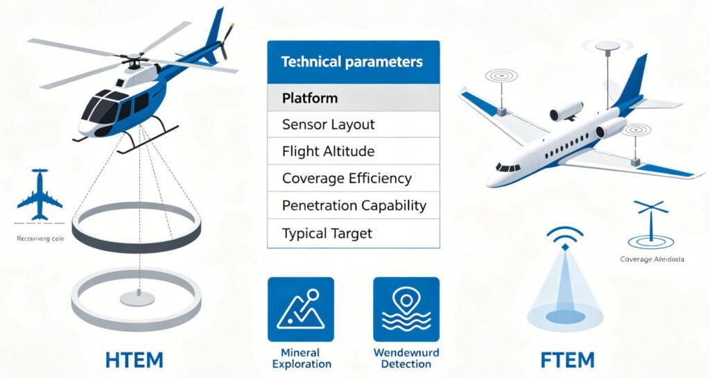
By platform, ATEM divides into fixed-wing (FTEM) and helicopter (HTEM) types. After the 1970s, fixed-wing dominated due to payload advantages. But since the 21st century, HTEM technology has advanced rapidly. Helicopters offer excellent low-altitude, low-speed performance. They enable finer detection. Temporary landing sites are flexible. Maintenance costs are lower. HTEM has gradually become the international mainstream.
1. VTEM Series: Industry Benchmark for High Signal-to-Noise Ratio
Canadian company Geotech developed the VTEM system in 2002. The system follows a continuous complex upgrade strategy. Core optimization directions include noise reduction, moment increase, waveform optimization, decay measurement window extension, and acquisition precision improvement.
VTEM has demonstrated superior performance in multiple international comparisons. The Greenland project showed VTEM investigation depth exceeds SkyTEM by 4 to 5 times. Weak and shallow conductor identification is significantly better than competitors. Late-time noise is 20 to 25 times lower. Early-time noise is 18 to 20 times lower. Over the same survey block, VTEM identified 25 to 28 reliable targets. SkyTEM identified only 7 to 8.
VTEM Supermax achieves about 1.3 MAm² peak moment. This exceeds most fixed-wing systems. The system suits deep mineral exploration. It offers high sensitivity to conductive ore bodies.
2. SkyTEM Series: Wide-Band Advantage with Multi-Frequency Excitation
Danish company SkyTEM Aps collaborated with Aarhus University. They launched the first system in 2004. The core innovation is multi-base-frequency excitation. The system configures two independent transmitters. One transmits short signals at 222 Hz base frequency. The other transmits long signals at 25 Hz base frequency. This achieves wide-band continuous excitation.
SkyTEM301 focuses on near-surface mapping. SkyTEM304/312 are medium-duty systems. SkyTEM508 and 516 target deep investigation. The 516 peak moment exceeds 1 MAm². It successfully detected the deeply buried Caber North deposit.
SkyTEM’s strength lies in the shortest transmitter turn-off and earliest decay sampling. Near-surface characterization precision is high. Groundwater exploration applications are extensive.
3. HeliTEM and Fixed-Wing Systems: Scenario-Specific Choices
French company CGG offers HeliTEM and fixed-wing MEGATEM systems. MEGATEM peak moment is about 1 MAm². Fixed-wing suits large-area rapid reconnaissance. But airport dependency is high. Non-productive flight time is long. Economics are weaker.
Selection advice: Choose HTEM for deep, detailed exploration. Choose FTEM for large-area rapid screening. SkyTEM has advantages for near-surface hydrogeological surveys. VTEM is more reliable for deep, highly conductive ore bodies.

V. Chinese Indigenous AEM Equipment: From Import to Innovation
Chinese ATEM research began in the early reform era. Institutes including the former Ministry of Geology’s geophysical and geochemical exploration institute, the airborne geophysics and remote sensing center, Changchun College of Geology, and Beijing Geological Instrument Factory all conducted studies. Early work remained incomplete due to funding shortages. After 2000, the industry reached consensus: time-domain airborne EM methods hold the greatest potential.
1. CHTEM System: Rigid-Frame Domestic Breakthrough
After 2010, the Airborne Geophysics and Remote Sensing Center collaborated with Jilin University and other partners. They imported and digested AeroTEM-IV technology from Canadian company Aeroquest. They developed China’s first rigid-frame helicopter TEM system, CHTEM.
CHTEM uses central-loop configuration. Transmitter coil radius is 6 meters. 5 turns. Bipolar trapezoidal waveform. Falling edge is 1.2 milliseconds. Duty cycle is about 1:4.4. Maximum transmitter current is 450 A. Peak moment is about 0.26 MAm². Comparative tests proved performance fully exceeds AeroTEM-IV. It filled the domestic gap.
Upgraded versions boost current to 500 A. Falling edge is controlled within 1 millisecond. System stability is good. It suits complex domestic terrain operations.
2. CAS-HTEM System: Soft-Frame Large-Moment Practical Application
In 2013, the Institute of Electronics at the Chinese Academy of Sciences collaborated with Jilin University and Xiamen University. They imported the Russian Impulse-A5 system. After full technical mastery, they developed China’s first practical soft-frame large-moment helicopter EM detection system, CAS-HTEM.
Total system weight is 550 kg. Peak transmitter moment approaches 0.7 MAm². Peak current is 300 A. Turn-off time is 450 microseconds. Induction magnetic sensor noise reaches 0.1 nT/s.
The system adopts a dual-gain channel strategy. The same signal is amplified at different gains. Then it is synthesized into one channel. Gain settings include 1/4, 1, 2, 4, 8, and 16. Operators can set these according to field conditions.
Routine observation uses Z-axis magnetic field. The receiver has 6 channels. Every two channels form one group. Each group has one gain setting. The system supports three-axis observation.
Auxiliary sensors are comprehensive. They include aerial cameras, three-component attitude sensors, post-differential GPS, radar altimeters, and laser altimeters. These provide multi-source data for flight attitude error assessment and correction.
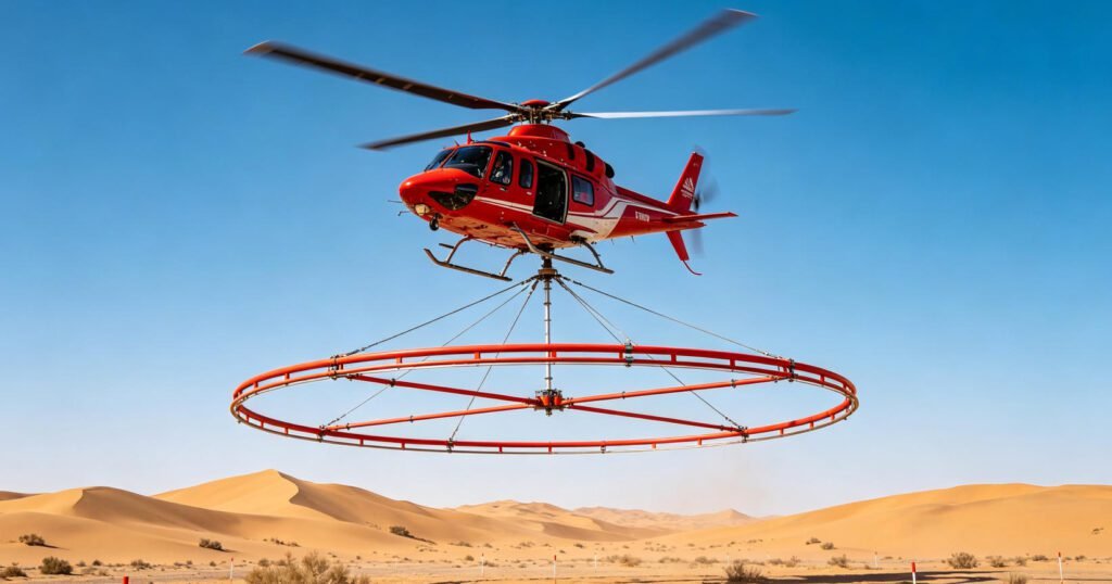
Chinese ATEM systems have gradually reached international advanced levels. Latecomer advantages include fully summarizing Western technical routes. This avoids early trial-and-error costs. Future directions point to UAV platforms and full waveform processing.
VI. Data Processing and Inversion Imaging: From Signal to Model
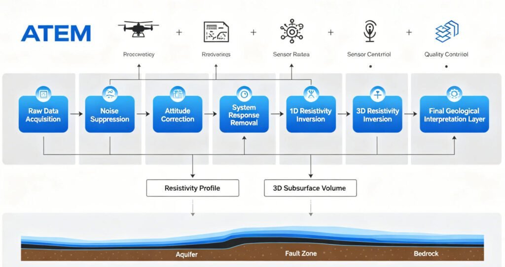
Hardware design solves data acquisition challenges. Data processing solves the various interferences introduced by aerial observation. Core tasks include three items: noise suppression, attitude correction, and system defect remediation.
1. Noise Suppression and Attitude Correction
Aerial observation introduces motion noise. Aircraft turbulence causes bird rotation, displacement, and tilt. Attitude effects alter the coupling between primary and secondary fields. Data quality degrades.
The processing flow includes: line data extraction, sferic noise processing, motion-induced noise removal, system response removal, stacking and windowing. Each step targets a specific noise source.
Motion noise removal uses adaptive filtering. Attitude correction fuses GPS, IMU, and altimeter data. System response removal corrects sensor frequency response through calibration curves. Full waveform processing further eliminates residual currents and transmitter drift.
2. Imaging and Inversion Methods
Imaging methods are fast and intuitive. Classic methods include lookup tables, CDI/CDT, and EMFlow. These methods compute quickly. They suit field quality control.
Inversion methods offer higher precision. One-dimensional inversion remains the mainstream. It assumes horizontal layered media. Inversion speed is fast. The technology is mature. It suits large-area reconnaissance.
High-dimensional inversion (2D/3D) provides finer geo-electrical parameter distribution. It handles complex structures and topography. But computation load is heavy. It remains a key research direction for domestic and international institutions. As computing power grows, 3D inversion will gradually become practical.
VII. Application Scenarios and Business Value: ROI Analysis
ATEM technology delivers business value through efficiency and cost advantages. Traditional ground EM methods take hours per station in complex areas. ATEM completes hundreds of stations per day. Unit area costs drop by 60% to 80%.
In mineral exploration, ATEM serves early-stage reconnaissance. It quickly delineates anomaly zones. It reduces blind drilling. It lowers exploration risk. Australia, Canada, and African mining nations apply it extensively.
For groundwater investigation, ATEM identifies aquifers. It distinguishes fresh and saline water. It guides well placement. Denmark and arid Australian regions have numerous successful applications.
In environmental engineering, ATEM detects contaminant plumes. It identifies landfill leakage. It assesses karst collapse risk. Non-intrusive surveys reduce environmental disturbance.
China’s “deep resource exploration” strategy drives ATEM demand growth. Indigenous systems cost less than imported equipment. Maintenance is convenient. Service response is fast. The cost-performance advantage is clear.
Reference Sources
| Authority | URL |
|---|---|
| Society of Exploration Geophysicists (SEG) | https://seg.org/ |
| European Association of Geoscientists and Engineers (EAGE) | https://www.eage.org/ |
| USGS Mineral Resources Program | https://www.usgs.gov/programs/mineral-resources-program |
| Geological Survey of Canada | https://www.nrcan.gc.ca/science-data/research-centres-labs/geological-survey-canada |
| International Association of Hydrogeologists (IAH) | https://iah.org/ |
FAQ
Q1: What is the difference between ATEM and Semi-Airborne TEM (SATEM)?
ATEM carries both transmitter and receiver on the flight platform. SATEM fixes the transmitter on the ground. The receiver coil flies and measures in the air. ATEM offers higher operational efficiency. But transmitter energy is limited by the platform. Investigation depth is constrained. SATEM offers greater transmitter power. It achieves deeper penetration. But ground transmitter deployment is complex. Operational efficiency is lower than ATEM.
Q2: How do I choose between helicopter TEM and fixed-wing systems?
Helicopter TEM systems offer excellent low-altitude, low-speed performance. They provide high resolution. Aircraft modification requirements are low. They can use temporary landing sites. They suit detailed exploration and small survey blocks. Fixed-wing systems have large payload capacity. They offer high power supply. They suit large-area rapid reconnaissance. But they depend on airports. Non-productive flight time is high. Maintenance costs are higher. Choose fixed-wing for deep reconnaissance. Choose helicopter for detailed surveys.
Q3: What are the main technical differences between VTEM and SkyTEM?
VTEM’s advantage lies in low noise and high signal-to-noise ratio. Late-time response is strong. Deep conductive target identification is superior. SkyTEM’s advantage lies in multi-frequency excitation. It has the shortest turn-off time. Near-surface resolution is highest. VTEM suits deep mineral exploration better. SkyTEM suits near-surface hydrogeological and environmental surveys better.
Q4: What is the biggest challenge in ATEM data processing?
Motion noise and attitude effects are the biggest challenges. Flight platform turbulence causes bird displacement and rotation. Data coupling relationships change. Correction requires fusing GPS, IMU, and altimeter data for attitude correction. The second challenge is near-source saturation from transmitter-receiver coupling. This requires precise bucking coil or zero-position design.
Q5: What level have Chinese indigenous airborne electromagnetic systems reached?
Chinese CHTEM and CAS-HTEM systems have reached international advanced levels. The CHTEM rigid-frame system exceeds the imported prototype AeroTEM-IV in performance. The CAS-HTEM soft-frame system achieves peak moment approaching 0.7 MAm². It supports three-axis observation and dual-gain channels. It has been successfully applied in deep resource exploration projects. Future evolution points to UAV platforms and full waveform processing.