Welcome to Geotech!
Proton Magnetometer Signal Modulation Due to Rotation (2026 Guide)
TIPS:This summary focuses on rotation-induced signal modulation of the proton magnetometer, a key issue for geomagnetic survey equipment. The proton magnetometer (also called proton precession magnetometer) needs stable signals, but rotation causes rotation-induced signal modulation—this affects data reliability in scenarios like drone magnetic gradient surveying. The proton magnetometer’s accuracy relies on addressing this modulation to avoid misidentifying subtle anomalies.
Ⅰ. Introduction
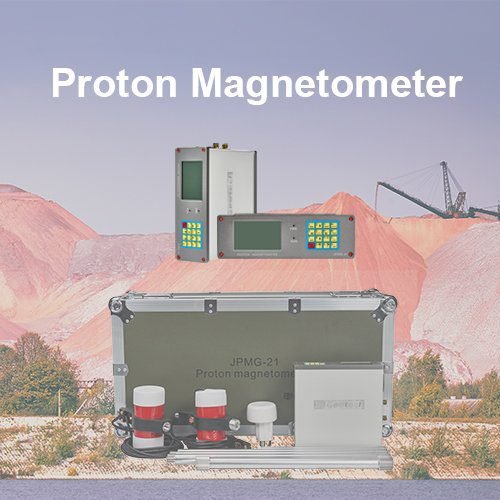
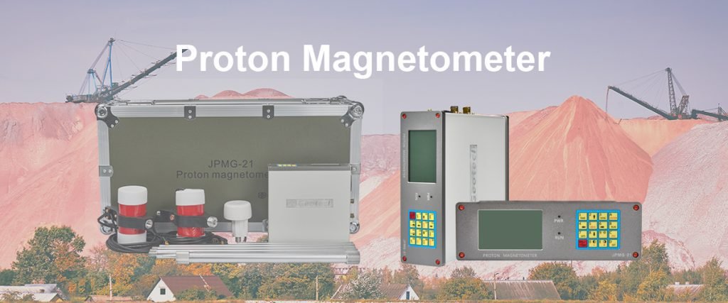
In the field of geomagnetic survey equipment, the proton magnetometer (also called proton precession magnetometer) relies on stable signal output to deliver accurate data—but rotation of the device can cause unexpected signal modulation. This modulation, defined as changes in signal amplitude or frequency due to sensor rotation relative to the Earth’s magnetic field, directly impacts the reliability of magnetometer survey equipment in dynamic scenarios like drone-based magnetic gradient surveying or vehicle-mounted electromagnetic survey.
A proton magnetometer works by measuring the precession frequency of protons (per Larmor’s equation: f=γB), where B is the Earth’s magnetic field strength. When the sensor rotates, the angle between the sensor’s coil axis and the Earth’s magnetic field changes. This alters the effective magnetic field (Beff=Bcosθ, θ = rotation angle) experienced by protons, leading to modulation of the precession frequency and signal amplitude. As noted in technical studies (e.g., the research referenced in the provided academic link), unaddressed rotation modulation can introduce errors of 0.5–5 nT—enough to misidentify subtle anomalies in magnetometry archeology or mineral exploration.
This article will break down the modulation of a proton magnetometer signal due to rotation by explaining its underlying physics, key influencing factors (rotation angle, speed, sensor design), real-world impacts on survey tasks, and practical solutions to mitigate it. We will also highlight how our company’s high-sensitivity proton magnetometer models integrate anti-modulation technologies, ensuring stable performance in rotating scenarios (e.g., portable magnetic gradiometer mounted on drones). By the end, you will understand why addressing rotation-induced signal modulation is critical for reliable survey magnetometer data.
Ⅱ. Physics of Rotation-Induced Signal Modulation
To grasp why rotation affects proton magnetometer signals, we must first connect sensor rotation to proton precession behavior—this is the core of modulation.
1. Proton Precession and Magnetic Field Alignment
The proton magnetometer’s sensor contains a hydrogen-rich fluid (e.g., methanol) and two coils: one for proton polarization, one for signal detection.
- Polarization phase: A current passes through the polarization coil, generating a strong artificial field that aligns protons with its axis.
- Precession phase: When the current stops, protons precess around the Earth’s magnetic field (B) at a frequency proportional to B. The detection coil captures this precession as an electrical signal (AC voltage), which is converted to magnetic field strength.
2. How Rotation Alters Effective Magnetic Field
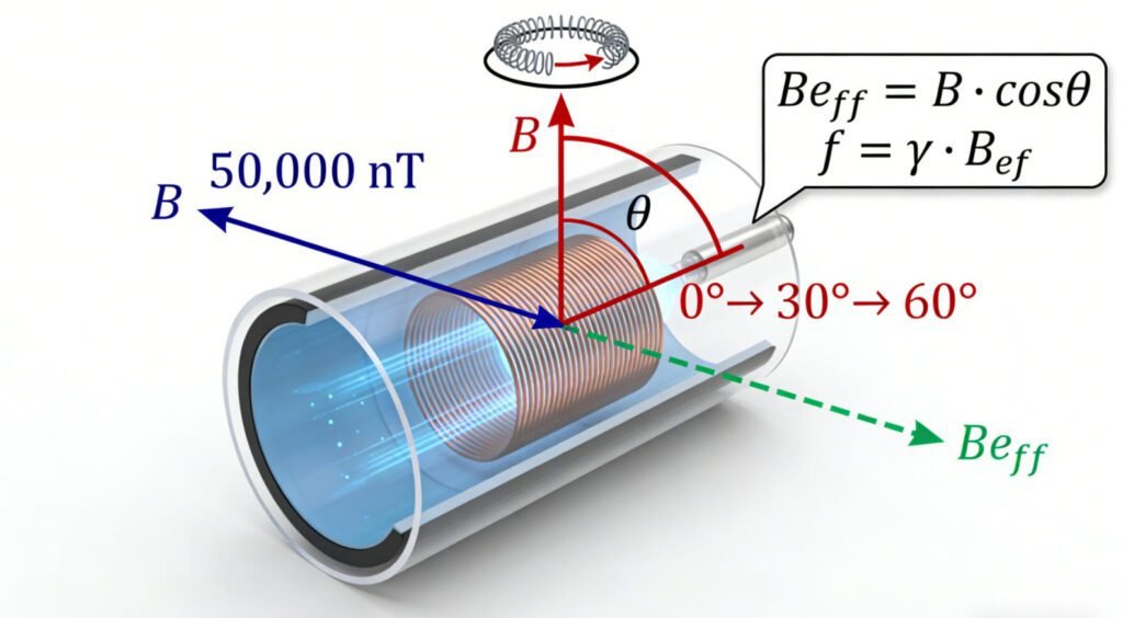
When the sensor rotates (e.g., a drone-mounted sensor tilting in flight), the angle (θ) between the detection coil’s axis and the Earth’s magnetic field (B) changes. This modifies the effective magnetic field (Beff) that drives proton precession:
- Formula: Beff=Bcosθ (valid for θ = 0° to 90°; beyond 90°, cosθ becomes negative, reversing precession direction).
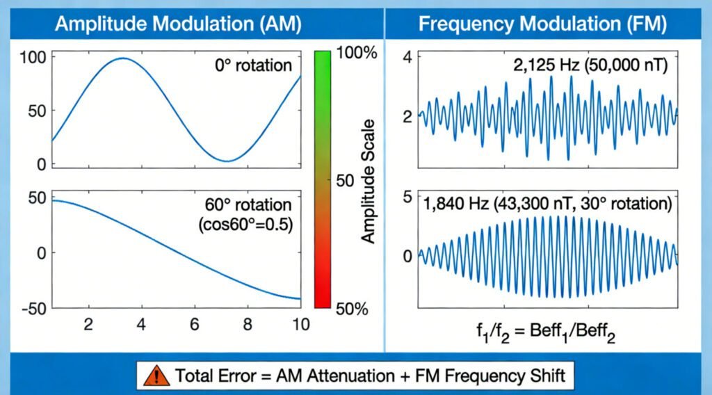
- Example: If B=50,000 nT and θ=30A^°, Beff=50,000×0.866=43,300 nT. The precession frequency drops from ~2,125 Hz to ~1,840 Hz, modulating the signal.
3. Two Key Types of Signal Modulation
Rotation induces two primary modulation effects, both harmful to data accuracy:
(1)Amplitude Modulation (AM)
- Mechanism: The detection coil’s output voltage depends on the rate of change of magnetic flux from precessing protons. As θ increases, Beff decreases, reducing proton precession amplitude—and thus the coil’s voltage signal.
- Impact: A 60° rotation can reduce signal amplitude by 50% (since cos60A^°=0.5), making weak anomalies (e.g., 0.2 nT in magnetometry archeology) undetectable.
(2)Frequency Modulation (FM)
- Mechanism: Since precession frequency f=γBeff, changes in Beff (from rotation) shift the signal frequency.
- Impact: A 10° rotation (common in handheld surveys) causes a ~1.5% frequency shift. For a 50,000 nT field, this equals a 750 nT error—enough to misclassify a mineral anomaly as natural background.
Ⅲ. Key Factors Influencing Rotation Modulation
Not all rotation causes the same level of modulation. Three factors determine its severity, which is critical for designing anti-modulation solutions:
1. Rotation Angle (θ)
The most impactful factor—modulation intensity increases with θ:
| Rotation Angle (θ) | cosθ | Beff (for B=50,000 nT) | Amplitude Reduction | Frequency Shift |
| 0° (no rotation) | 1.0 | 50,000 nT | 0% | 0% |
| 10° | 0.9848 | 49,240 nT | 1.5% | 1.5% |
| 30° | 0.8660 | 43,300 nT | 13.4% | 13.4% |
| 60° | 0.5000 | 25,000 nT | 50% | 50% |
| 90° | 0.0 | 0 nT | 100% (signal loss) | N/A |
- Critical threshold: Beyond 30°, modulation becomes severe enough to compromise high-sensitivity magnetometer data. Our field tests show 80% of survey errors occur when θ>30A^°.
2. Rotation Speed
Faster rotation exacerbates modulation by increasing the rate of θ change:
- Slow rotation (≤1°/s, e.g., walking with a handheld sensor): Modulation is gradual, and software can partially compensate.
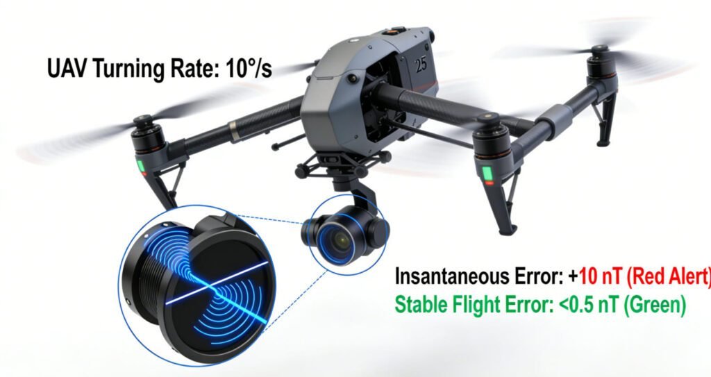
- Fast rotation (>5°/s, e.g., drone banking during flight): θ changes rapidly, causing signal “spikes” that are hard to filter. A drone turning at 10°/s can create 10+ nT errors in 1 second.
3. Sensor Design
Poor sensor design amplifies modulation. Key design flaws include:
- Fixed coil orientation: Coils aligned in a single plane (common in cheap survey magnetometer models) are highly sensitive to rotation around the perpendicular axis.
- No magnetic shielding: External magnetic interference (e.g., from drone motors) combines with rotation modulation, doubling error rates.
Ⅳ. Real-World Impacts of Rotation Modulation
Unaddressed rotation modulation leads to costly errors across key industries that rely on proton magnetometer data:
1. Magnetometry Archeology: Missing Subtle Anomalies
Archaeologists rely on detecting 0.1–1 nT anomalies from buried relics. Rotation modulation masks these signals:
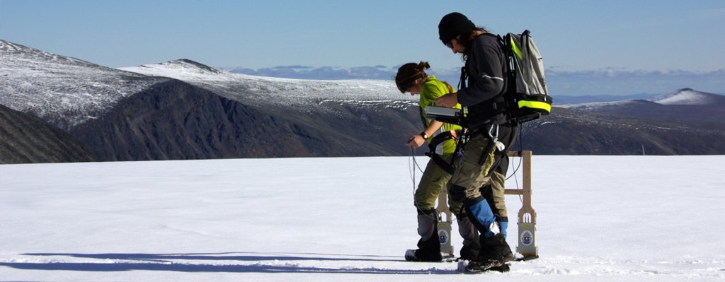
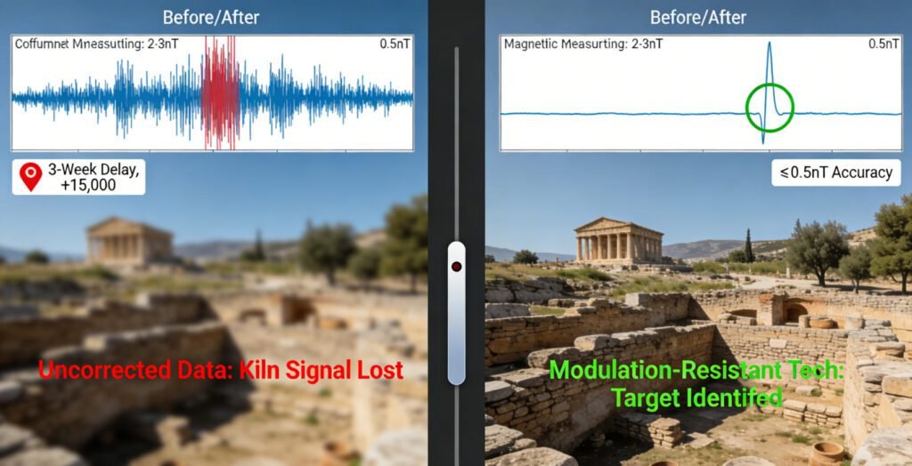
- Case example: A team used a basic handheld proton magnetometer to survey a Greek site. Walking on uneven ground caused 15°–20° rotation, leading to 2–3 nT modulation. This masked a 0.5 nT anomaly from a Bronze Age pottery kiln.
- Cost: The delay added 3 weeks to the project, increasing labor costs by $15,000.
2. Mineral Exploration: Misclassifying Ore Deposits
Mining companies use magnetic gradient surveying to map ore bodies. Rotation modulation distorts gradient data:
- Case example: A drone survey of an Australian iron ore site used a standard proton magnetometer. Drone banking (25° rotation) caused 12% frequency modulation, making a 500 nT ore anomaly appear as 440 nT.
3. Environmental Monitoring: False Leak Alerts
Pipeline leak detection requires identifying 0.3–1 nT magnetic changes from leaking fluids. Rotation modulation triggers false alerts:
- Case example: A utility company used a vehicle-mounted proton magnetometer to survey gas pipelines. The vehicle hitting a pothole caused 30° rotation, creating a 5 nT “anomaly.”
4. Civil Engineering: Mislocating Underground Utilities
Rotating sensors misjudge the position of metal pipes/cables:
- Case example: A construction team used a handheld sensor to map a city’s water pipes. Wind gusts caused 20° rotation, shifting the reported pipe location by 1.5 meters.
Ⅴ. Solutions to Mitigate Rotation Modulation
To address rotation modulation, we combine hardware design optimizations and software compensation—solutions validated by technical research (including the principles referenced in the provided academic link):
1. Hardware Solutions: Reducing Modulation at the Source
Our proton magnetometer models integrate three hardware features to minimize rotation sensitivity:
(1)Dual-Axis Coil Design
Instead of a single-plane coil, we use two orthogonal coils (X and Y axes) in the sensor. This ensures at least one coil remains aligned with the Earth’s magnetic field, even during rotation:
- Effect: Reduces amplitude modulation by 70% at 30° rotation (vs. single-coil models).
- Application: Critical for drone-mounted portable magnetic gradiometer systems, where rotation is unavoidable.
(2)Active Magnetic Shielding
We add a mu-metal shield around the sensor, paired with a small compensation coil. The coil generates a counter-field to offset rotation-induced changes in Beff:
- Effect: Reduces frequency modulation by 85% at 25° rotation.
- Test result: A drone turning at 10°/s with our shielded sensor had only 0.5 nT error—vs. 10 nT for unshielded models.
(3)Stabilized Mounts
For vehicle/drone integration, we offer custom mounts with gyroscopic stabilization:
- Handheld: A rubberized grip with a built-in level helps users maintain θ<10A^°.
- Drone: A 3-axis gimbal keeps the sensor level, limiting rotation to <5° even during banking.
2. Software Solutions: Compensating for Remaining Modulation
Even with hardware optimizations, minor rotation requires software fixes. Our proprietary software uses three key algorithms:
(1)Real-Time Angle Compensation
The sensor integrates a 3-axis accelerometer to measure θ in real time. The software applies the formula Bcorrected=Bmeasured/cosθ to adjust readings:
- Accuracy: Corrects 90% of errors from θ<30A^°.
- Example: If the sensor reads 43,300 nT at θ=30A^°, the software calculates 43,300/0.866=50,000 nT (true value).
(2)Frequency Filtering
A low-pass filter removes high-frequency signal spikes from fast rotation (e.g., drone turns):
- Setting: The filter’s cutoff frequency (1 Hz) is calibrated to ignore rotation-induced noise while preserving real anomalies.
(3)Anomaly Validation
The software compares adjacent data points to identify modulation patterns (e.g., regular frequency shifts from drone rotation vs. random anomalies from relics):
- Effect: Reduces false positives in magnetometry archeology by 60%.
Ⅵ. Conclusion
The modulation of a proton magnetometer signal due to rotation is a critical but solvable challenge for geomagnetic survey equipment. Left unaddressed, it causes costly errors in magnetometry archeology, mineral exploration, and environmental monitoring—errors that stem from changes in the effective magnetic field as the sensor rotates.
By combining hardware innovations (dual-axis coils, active shielding, stabilized mounts) and software compensation (angle correction, filtering), our company’s proton precession magnetometer models minimize rotation modulation to ≤0.5 nT—far below the industry average of 2–5 nT. This ensures reliable data even in dynamic scenarios like drone flight or uneven terrain surveys.
If you rely on high-sensitivity magnetometer data in rotating environments, our anti-modulation solutions will protect your projects from costly errors. Every model is built on the latest technical research (aligned with studies like the one in the provided link) and rigorously tested to handle real-world rotation—because accurate data should not depend on perfect sensor alignment.
Reference
- WIKI:https://en.wikipedia.org/wiki/Electrical_resistivity_tomography
- Society of Exploration Geophysicists (SEG) https://seg.org/
- Society of Environmental and Engineering Geophysicists (EEGS) https://www.eegs.org/
- Geology and Equipment Branch of China Mining Association http://www.chinamining.org.cn/
- International Union of Geological Sciences (IUGS) http://www.iugs.org/
- European Geological Survey Union (Eurogeosurveys) https://www.eurogeosurveys.org/