Welcome to Geotech!
-1.png)


Magnetometer Basics: The Cornerstone of Magnetic Field Measurement
OVerview:A Proton Magnetometer is a geophysical instrument that measures the total intensity of a magnetic field by detecting the precession frequency of hydrogen protons. Also known as a Proton Precession Magnetometer, it is used in mineral exploration, geological mapping, archaeological investigations, and selected environmental and engineering surveys. Understanding its operating principle, measurement capabilities, and limitations helps survey professionals select suitable magnetic survey equipment and obtain reliable field data.
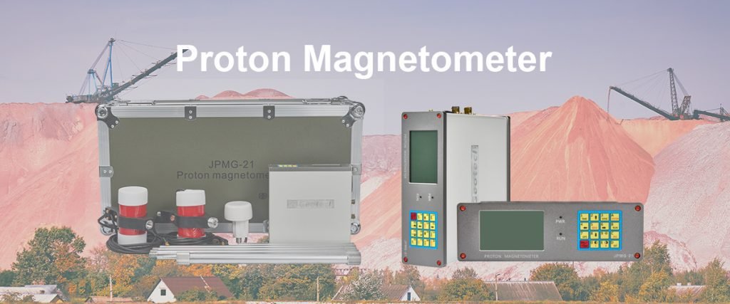
I. What Is a Proton Magnetometer?
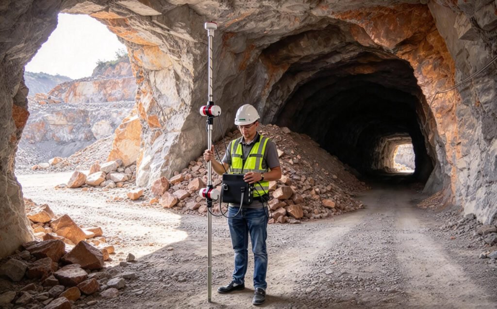
A proton magnetometer is a magnetic field measurement instrument that determines the magnitude of the ambient magnetic field by measuring the precession frequency of protons in a hydrogen-rich medium.
It is commonly known as a proton precession magnetometer (PPM). The instrument uses the relationship between proton precession frequency and magnetic field strength to calculate the total magnetic field intensity.
Unlike a vector magnetometer, which measures individual magnetic field components, a conventional proton precession magnetometer provides a scalar measurement of the total field.
This makes it useful for magnetic surveys where the spatial variation of total magnetic field intensity is the primary measurement objective.
1. What Does a Proton Magnetometer Measure?
A proton magnetometer measures the total magnetic field magnitude, commonly represented by (F) or (B).
The total field can be expressed as:
[
F=\sqrt{X^2+Y^2+Z^2}
]
Where:
- (X) is the northward component of the magnetic field.
- (Y) is the eastward component.
- (Z) is the vertical component.
A proton magnetometer does not independently provide these three components. It measures the scalar magnitude of the combined field.
2. Proton Magnetometer vs. General Magnetometer
A magnetometer is a broad category of instruments used to measure magnetic fields. Different magnetometer technologies measure different physical quantities and serve different applications.
| Instrument Type | Measurement Output | Typical Applications |
|---|---|---|
| Proton precession magnetometer | Total magnetic field magnitude | Ground magnetic surveys and geomagnetic measurements |
| Overhauser magnetometer | Total magnetic field magnitude | High-sensitivity magnetic surveys and monitoring |
| Fluxgate magnetometer | Magnetic field vector components | Directional magnetic measurements and observatory systems |
| Optically pumped magnetometer | Scalar or vector output depending on design | High-resolution magnetic surveys and specialized applications |
| Hall-effect magnetometer | Magnetic field component or magnitude depending on configuration | Industrial sensing and magnetic field testing |
The choice depends on the required measurement output, sampling rate, field conditions, and survey objectives.
II. How Does a Proton Precession Magnetometer Work?
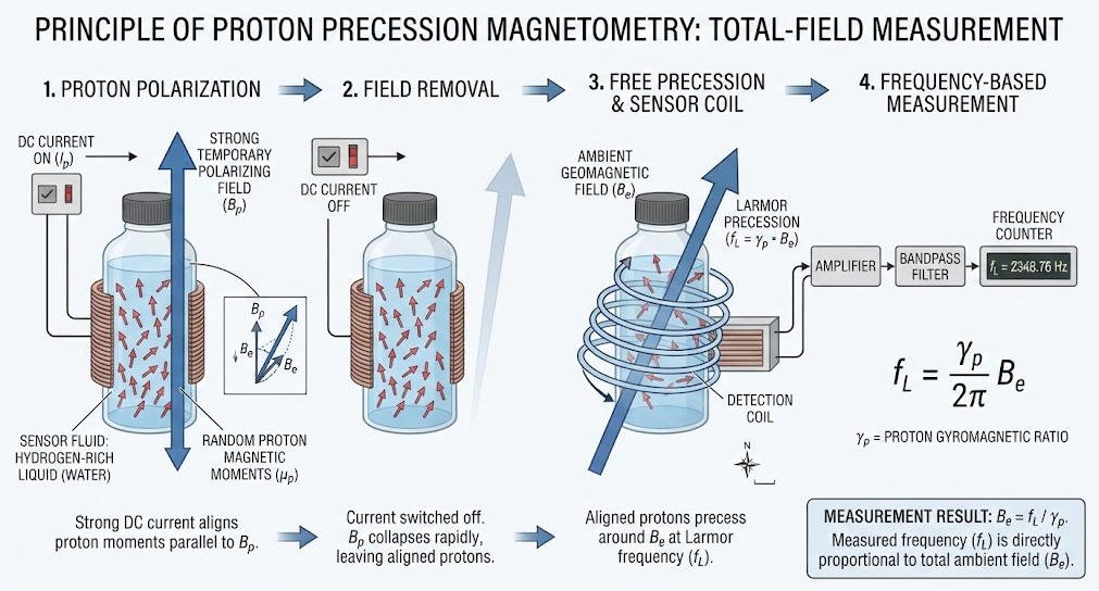
A proton precession magnetometer uses the magnetic properties of hydrogen nuclei to determine the ambient magnetic field strength.
Its operation generally involves four stages: polarization, free precession, signal detection, and frequency estimation.
1. Proton Polarization
The sensor contains a hydrogen-rich liquid, such as a suitable hydrocarbon fluid or another hydrogen-containing medium.
During polarization, an electrical current generates a temporary magnetic field around the sensor. This field partially aligns the proton magnetization.
The polarization field is then switched off, allowing the proton magnetization to evolve under the influence of the ambient magnetic field.
2. Free Precession
After the polarization field is removed, the proton magnetization precesses around the ambient magnetic field direction.
The ideal Larmor frequency is:
[
f=\frac{\gamma_p}{2\pi}B
]
Where:
- (f) is the proton precession frequency.
- (\gamma_p) is the proton gyromagnetic ratio.
- (B) is the ambient magnetic field magnitude.
For protons:
[
\frac{\gamma_p}{2\pi}\approx42.577\ \text{MHz/T}
]
The precession frequency is proportional to the magnetic field magnitude.
3. Signal Detection
The precessing proton magnetization generates a changing magnetic flux through the sensor coil, inducing a weak electrical signal.
The signal is typically a damped oscillation. Its amplitude decreases over time as the proton ensemble loses phase coherence.
The instrument amplifies and processes this signal to estimate its frequency.
4. Magnetic Field Calculation
Once the precession frequency is estimated, the instrument calculates the magnetic field magnitude:
[
B=\frac{2\pi f}{\gamma_p}
]
This frequency-based measurement provides a direct way to determine the total magnetic field intensity.
For more detail, see the Geotech guide on proton magnetometer measurement principles.
III. Main Components of a Proton Magnetometer
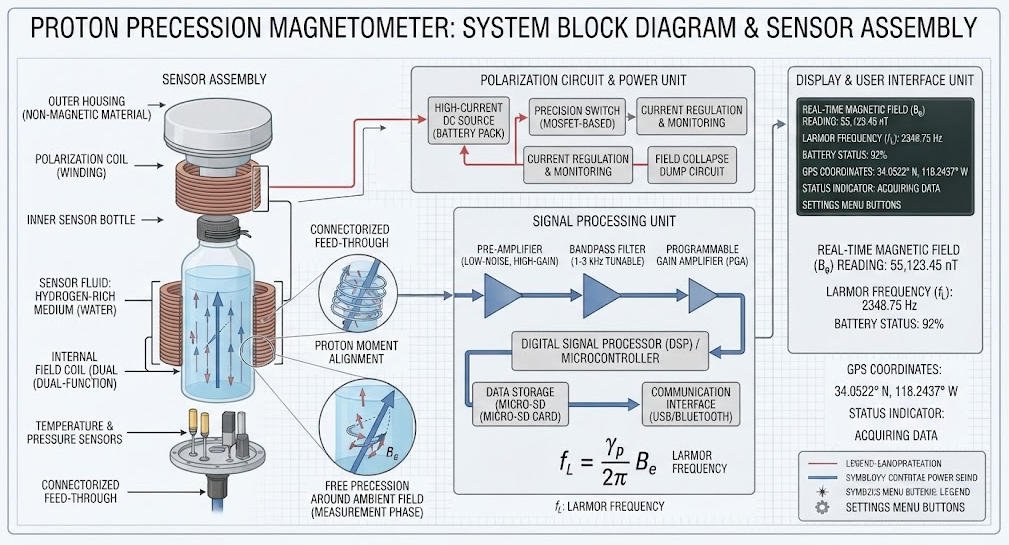
A proton magnetometer typically includes a sensor assembly, polarization circuit, signal detection electronics, frequency-processing unit, and data display or recording system.
1. Sensor Assembly
The sensor contains the hydrogen-rich medium and coil system used for polarization and signal detection.
Sensor design influences signal strength, measurement repeatability, and operating characteristics.
2. Polarization Circuit
The polarization circuit supplies current to generate the temporary magnetic field required to establish proton magnetization.
The duration and stability of the polarization phase affect the measurement cycle.
3. Signal Detection and Amplification
The detection circuit receives the weak precession signal and amplifies it for processing.
Because the signal may be small, electrical noise and nearby magnetic interference can affect measurement reliability.
4. Frequency Processing Unit
The processing unit estimates the precession frequency and converts it into a magnetic field value.
Depending on the instrument, processing may involve filtering, signal conditioning, frequency counting, or digital estimation.
5. Data Display and Recording
The instrument displays or records the calculated magnetic field intensity.
Survey systems may also support data storage, positioning information, time synchronization, and data transfer, depending on their configuration.
Table 1. Main Components and Their Functions
| Component | Primary Function | Key Consideration |
|---|---|---|
| Sensor assembly | Generates and detects proton precession signals | Sensor geometry and signal strength |
| Polarization circuit | Creates the temporary polarization field | Polarization stability and cycle duration |
| Signal detection circuit | Receives and amplifies the signal | Noise and interference control |
| Frequency processor | Estimates frequency and calculates field strength | Frequency-estimation reliability |
| Display and data system | Presents and records measurements | Data integrity and workflow compatibility |
IV. Advantages and Limitations of Proton Magnetometers
Proton magnetometers offer useful characteristics for total-field magnetic surveys, but their suitability depends on the measurement environment.
1. Key Advantages
Scalar total-field measurement: The instrument measures the magnitude of the magnetic field rather than an individual directional component.
Frequency-based measurement: The field value is derived from the proton precession frequency, which is related to a fundamental physical constant.
Field survey capability: Portable configurations can support ground-based magnetic mapping and geological investigations.
Repeatable measurement under suitable conditions: Consistent sensor placement, stable magnetic conditions, and reliable signal detection help support repeatable readings.
2. Practical Limitations
Proton magnetometers also have limitations that should be considered before equipment selection.
- Measurement cycle: Conventional proton precession instruments require a polarization and signal-acquisition cycle. Their sampling rate may be lower than that of some continuous-reading technologies.
- Signal strength: The precession signal is weak and can be affected by electrical noise or magnetic interference.
- Magnetic field gradients: Strong spatial gradients may degrade the signal or make measurements difficult, depending on sensor design.
- Dynamic measurement: Rapid movement during acquisition may affect measurement quality.
- Directional information: A conventional scalar proton magnetometer does not directly measure the individual vector components of the magnetic field.
Table 2. Advantages and Limitations
| Characteristic | Benefit | Limitation |
|---|---|---|
| Scalar measurement | Provides total field intensity | Does not independently provide vector components |
| Frequency-based principle | Links measured frequency to magnetic field magnitude | Requires reliable signal detection and frequency estimation |
| Portable configurations | Supports field-based surveys | Field logistics and measurement cycle remain important |
| Repeatable readings | Supports consistent surveys under controlled conditions | External interference and inconsistent procedures can affect results |
| High-gradient capability | Some designs support challenging gradient environments | Tolerance is instrument-specific and should be verified |
V. Applications of Proton Magnetometers
Proton magnetometers are used in geophysical and scientific applications where total magnetic field intensity is an important measurement.
The instrument does not directly identify a buried object or geological structure. Instead, it records magnetic field variations that may be interpreted alongside geological information and other survey data.
1. Mineral Exploration
Magnetic surveys are widely used in mineral exploration to map magnetic variations associated with geological structures and magnetic minerals.
A proton magnetometer can help measure total-field anomalies that may be associated with:
- Magnetite-bearing formations.
- Magnetic igneous rocks.
- Geological contacts.
- Structural features affecting magnetic properties.
- Selected mineralization systems with magnetic signatures.
Not all mineral deposits produce detectable magnetic anomalies. Interpretation requires geological context and, where appropriate, complementary geophysical methods.
2. Geological Mapping
Magnetic measurements can help identify contrasts in magnetic susceptibility and remanent magnetization between geological units.
Survey data may support the mapping of:
- Lithological boundaries.
- Faults and structural trends.
- Intrusive bodies.
- Variations in magnetic basement depth, when supported by suitable interpretation methods.
The magnetometer provides magnetic field measurements; geological interpretation requires additional information and analysis.
3. Archaeological Surveys
Archaeological magnetometry uses variations in magnetic properties to investigate buried features.
Depending on the site and target, magnetic surveys may help identify anomalies associated with:
- Fired materials and kilns.
- Ditches and pits.
- Buried walls or foundations.
- Disturbed soils.
- Certain archaeological structures with magnetic contrasts.
The detectability of a target depends on its magnetic properties, depth, size, orientation, and the background magnetic environment.
A magnetic anomaly alone does not confirm the presence or identity of an archaeological feature.
4. Environmental and Engineering Surveys
Magnetic surveys can support selected environmental and engineering investigations.
Potential targets include:
- Buried ferrous objects.
- Certain buried infrastructure with magnetic signatures.
- Ferrous waste and metallic debris.
- Magnetic geological features relevant to site characterization.
A proton magnetometer does not directly detect non-magnetic contaminants or reliably locate every type of underground utility. Project design should consider target material, depth, expected magnetic contrast, and interference.
5. Geomagnetic Monitoring
Proton magnetometers can measure total magnetic field intensity at fixed locations.
When combined with suitable reference instruments and monitoring procedures, they can contribute to studies of temporal magnetic field variations.
Long-term monitoring requires careful site selection, stable installation, interference control, and consistent data processing.
Table 3. Applications and Survey Considerations
| Application | Measurement Objective | Important Considerations |
|---|---|---|
| Mineral exploration | Map magnetic anomalies related to geology | Magnetic properties of the target and geological context |
| Geological mapping | Identify magnetic contrasts between units | Regional field, geology, and survey spacing |
| Archaeology | Detect magnetic contrasts associated with buried features | Target depth, soil conditions, and background noise |
| Environmental investigation | Locate selected ferrous targets and magnetic features | Target composition and nearby metallic interference |
| Engineering surveys | Support investigation of magnetic structures or objects | Complementary methods may be required |
| Geomagnetic monitoring | Record total-field variation over time | Stable installation and reference measurements |
VI. Proton Magnetometer in Magnetic Gradient Surveys
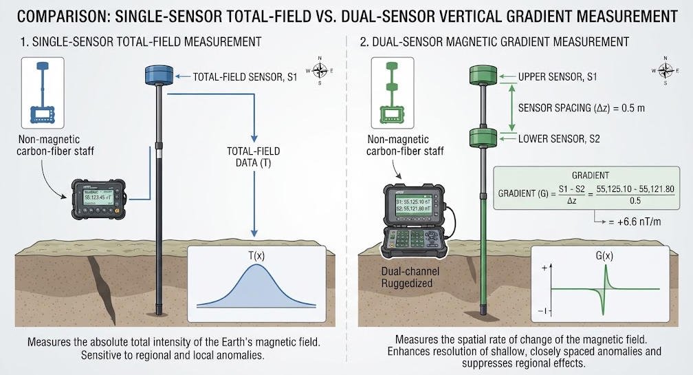
A magnetic gradient survey measures the spatial change in magnetic field intensity between two or more positions.
Gradient measurements can help emphasize shallow or localized magnetic sources and reduce some common-mode variations, depending on the survey design.
1. Basic Gradient Calculation
For two sensors separated by a known distance:
[
G=\frac{B_2-B_1}{d}
]
Where:
- (G) is the estimated magnetic gradient along the sensor separation direction.
- (B_1) and (B_2) are the measured total-field values.
- (d) is the sensor separation distance.
The equation assumes that the sensor positions and measurement timing are appropriately controlled.
2. Single-Sensor vs. Dual-Sensor Configurations
A single-sensor proton magnetometer measures the total field at one location at a time.
A dual-sensor configuration measures the field at two sensor positions. Depending on the instrument design, synchronization, and geometry, the two measurements can be used to estimate a magnetic gradient.
3. Key Considerations
When using a proton magnetometer for gradient surveys, engineers should evaluate:
- Sensor separation and alignment.
- Measurement timing and synchronization.
- Differences in sensor response.
- Platform motion and sensor orientation.
- Local magnetic interference.
- Data processing and gradient calculation methods.
Table 4. Single-Sensor vs. Dual-Sensor Proton Magnetometers
| Feature | Single-Sensor Configuration | Dual-Sensor Configuration |
|---|---|---|
| Measurement | Total field at one sensor position | Total field at two sensor positions |
| Main use | Magnetic mapping and point measurements | Differential measurements and selected gradient surveys |
| Setup | One sensor assembly | Two sensors with defined geometry |
| Data processing | Total-field processing | Requires channel alignment and gradient calculation |
| Main consideration | Survey spacing and repeatability | Sensor spacing, synchronization, and channel consistency |
VII. Proton Magnetometer vs. Other Magnetic Survey Technologies
Different magnetic sensor technologies provide different measurement capabilities.
1. Proton Precession Magnetometer vs. Fluxgate Magnetometer
A proton precession magnetometer measures the total magnetic field magnitude.
A fluxgate magnetometer measures magnetic field components along its sensor axes.
The two technologies are complementary rather than interchangeable in every application.
2. Proton Magnetometer vs. Overhauser Magnetometer
Both technologies can measure total magnetic field intensity.
Overhauser magnetometers use a different physical process and may support faster measurement cycles in suitable configurations.
The choice depends on required sampling rate, sensitivity, operating conditions, and survey design.
3. Proton Magnetometer vs. Optically Pumped Magnetometer
Optically pumped magnetometers use atomic vapor and optical methods to measure magnetic fields.
Depending on the instrument, they may support high-sensitivity or continuous measurement applications.
Their operating requirements and motion response differ from those of proton precession systems.
Table 5. Technology Comparison
| Technology | Output | Typical Strength | Main Consideration |
|---|---|---|---|
| Proton precession magnetometer | Total field magnitude | Scalar field measurement | Measurement cycle and signal conditions |
| Overhauser magnetometer | Total field magnitude | High-sensitivity total-field measurement | Instrument-specific operating conditions |
| Fluxgate magnetometer | Vector components | Directional field measurement | Axis alignment and calibration |
| Optically pumped magnetometer | Scalar or vector output depending on design | High-sensitivity and specialized measurement | Sensor-specific operating requirements |
VIII. How to Choose the Right Proton Magnetometer
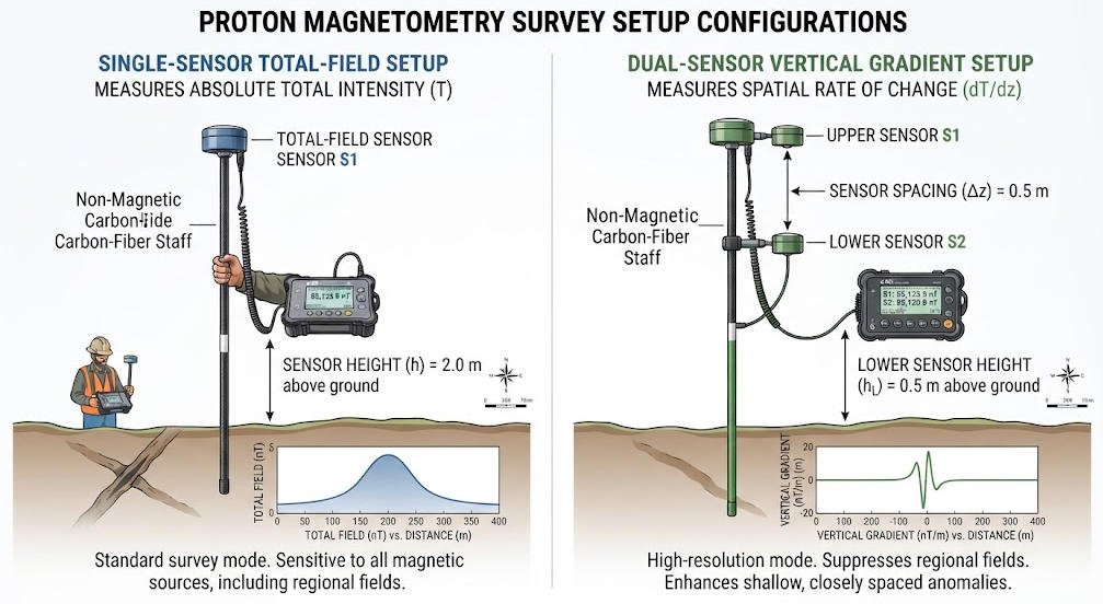
Selecting a proton magnetometer requires matching the instrument’s capabilities to the survey’s measurement objectives and field conditions.
1. Define the Survey Objective
Before selecting equipment, determine:
- Whether total-field or gradient data are required.
- The expected magnetic anomaly amplitude.
- The survey area and geological environment.
- The required spatial resolution.
- Whether the work is stationary, walking, vehicle-mounted, or conducted from another platform.
2. Evaluate Key Technical Parameters
| Parameter | Why It Matters |
|---|---|
| Sensitivity | Indicates the instrument’s ability to respond to small field changes under defined conditions |
| Resolution | Indicates the smallest displayed or reported increment |
| Accuracy | Describes closeness to a reference value under specified conditions |
| Measurement cycle | Determines how frequently valid measurements can be acquired |
| Gradient tolerance | Relevant in areas with strong spatial field changes |
| Dynamic range | Defines the field interval the instrument can measure |
| Environmental protection | Determines suitability for outdoor operating conditions |
| Data output | Affects compatibility with survey and processing workflows |
| Positioning and timing | Important for mobile and multi-sensor surveys |
Sensitivity, resolution, and accuracy are different specifications. They should not be treated as interchangeable when comparing equipment.
3. Consider Field Conditions
The local environment can strongly influence measurement quality.
Before field deployment, assess:
- Nearby power lines and electrical equipment.
- Ferrous structures, vehicles, and metallic objects.
- Local magnetic field gradients.
- Terrain and sensor positioning.
- Temperature and weather conditions.
- Operator workflow and data recording requirements.
4. Check Data Compatibility
A survey instrument should fit the complete data workflow.
Confirm whether the system supports the required data formats, positioning information, time synchronization, and processing software.
For multi-sensor work, verify that the system provides sufficient information to align measurements correctly.
IX. Geotech Proton Magnetometer Solutions
Geotech provides magnetic exploration instruments for geophysical fieldwork, including single-sensor and dual-sensor proton magnetometer configurations.
The appropriate configuration depends on the survey objective, required measurement cycle, sensor arrangement, environmental conditions, and data-processing workflow.
1. Single-Sensor Proton Magnetometer
A single-sensor proton magnetometer is designed for total-field measurements at individual survey points.
Potential applications include:
- Ground magnetic mapping.
- Geological magnetic surveys.
- Reference measurements.
- Selected geomagnetic monitoring tasks.
For current specifications and configuration details, visit the Geotech Single-Sensor Proton Magnetometer.
2. Dual-Sensor Proton Magnetometer
A dual-sensor proton magnetometer measures magnetic field intensity at two sensor positions.
Depending on sensor spacing, synchronization, and system design, the two measurements may be used for gradient estimation.
For current product information, visit the Geotech Dual-Sensor Proton Magnetometer.
3. Magnetic Instrument Portfolio
Explore the complete Geotech Magnetic Instrument Portfolio to review available magnetic survey equipment and configurations.
Before selecting a product, confirm the current specifications, supported measurement modes, environmental limits, and intended application with the manufacturer.
X. Common Mistakes When Using Proton Magnetometers
1. Confusing Total-Field Measurement With Vector Measurement
A conventional proton precession magnetometer measures the total magnetic field magnitude, not independent directional components.
If directional data are required, a vector magnetometer or a suitable combined measurement system may be necessary.
2. Assuming Every Magnetic Anomaly Indicates Mineralization
Magnetic anomalies can result from many sources, including geological structures, magnetic minerals, cultural objects, and man-made interference.
Anomaly interpretation should be supported by geological information and complementary measurements where appropriate.
3. Treating Sensitivity as Accuracy
Sensitivity, resolution, and accuracy describe different instrument characteristics.
A high sensitivity value alone does not guarantee that every field measurement will achieve the same accuracy.
4. Ignoring Magnetic Interference
Nearby ferrous materials, electrical equipment, and magnetic structures can distort survey measurements.
Survey planning should include an assessment of potential interference sources.
5. Selecting Equipment Without Considering the Measurement Cycle
A conventional proton precession instrument requires a measurement cycle.
If the project needs rapid continuous sampling, a different sensor technology may be more appropriate.
XI. Conclusion
A proton magnetometer is a valuable instrument for measuring total magnetic field intensity in geophysical surveys and selected scientific applications.
Its frequency-based measurement principle supports magnetic mapping, geological investigation, archaeological surveys, and geomagnetic monitoring. However, its performance depends on signal quality, field conditions, measurement cycle, and survey design.
Understanding the distinction between total-field and vector measurements, recognizing the limitations of magnetic anomaly interpretation, and selecting equipment based on verified specifications are essential for reliable survey results.
For professional users, the right proton magnetometer is the one that matches the target, operating environment, required data quality, and project workflow.
Related Articles
| Anchor Text | Target URL | Core Content |
|---|---|---|
| Proton Precession Magnetometer Measurement Principle | https://geotechcn.net/service/how-proton-precession-works-in-measurement/ | Proton precession physics and measurement workflow |
| Proton Magnetometer Working Principle | https://geotechcn.net/service/proton-magnetometer-from-hydrogen-atom-polarization-to-accurate-magnetic-field-measurement/ | Proton polarization and total-field measurement |
| Proton Magnetometer Signal Processing | https://geotechcn.net/service/proton-magnetometer-signal-processing/ | Signal detection, filtering, and frequency estimation |
| Proton Magnetometer Signal Modulation | https://geotechcn.net/service/modulation-of-a-proton-magnetometer-signal-due-to-rotation/ | Rotation-related signal modulation and measurement quality |
| Single-Sensor Proton Magnetometer | https://geotechcn.net/products/magnetic-instrument/proton-magnetometer-single/ | Single-sensor product configuration |
| Dual-Sensor Proton Magnetometer | https://geotechcn.net/products/magnetic-instrument/dual-sensor-proton-magnetometer/ | Dual-sensor measurement and gradient applications |
| Magnetic Instruments | https://geotechcn.net/products/magnetic-instrument/ | Magnetic exploration instrument portfolio |
Reference Sources
| Organization / Source | Reference URL | Core Content |
|---|---|---|
| U.S. Geological Survey (USGS) — Introduction to Geomagnetism | https://www.usgs.gov/programs/geomagnetism/introduction-geomagnetism | Total magnetic field intensity and geomagnetic measurement |
| U.S. Geological Survey (USGS) — Instrumentation | https://www.usgs.gov/programs/geomagnetism/science/instrumentation | Proton magnetometers and fluxgate magnetometers in observatories |
| USGS — Proton Magnetometer Technical Report | https://pubs.usgs.gov/of/1981/1346/report.pdf | Proton precession measurement principle and frequency-field relationship |
| Society of Exploration Geophysicists (SEG) | https://seg.org/ | Geophysical exploration methods and professional resources |
| European Association of Geoscientists and Engineers (EAGE) | https://www.eage.org/ | Geoscience and engineering research resources |
FAQ
Q1. What is a proton magnetometer used for?
A proton magnetometer measures total magnetic field intensity. It is used in ground magnetic surveys, mineral exploration, geological mapping, archaeological investigations, and selected monitoring applications. It records magnetic field variations that may indicate changes in geology or the presence of magnetic materials, but it does not directly identify buried targets.
Q2. How does a proton precession magnetometer work?
A proton precession magnetometer polarizes hydrogen protons using a temporary magnetic field. When the field is removed, the protons precess in the ambient magnetic field and generate a weak electrical signal. The instrument estimates the signal frequency and converts it into total magnetic field intensity using the proton gyromagnetic ratio.
Q3. What is the difference between a proton magnetometer and a fluxgate magnetometer?
A proton magnetometer measures the scalar magnitude of the total magnetic field. A fluxgate magnetometer measures magnetic field components along its sensor axes. Proton instruments are suitable for total-field surveys, while fluxgate instruments provide directional information useful for vector measurements and geomagnetic observatory systems.
Q4. Can a proton magnetometer detect underground utilities?
A proton magnetometer may help detect selected buried ferrous objects or infrastructure that produces a measurable magnetic anomaly. It cannot reliably locate every utility, especially non-magnetic pipes and cables. Utility detection requires selecting a method suited to the target material, depth, and site conditions.
Q5. What should be considered when selecting a proton magnetometer?
Key factors include sensitivity, resolution, accuracy, measurement cycle, dynamic range, gradient tolerance, environmental protection, data output, and survey objectives. The instrument should also be evaluated against local magnetic interference, required sampling rate, sensor configuration, and the intended field workflow.