Welcome to Geotech!


Resistivity Meters: Principles, Types & Selection Guide
Overview:A Resistivity Meter is a geophysical instrument used to measure the electrical response of soil, rock, and other materials. By injecting a controlled current and measuring the resulting voltage, it calculates apparent resistivity to help identify subsurface variations. Understanding how an Electrical Resistivity Meter works is essential for groundwater exploration, mineral investigation, environmental assessment, and geotechnical engineering.
Ⅰ. What Is a Resistivity Meter?
A resistivity meter is an electrical measurement instrument that determines how strongly a material opposes the flow of electric current. In geophysical exploration, it is commonly used to investigate the electrical properties of soil, rock, and subsurface formations.
Unlike a conventional resistance meter, which measures the resistance of a specific component, a geophysical resistivity meter typically injects electrical current into the ground and measures the resulting potential difference. The instrument then calculates apparent resistivity, taking electrode geometry into account.
Resistivity measurements help engineers and geoscientists identify variations in subsurface materials, assess geological structures, and support engineering decisions.
1. Resistivity vs. Resistance: What Is the Difference?
Resistance and resistivity are related but represent different physical properties.
| Parameter | Resistance | Resistivity |
|---|---|---|
| Definition | Opposition to current flow in a particular object or path | Intrinsic electrical property of a material |
| Symbol | R | ρ |
| Unit | Ohm (Ω) | Ohm-meter (Ω·m) |
| Depends on | Material, length, cross-sectional area, and geometry | Material properties and physical conditions |
| Typical use | Circuit and component testing | Material characterization and geophysical surveys |
For a uniform conductor, resistance is related to resistivity by:
R=ρAL
Where:
- R = resistance in ohms
- ρ = resistivity in ohm-meters
- L = conductor length
- A = cross-sectional area
In field geophysics, the underground is rarely uniform. Therefore, a resistivity meter usually reports apparent resistivity, rather than the true resistivity of a single geological layer.
2. What Does a Resistivity Meter Measure?
A resistivity meter measures electrical current and voltage, then uses the electrode arrangement to calculate an apparent resistivity value.
The results can help indicate variations related to:
- Soil and rock composition
- Moisture content and pore-water salinity
- Clay content and geological structure
- Fractures, weathering, and possible cavities
- Changes in groundwater conditions
Important: Resistivity is not a unique identifier of a material. Different geological materials can have similar resistivity values, so interpretation should consider site geology and, when appropriate, other geophysical methods.
Ⅱ. How Does a Resistivity Meter Work?
A geophysical resistivity meter generally operates by injecting a controlled electrical current into the ground and measuring the voltage difference between designated electrodes.
The measurement process follows Ohm’s law:
R=IV
Where:
- R = measured resistance
- V = measured potential difference
- I = injected current
Because the measured voltage depends on electrode geometry, the instrument applies a geometric factor to calculate apparent resistivity.
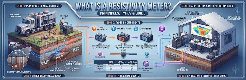
1. The Four-Electrode Measurement Principle
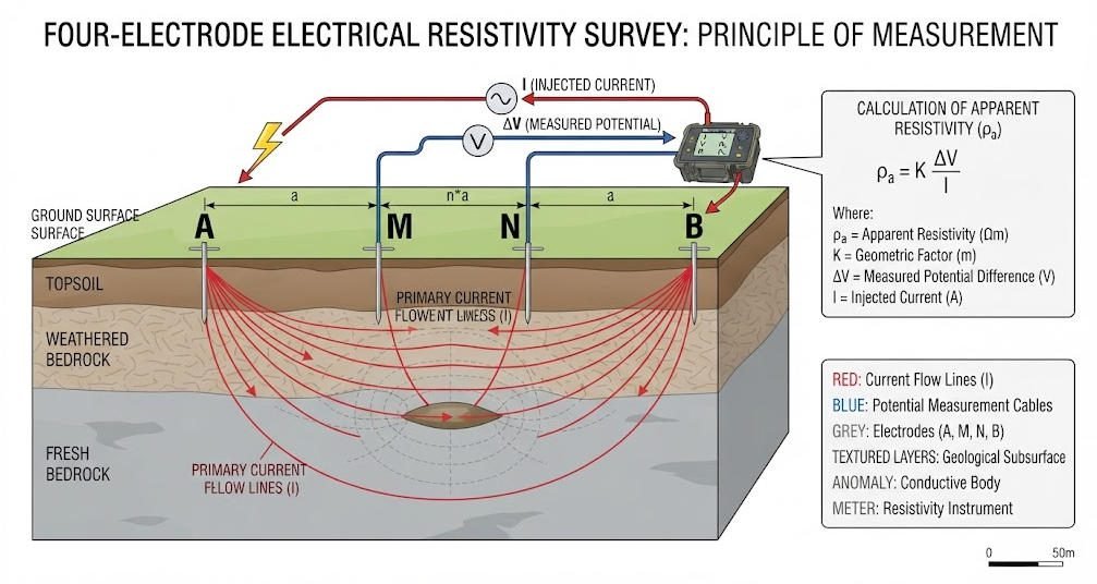
The four-electrode method is widely used in geophysical resistivity surveys. It separates current injection from voltage measurement to reduce the influence of electrode contact resistance on the potential measurement.
The four electrodes are:
- A and B: Current electrodes that inject electrical current into the ground.
- M and N: Potential electrodes that measure the voltage difference.
The meter records the current I and voltage difference ΔV, then calculates resistance:
R=IΔV
For a homogeneous half-space, apparent resistivity is calculated using:
ρa=KIΔV
Here, K is the geometric factor determined by the electrode arrangement and spacing.
2. Common Electrode Arrays
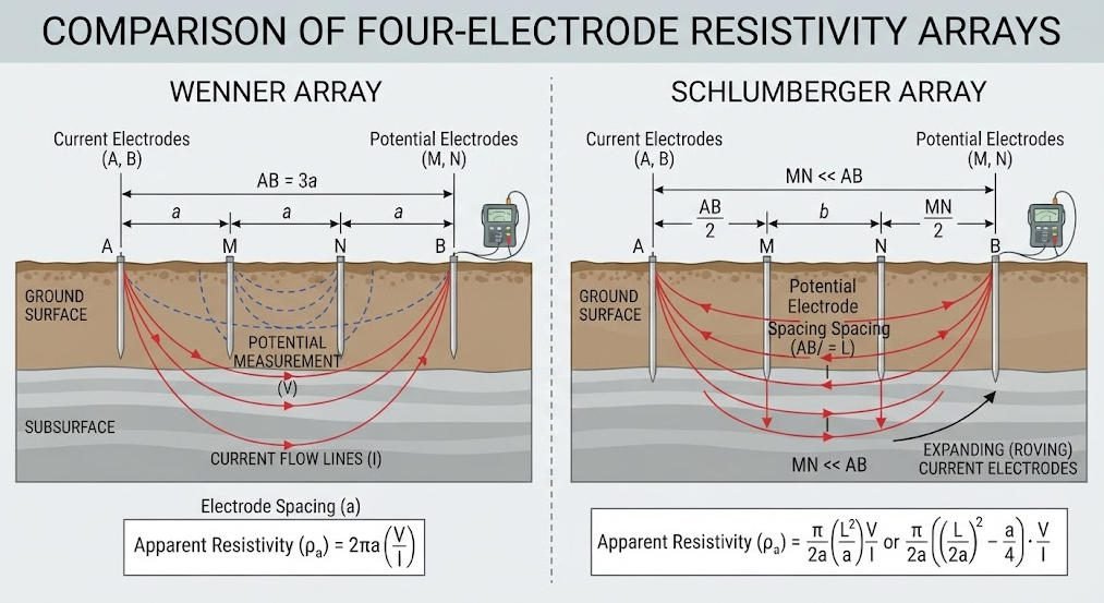
Different electrode configurations are used to meet survey objectives.
| Array | Electrode Arrangement | Typical Application |
|---|---|---|
| Wenner | Four equally spaced electrodes | General soil resistivity surveys and shallow investigations |
| Schlumberger | Current electrodes farther apart than potential electrodes | Vertical electrical sounding and layered-ground investigations |
| Dipole-Dipole | Two current electrodes and two potential electrodes arranged as dipoles | Lateral geological variations and imaging |
| Wenner-Schlumberger | Hybrid arrangement combining characteristics of Wenner and Schlumberger | 2D resistivity imaging and engineering surveys |
The choice of array affects measurement sensitivity, depth of investigation, signal strength, and survey efficiency. No single array is ideal for every geological condition.
3. From Field Measurements to Resistivity Images
In a conventional sounding survey, electrode spacing is progressively increased to investigate changes in apparent resistivity with depth.
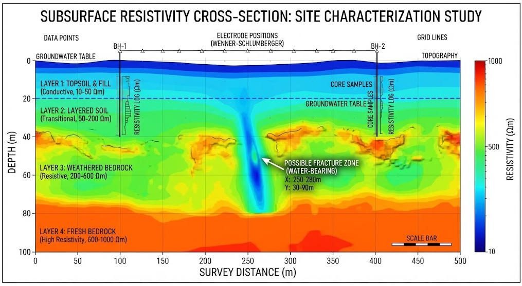
In Electrical Resistivity Tomography (ERT), multiple electrode combinations are measured along a survey line. The collected data are processed through inversion software to produce a 2D or 3D resistivity model.
The workflow is generally:
- Select the survey line and electrode configuration.
- Install electrodes and connect the cables.
- Inject current and record voltage measurements.
- Repeat measurements using different electrode combinations.
- Review data quality and remove unreliable readings when justified.
- Invert the measurements to estimate a subsurface resistivity distribution.
- Interpret the model alongside geological and site information.
The resulting image is an interpreted model, not a direct photograph of underground structures.
Ⅲ. Main Components of a Resistivity Meter
A modern geophysical resistivity meter combines electrical output, measurement, control, and data management functions.

| Component | Function |
|---|---|
| Power Supply | Provides the energy required for electrical current injection |
| Current Transmitter | Controls the injected current or output signal |
| Voltage Measurement Circuit | Measures potential differences between electrodes |
| Electrodes | Establish electrical contact with the ground |
| Electrode Cables | Connect the instrument to the electrode array |
| Control Unit | Manages measurement settings and operating procedures |
| Data Storage and Interface | Records measurements and transfers data for processing |
For multi-channel systems, switching units may also be used to control many electrodes and automate measurement sequences.
Ⅳ. Types of Resistivity Meters
Resistivity meters can be classified by measurement purpose, channel architecture, and application environment.
1. Single-Channel Resistivity Meters
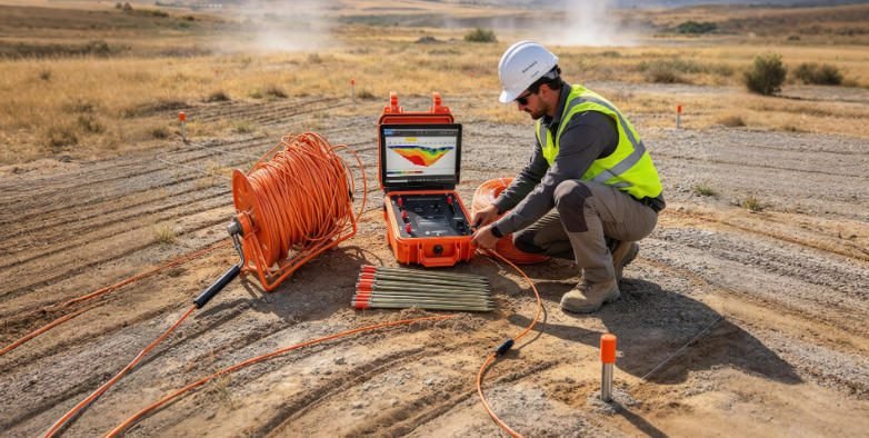
Single-channel instruments measure one electrode configuration at a time. They are commonly used for basic resistivity surveys, electrical sounding, and field investigations where manual electrode movement is practical.
Typical advantages:
- Compact and portable design
- Straightforward operation
- Suitable for basic surveys and targeted measurements
- Lower system complexity
2. Multi-Channel and High-Density Resistivity Systems
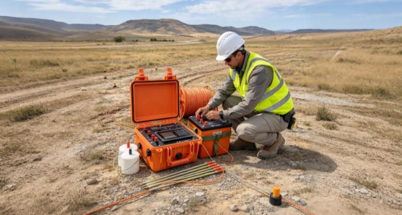
Multi-channel systems support automated or semi-automated measurements across multiple electrodes. They are frequently used for high-density resistivity surveys and ERT imaging.
Typical applications include:
- Engineering geological investigations
- Groundwater exploration
- Environmental site assessment
- Detection of subsurface anomalies
- Geological structure mapping
3. Resistivity Meters for Specialized Applications
Specialized instruments may be designed for specific measurement environments, such as borehole logging, laboratory material testing, or electrical grounding surveys.
These instruments should not be treated as interchangeable. A geophysical resistivity meter used for subsurface imaging has different measurement objectives from a ground resistance tester used to verify an electrical grounding system.
Ⅴ. What Are Resistivity Meters Used For?
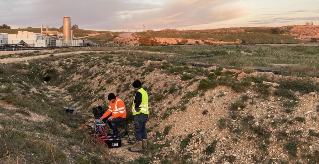
Resistivity meters are used in geophysical exploration, engineering investigation, environmental studies, and selected electrical testing applications.
1. Groundwater Exploration
Resistivity surveys help identify geological formations that may be associated with groundwater storage, including weathered zones, fractured bedrock, and saturated sediments.
However, low resistivity can also result from clay-rich formations or saline water. Resistivity data should therefore be interpreted with local geological information and, where possible, borehole data.
2. Mineral Exploration
Electrical resistivity measurements can help map geological boundaries, alteration zones, and conductive or resistive anomalies.
When combined with induced polarization (IP), resistivity surveys can provide additional information about subsurface electrical properties that may be relevant to mineral exploration.
3. Engineering and Geotechnical Investigation
Resistivity imaging supports the investigation of:
- Weathered rock and bedrock depth
- Fractured or disturbed zones
- Possible karst features and cavities
- Variations in subsurface materials
- Geological conditions beneath roads, foundations, and infrastructure
Geophysical results are best used alongside drilling, geological mapping, and other site investigation methods.
4. Environmental Investigation
Electrical resistivity surveys can help investigate subsurface variations associated with groundwater movement, landfill boundaries, and potential contaminant pathways.
Because electrical conductivity is affected by moisture, salinity, and lithology, resistivity alone cannot confirm the presence or concentration of a specific contaminant.
5. Soil Resistivity and Grounding Design
Soil resistivity measurements are used in electrical grounding design to characterize how the ground conducts current.
The measurement method and instrument should match the engineering standard and objective. Soil resistivity measurement is different from measuring the resistance of an installed grounding electrode.
Ⅵ. What Factors Affect Resistivity Measurements?
Measured resistivity is influenced by both geological conditions and survey procedures.
| Factor | Influence on Measurement |
|---|---|
| Moisture Content | Increased pore-water content may reduce resistivity |
| Salinity | Higher dissolved-ion concentration often increases conductivity and lowers resistivity |
| Clay Content | Clay minerals and surface conduction can substantially affect resistivity |
| Porosity and Fractures | Influence fluid distribution and electrical pathways |
| Temperature | Can affect fluid conductivity and measured electrical response |
| Electrode Contact | Poor contact can weaken current injection or destabilize readings |
| Electrode Spacing | Influences measurement sensitivity and investigation depth |
| Cultural Noise | Power lines, buried utilities, and electrical interference may affect data quality |
Interpretation should account for these variables rather than assigning a geological meaning to a single resistivity value.
Ⅶ. How to Choose the Right Resistivity Meter
Selecting a resistivity meter requires matching the instrument to the survey objective, site conditions, and required data quality.
1. Define the Survey Objective
Start by identifying the intended application:
- Basic soil resistivity testing
- Vertical electrical sounding (VES)
- 2D or 3D electrical resistivity tomography
- Groundwater or mineral exploration
- Engineering and environmental investigations
- Specialized laboratory or borehole measurements
The objective determines the appropriate instrument architecture and electrode configuration.
2. Compare Key Technical Specifications
| Selection Factor | What to Check |
|---|---|
| Current Output | Whether the instrument can deliver sufficient current under expected ground conditions |
| Voltage Range | Whether it can measure the expected potential differences |
| Measurement Accuracy | Accuracy specifications and applicable test conditions |
| Channel Configuration | Single-channel, multi-channel, or automated electrode switching |
| Electrode Compatibility | Support for the required electrode arrays and cable layouts |
| Data Management | Data storage, export formats, and software compatibility |
| Portability | Weight, power supply, and field deployment requirements |
| Environmental Protection | Enclosure rating and operating temperature range |
| Technical Support | Training, software assistance, maintenance, and calibration services |
Do not compare instruments solely by their maximum output voltage or channel count. Practical performance depends on the complete system and the field conditions.
3. Match the Instrument to the Project
| Project Type | Suggested Instrument Category | Key Considerations |
|---|---|---|
| Basic soil resistivity survey | Portable resistivity meter | Electrode method, ease of setup |
| Vertical electrical sounding | Resistivity meter supporting expanding electrode spacing | Output capability and stable measurements |
| 2D ERT survey | Multi-electrode resistivity imaging system | Automated switching, cable layout, inversion workflow |
| Large-scale engineering survey | High-density resistivity system | Survey efficiency, data quality, field logistics |
| Grounding system design | Soil resistivity testing instrument | Applicable testing method and engineering requirements |
Ⅷ. How to Improve Measurement Accuracy
Reliable resistivity results require sound field procedures and careful data quality control.
- Ensure good electrode contact. Use appropriate electrode installation methods and check contact conditions.
- Inspect cables and connectors. Damaged insulation, loose connections, and poor contacts can introduce measurement problems.
- Select an appropriate electrode array. The array should suit the target geometry and survey objective.
- Check for electrical interference. Identify nearby power lines, buried infrastructure, and other possible noise sources.
- Repeat questionable measurements. Repeated readings can help identify unstable contacts or inconsistent data.
- Document field conditions. Record electrode spacing, line location, ground conditions, and relevant site observations.
- Review data before inversion. Identify poor-quality or anomalous measurements and document any exclusions.
- Interpret results in context. Compare resistivity models with geological information and other investigation results.
Ⅸ. Resistivity Meter vs. Ground Resistance Tester
These instruments are often confused because both involve electrical measurements, but their purposes differ.
| Feature | Geophysical Resistivity Meter | Ground Resistance Tester |
|---|---|---|
| Primary Objective | Investigate subsurface electrical properties | Evaluate the resistance of a grounding system |
| Typical Output | Apparent resistivity (Ω·m) | Resistance (Ω) |
| Measurement Setup | Electrode arrays such as Wenner or Schlumberger | Grounding test configurations such as fall-of-potential |
| Main Applications | Geological, environmental, and engineering surveys | Electrical safety and grounding verification |
| Interpretation | Subsurface resistivity distribution | Grounding system performance |
Choosing the correct instrument is essential because a grounding resistance value does not directly provide a subsurface resistivity image.
Ⅹ. Geotech Resistivity Instruments and Solutions
Geotech provides geophysical instruments and solutions for electrical exploration, resistivity surveys, and engineering investigation.
For projects involving Electrical Resistivity Tomography (ERT), instrument selection should consider the survey depth, electrode arrangement, output requirements, and desired data workflow.
Explore relevant Geotech resources:
- Electrical Imaging: ERT and VES
- What Are Resistivity Meters?
- High Power IP System
- WDA-1 DC Meter
- WGMD-9 Distributed System
For a specific project, provide the target depth, geological conditions, survey line length, electrode spacing, and expected investigation objective when requesting an instrument recommendation.
Ⅺ. Conclusion
A resistivity meter is an important tool for measuring the electrical response of soil, rock, and other materials. By injecting current, measuring voltage, and accounting for electrode geometry, it calculates apparent resistivity that supports subsurface investigation.
From basic soil testing to high-density ERT imaging, the right instrument depends on survey objectives, measurement requirements, site conditions, and data-processing needs. Reliable results also require appropriate electrode arrangements, sound field procedures, and geological interpretation.
For engineering, environmental, groundwater, and mineral exploration projects, resistivity measurements provide valuable subsurface information when integrated with other investigation methods.
Related Articles
| Title | Core Content | URL |
|---|---|---|
| What Are Resistivity Meters? | Resistivity Meter: Fundamentals, Functions, and Applications | https://geotechcn.net/service/what-are-resistivity-meters/ |
| Electrical Imaging: ERT & VES | Resistivity Imaging, Electrical Sounding, and Engineering Applications | https://geotechcn.net/service/electrical-imaging-ert-ves/ |
| Geophysical Surveying Explained | Geophysical Exploration Methods and Applications | https://geotechcn.net/service/geophysical-surveying-explained/ |
| Geophysical Methods Demystified | Overview of Common Geophysical Exploration Techniques | https://geotechcn.net/service/geophysical-methods-demystified/ |
| High Power IP System | High-Power Induced Polarization System and Its Applications | https://geotechcn.net/products/electrical-instrument/high-power-ip-system/ |
| WDA-1 DC Meter | DC Resistivity Instruments and Related Measurement Applications | https://geotechcn.net/products/electrical-instrument/wda-1-dc-meter/ |
| WGMD-9 Distributed System | Distributed Electrical Survey Systems and Exploration Applications | https://geotechcn.net/products/electrical-instrument/wgmd-9-distributed-system/ |
Reference Sources
| Title | Core Content | URL |
|---|---|---|
| Electrical Resistivity — U.S. EPA | Theoretical Basis, Measurement Principles, and Applications of the Resistivity Method | https://www.epa.gov/environmental-geophysics/electrical-resistivity |
| Electrical Resistivity Methods — U.S. EPA | Basic Principles of Electrical Prospecting and Applications in Subsurface Investigation | https://www.epa.gov/environmental-geophysics |
| Electrical Resistivity Tomography — Overview | ERT Technology, Subsurface Resistivity Imaging, and Inversion Methods | https://en.wikipedia.org/wiki/Electrical_resistivity_tomography |
| Near Surface Geophysics — SEG | Resources Related to Shallow Geophysical Methods and Engineering Exploration | https://seg.org/ |
FAQ
Q1. What is a resistivity meter?
A resistivity meter is an electrical instrument used to measure the electrical response of soil, rock, or other materials. In geophysical surveys, it injects current into the ground and measures voltage differences to calculate apparent resistivity, helping identify subsurface variations.
Q2.How does a resistivity meter work?
A resistivity meter injects a controlled electrical current through current electrodes and measures the voltage difference between potential electrodes. It calculates resistance using Ohm’s law and applies a geometric factor based on electrode arrangement to obtain apparent resistivity.
Q3. What is the difference between a resistivity meter and a ground resistance tester?
A resistivity meter is generally used to investigate the electrical properties of soil and rock, with results expressed as apparent resistivity in Ω·m. A ground resistance tester evaluates the resistance of a grounding system, typically expressed in ohms (Ω).
Q4. What are the common applications of resistivity meters?
Resistivity meters are used in groundwater exploration, mineral exploration, engineering geology, environmental investigation, and soil resistivity testing. When combined with suitable electrode arrays and inversion software, they can support 2D or 3D electrical resistivity imaging.
Q5. How do I choose the right resistivity meter?
Consider the survey objective, target depth, electrode configuration, current output, measurement accuracy, channel count, data-processing requirements, and field conditions. For high-density surveys, a multi-electrode ERT system may be appropriate, while basic investigations may require a simpler instrument.