Welcome to Geotech!
Application of High-density Electrical Method in Underground Cavity Detection
Description
【WGMD-4 High-density Electrical Method System】Application of High-density Electrical Method in Underground Cavity Detection
Abstract
In the old house renovation construction project in Jinan City, Shandong Province, the high-density electrical method was used to detect underground cavities on the foundation of Building 19 in Block F of Shengfu District, analyze several characteristics of electrical anomalies of underground cavities, find out the spatial position of cavities on each foundation and conduct on-site verification, and achieve good geological results. By dealing with underground cavities one by one, firstly, the safety hazards brought to the personnel and equipment of the construction unit are eliminated in time, and secondly, the basis for the design of the construction unit and the government decision-making is provided. Practice has proved that high-density electrical method is one of the preferred advanced methods in the field of geological disaster investigation and engineering survey such as underground cavities.
1 Introduction
At present, there are many types of geological disasters, which have brought different degrees of threats to engineering construction, safe production and the lives and property of the people. Underground cavities are also one of the potential geological disasters. If they are not handled properly, they will also cause great harm to engineering construction and foundation stability. In the old house renovation construction project in Jinan City, Shandong Province, underground cavities were found during the foundation excavation of 19 high-rise residential buildings in Block F of Shengfu District. Ground collapse occurred in some locations, and heavy construction equipment suddenly tilted, posing a serious threat to the lives of construction workers and the safety of equipment, causing the entire project to stagnate. Therefore, it is urgent to find out the spatial location of the underground cavities in the plot, eliminate hidden dangers, and ensure the quality and progress of the entire project. Shandong Provincial Institute of Geological and Mineral Engineering Exploration won the bid for the detection task of the project. According to the on-site understanding, there may be many cavities in the plot, with various shapes, about 3 to 10 meters deep from the ground, and different widths. Most of them are air-raid shelters in the early days of liberation, and some are cellars dug by local residents to store food. In order to ensure that the task is completed on time within the deadline, through comprehensive analysis and research, it is determined to use comprehensive geophysical exploration, namely high-density electrical method and ground penetrating radar to carry out the work, giving full play to its advantages of fast speed, high efficiency and reliable data. The final result is mainly to use high-density electrical data to infer the location of the cavities on the excavated foundation of each building, and to verify them one by one by using artificial trenching and machine excavation, with an accuracy rate of 88.37%, achieving ideal geological results, timely eliminating construction hazards, and gaining time. At the same time, it also provides a basis for modifying the design plan and optimizing government decisions.
2 Geological overview and geophysical characteristics
The work area is covered by the Quaternary system, the groundwater level is greater than 20m, and the rock types within 30m depth are mainly clay, silty clay, clay sand, fine sand, and gravel. The resistivity of clay, silty clay, and clay sand is relatively low, generally 12 to 25Ω·m; the resistivity of fine sand and gravel is relatively high, generally 25 to 100Ω·m, among which the gravel layer has the highest resistivity. According to the location characteristics of underground cavities, they are generally located in clay, silty clay, and clayey sand layers. The existence of cavities changes the normal operation law of the current line, that is, it repel the current line, and a high-resistance closed or semi-closed circle will be formed on the apparent resistivity contour line cross-section diagram. There are very few cavities in the gravel layer, and if they exist, their scale will be small.
From the above, it can be seen that there are good geophysical prerequisites for finding underground cavities in the strata in this area.
3 Exploration methods and technologies
Working principle
The high-density electrical method is developed from the traditional resistivity method. It has the functions of the profile method and the depth sounding method. The working principle is the same as the ordinary resistivity method. The difference lies in the high density of observation points. It is an array exploration method. During field measurement, all electrodes (dozens to hundreds) can be placed on the profile at the same time. The programmable electrode conversion switch and micro-electromechanical measuring instrument can be used to realize the rapid and automatic data collection of different electrode distances and different electrode arrangements in the profile, so that more abundant geological information on the structural characteristics of the geoelectric section can be obtained, which improves the interpretation accuracy of geoelectric data.
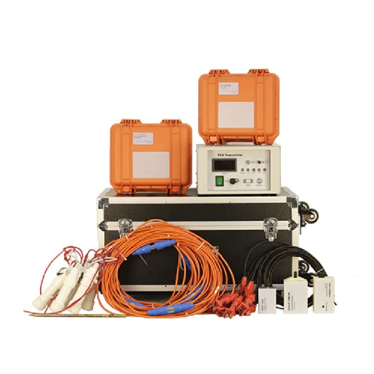
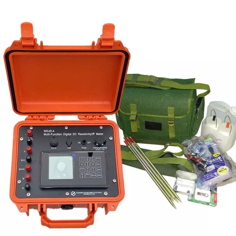
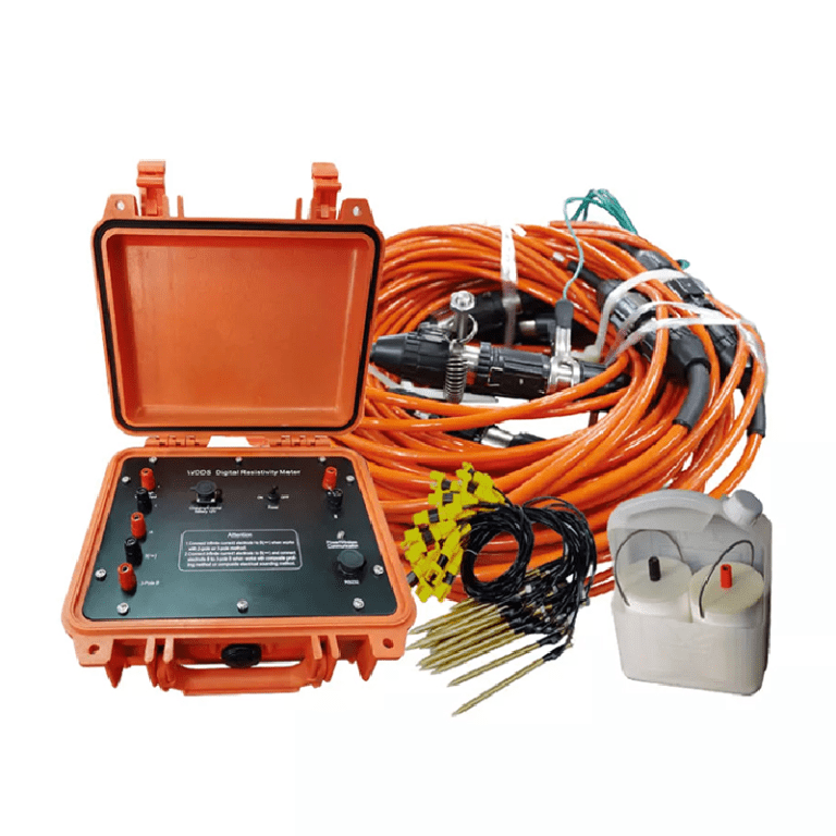
Instruments used
The WGMD-4 high-density electrical method system was used as the measuring instrument. The system uses the WDJD-4 multi-function digital DC induced polarization instrument as the measurement and control host, and is equipped with a WDZJ-4 multi-channel electrode converter to form a high-density resistivity measurement system, which can perform high-density electrical method measurements. The system has a large storage capacity, accurate and fast measurement, stable performance, and a high degree of digitization. It is currently one of the most advanced electrical instruments in China.
Survey line layout and parameter selection The width of each building foundation pit is about 17m, and the length varies from 40 to 108m. Each building is east-west.
3.3.1 Survey line layout
Three east-west sections are laid out in the foundation pit of each building using survey ropes, numbered 1, 2, and 3 from south to north. Sections 1 and 3 are 2m away from the south and north sides of the foundation pit respectively, and section 2 is located in the middle of the foundation pit. The line spacing is maintained between 6.5 and 7.0m. Later, due to the unsatisfactory geological effect of the ground penetrating radar and the needs of the project, two profile lines were added in each foundation pit, that is, one profile was added between the original three profiles. A total of 4.531 km of high-density electrical profiles were measured in 19 foundation pits.
3.3.2 Device and parameter selection
The selection of the device is based on the principles of effective method, simple operation, small terrain impact, small number of personnel, and economic and fast operation [1,5]. According to the field experiments and construction conditions, Wenner and tri-pole devices were selected. Wenner devices were used in foundation pits with small excavation depths, and tri-pole devices were used in foundation pits with large excavation depths (mostly 2 to 4 meters deep). In order to measure the edge of the foundation pit as much as possible and truly reflect the shape of the cavity, the MN2B rolling tri-pole device was used after experimental comparison; the electrode spacing and arrangement length were selected according to the length of the foundation pit, the detection depth and the site conditions. The working electrode spacing was 1.0 to 2.0 m, and the infinite pole vertical measurement line of the tri-pole device was arranged and greater than 10BO.
4 Data interpretation and inference
Analysis of abnormal underground cavity morphology
According to the high-density electrical inversion cross-section diagram of the working area, there are mainly two types of underground cavity anomalies:
1) High-resistance semi-closed circle with upward opening: This type of morphology will appear in shallowly buried cavities (cavity top is about 0.5-1.5m below the foundation pit surface, cavity bottom is less than or equal to 3m below the foundation pit surface, and width is about 1-1.5m). Since the cavity is generally buried 3-10m deep before excavation, and the foundation pit has been excavated to a depth of 2-4m, some cavities are shallower than the foundation pit surface, and the cavities are above the groundwater level. The cavities are not filled with water and are intact. When the underground power supply is measured, the cavities have a strong repulsive effect on the current line in the shallow part, so the resistivity contour lines on the geoelectric cross-section diagram are dense, high-resistance semi-closed circles with upward openings.
2) High-resistance closed loop: This form will appear in deep and large-spaced cavities (cavity top is about 1.5-3.0m below the foundation pit surface, cavity bottom is 3-6m below the foundation pit surface, and length and width are generally 3-7m). The cavity is relatively deep from the foundation pit surface, has a large spatial range and is above the groundwater level. The cavity is not filled with water and is well preserved. When the power supply is measured underground, the current line produces a strong repulsive effect at the cavity position, so the resistivity contour line on the geoelectric section diagram is reflected as a closed high-resistance circle.
Typical profile interpretation example
4.2.1 Section 3 of Building 14
Figure 1 is the apparent resistivity cross-section diagram of the high-density electrical method inversion. The foundation pit is deep, and the MN2B rolling device is used to measure the edge as much as possible. It can be seen from the figure that the contour lines have a high-resistance, dense semi-closed circle with an upward opening in the range of 3 to 12m on the plane and 1.5 to 3.5m in depth. After analysis, it is speculated that the anomaly should be caused by the underground air-raid shelter. The specific spatial location is: a long cavity with a length of 3.5 to 11m, a depth of 1.5 to 3.0m, and a width of about 1.5m. After artificial trench excavation, it was confirmed that the cavity extends for a long time between 3.3 and 1018m, with a cave top of 1.3m, a cave bottom of 2.6m, and a width of 1.3m, which is basically consistent with the results of geophysical exploration.
4.2.2 Section 2 of Building 8
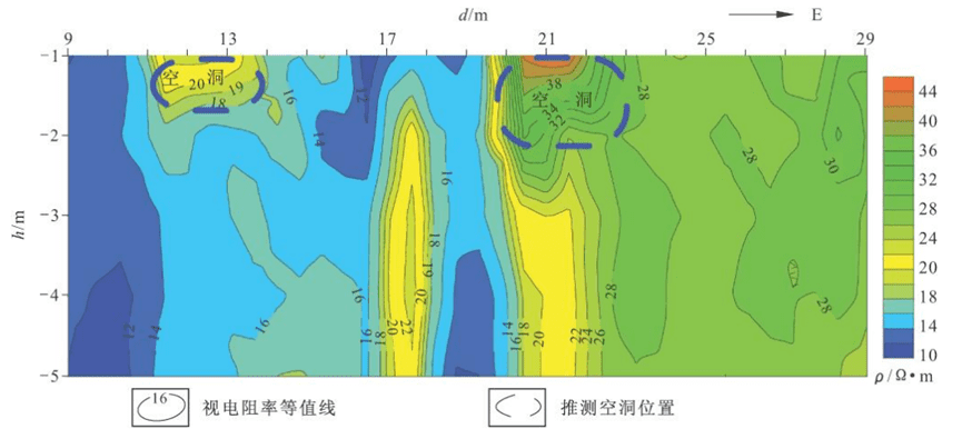
Figure 2 is the high-density electrical inversion apparent resistivity cross-section of the section. The foundation pit is deep, and the MN2B rolling device is selected. It can be seen from the figure that there are two high-resistance semi-closed loop anomalies that open upward. One is between 11 and 14 meters and the depth is within the range of 1.0 to 1.8 meters, and the other is between 20 and 22.3 meters and the depth is within the range of 1.0 to 2.1 meters. After analysis, it is speculated that the two anomalies are caused by underground cavities. Later, the artificial exploration trench excavation confirmed the existence of two cavities, and the spatial morphology was consistent with the results of geophysical exploration.


4.2.3 Section 3 of Building 16
Figure 3 is the apparent resistivity cross-section diagram of the section inverted by high-density electrical method, using the Wenner device. It can be seen from the figure that there are two high-resistance closed circles that are very close to each other, and the outer periphery is included in another closed circle. High-resistance closed circle anomalies are formed between 45-53m and 54-63m, with depths of 2.5-7.0m and 3.3-8.1m respectively. After analysis, it is speculated that the anomaly should be caused by two large underground air-raid shelters that are close to each other. According to the abnormal shape of the high-resistance closed circle, its spatial position is speculated as follows: ① The length is between 45-52m, the depth is 3.2-5.3m, and the width is about 4.0m (predicted based on whether there are anomalies in the adjacent sections); ② The length is between 54-61m, the depth is 3.2-516m, and the width is about 4.0m (predicted based on whether there are anomalies in the adjacent sections). After excavation by an excavator, it was confirmed that there were two large cavities 1.6m apart, and the spatial position was basically consistent with the results of geophysical exploration.
5 Conclusion
1) A total of 133 abnormal locations were found in the excavation pits of 19 high-rise residential buildings in this project. After comprehensive analysis, 43 of them were speculated to be underground cavities. After excavation, 38 actual cavities were verified, with an accuracy rate of 88.37%. The other 5 locations were local gravel layers. Their abnormal characteristics on the geoelectric section were similar to those of cavities and were difficult to distinguish. This also reflects the principle of this interpretation. In order to ensure safety, it is better to speculate several more cavities in advance than to miss a real cavity.
2) The high-density electrical method used in this project to detect underground cavities has a good geological effect, which fully reflects the advantages of this method, which is rich in geoelectric information, high detection accuracy, fast speed and low cost. It is a preferred new method worthy of widespread use in similar projects.
3) When underground cavities and gravel layers coexist in the Quaternary strata, it is necessary to distinguish them by comprehensively analyzing the distribution characteristics of high-resistance anomalies on adjacent sections. Gravel layers or ancient river channels generally have certain regularities such as continuity and a large distribution range, while most underground cavities are relatively independent.
4) When there are uneven high-resistance geological bodies on the surface, false high-resistance anomalies will occur on the high-density electrical geoelectric section. This situation must be handled well. First, dig a pit and fill it with soil at the electrode position before measurement and pour an appropriate amount of salt water; second, if the uneven high-resistance geological body cannot be handled, its specific location must be recorded and excluded during data interpretation. 5) The selection of high-density electrical equipment should be flexibly determined based on experimental results and construction conditions, with the purpose of maximizing the reflection of the abnormal morphology of underground cavities and solving geological problems.
Further reading | Technical solutions related to this article
In the field of resource exploration and engineering testing, accurate data is the key to success. As an innovator of resource and environmental instruments, Geotech has always taken high-precision electrical exploration technology as its core to provide reliable solutions for global users.
If you want to learn more about how the [Electrical Exploration System (ERT)] can help mineral exploration and geological research, please click on the electrical instrument product page to explore details, or visit Geotech’s official website to view the full range of exploration equipment (covering more than ten categories of products such as magnetometers, seismic nodes, and geological radars). Our technical team is on call at any time to customize scientific solutions for your project – making unknown strata a controllable data map.
FAQ
What is the main difference between a single tap and a double tap?
What is the principle of high-density electrical prospecting?
What are the advantages of high-density electrical method?
In what fields is the high-density electrical method generally used?
What are the application characteristics of high-density electrical method?