Welcome to Geotech!



Step-Frequency Ground Penetrating Radar丨GEO-GPR-RCS UWB mm-Resolution GPR




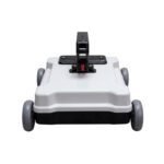
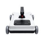

PRODUCT PARAMETERS
Description
 Abstract
The GEO-RCS is an ultra-wideband step-frequency geological radar that scans continuously across 0.5–4 GHz. Unlike fixed-frequency GPR, it balances resolution and penetration depth by adjusting frequency steps, and fuses multi-band data to achieve millimeter-level detection accuracy.
It features an all-in-one design with integrated host and antenna, weighing only 2.1 kg for effortless handheld operation. Its high dynamic range and flexible bandwidth make it a versatile tool for fine-structure detection in transportation, structural engineering, archaeology and cold-region geophysics.
Technical Highlights
- 0.5–4 GHz ultra-wideband stepped scanning. Adjustable frequency steps and midband width let operators tune the system for either fine near-surface resolution or deeper penetration, matching the survey target instead of forcing a fixed-frequency compromise.
- Multi-band fused imaging with mm-level accuracy. Synthesized wideband signals enhance imaging clarity and vertical resolution, delivering millimeter-level layer discrimination for thin pavement structures and delicate subsurface features.
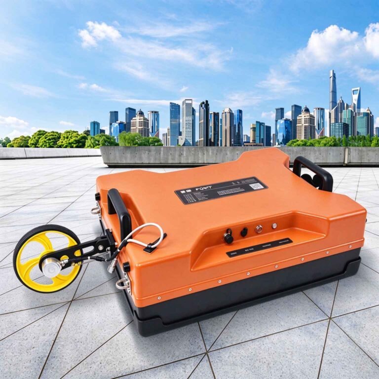
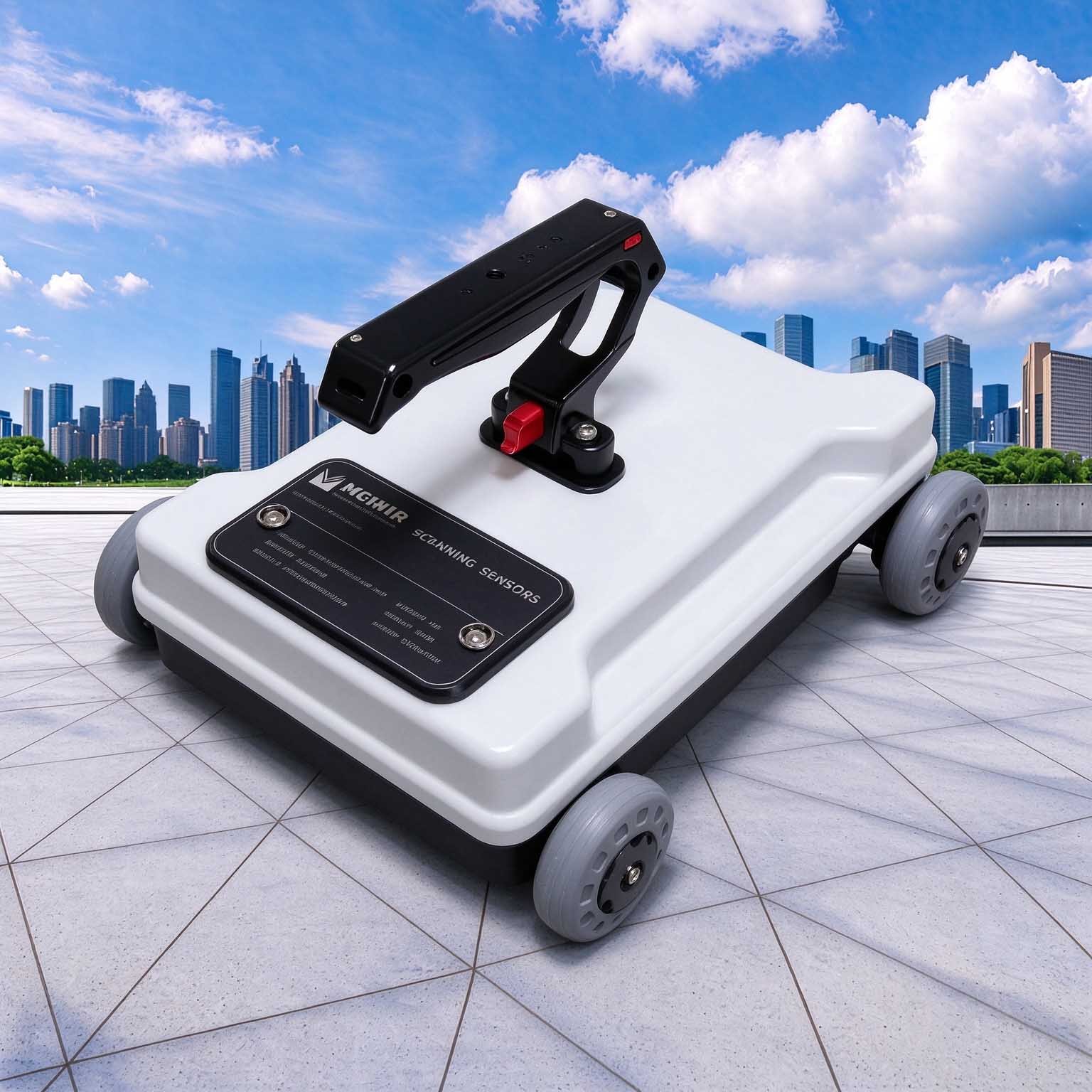
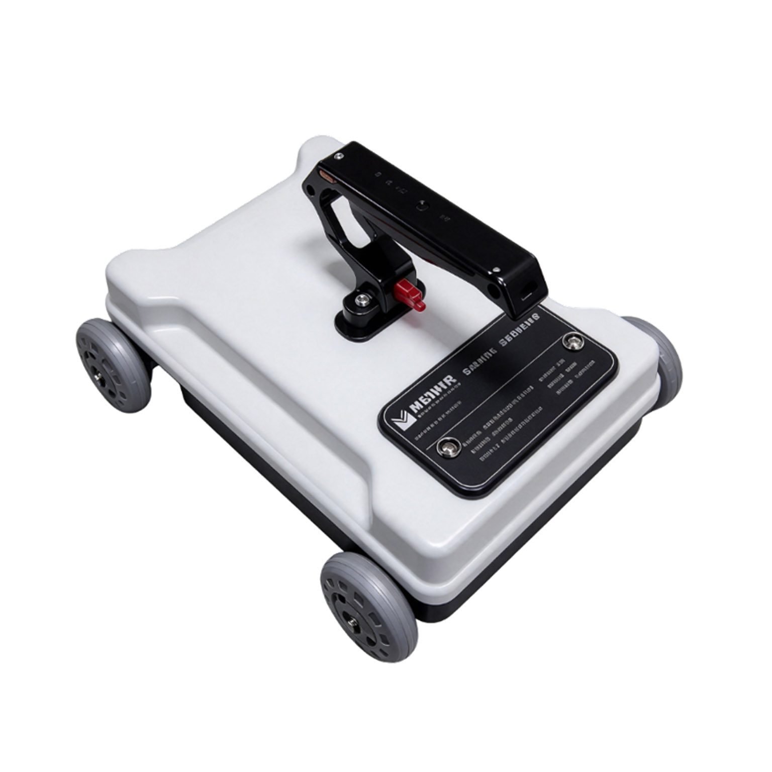
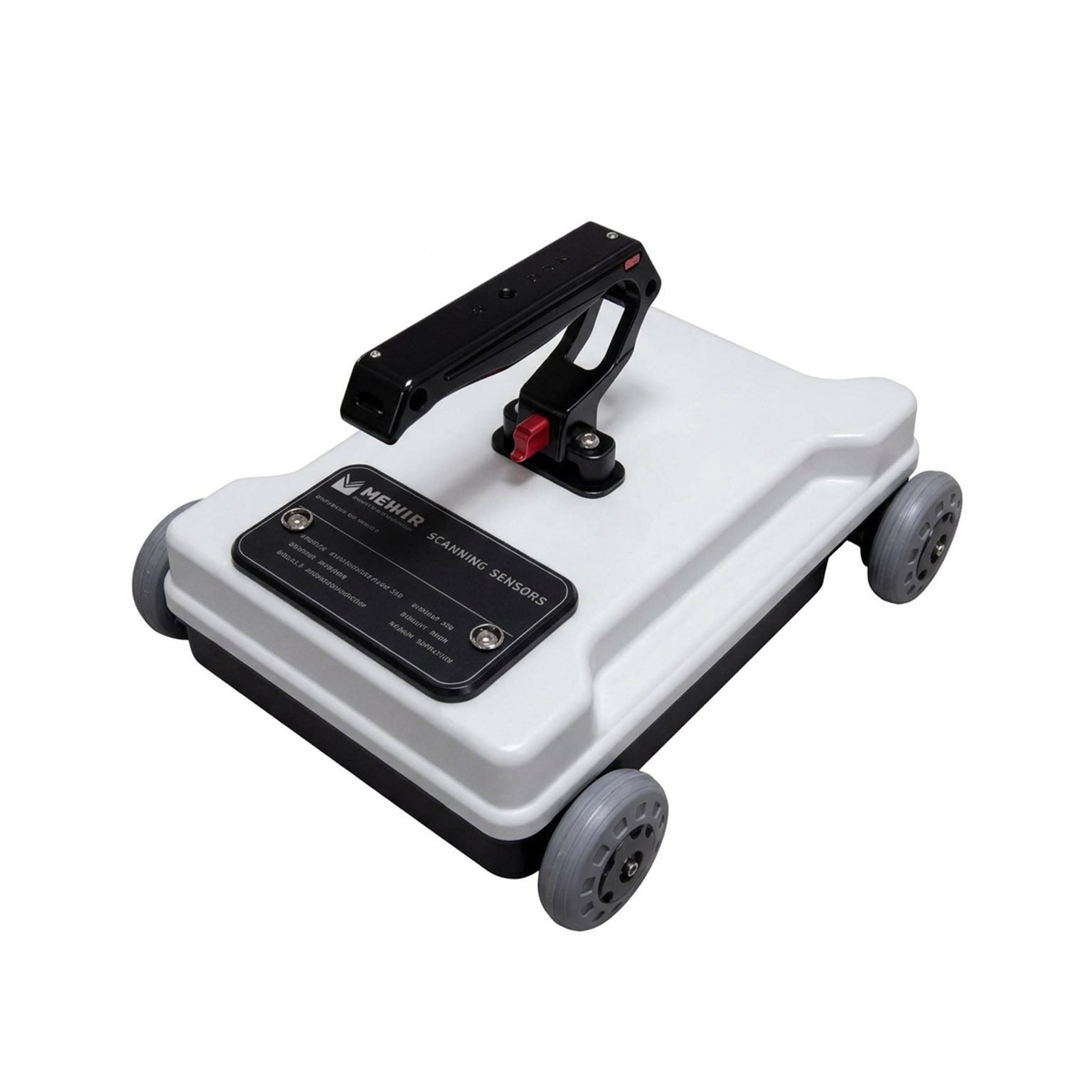
- All-in-one ultra-compact design. Host and antenna integrated in a single 290 × 240 × 155 mm unit weighing only 2.1 kg. Low power consumption and lightweight form factor support all-day handheld surveys without heavy rigging.
- High dynamic range for reliable weak-signal detection. 140 dB system dynamic range and sensitivity better than −120 dB ensure clean data in challenging conditions, with 25 to 4096 selectable scan points to match survey speed and precision requirements.
Features
- Step-frequency ultra-wideband scanning, 0.5–4 GHz frequency range
- Integrated host and antenna design — compact, lightweight, low power
- Adjustable frequency steps and midband width for resolution/depth balance
- Multi-band signal fusion for enhanced imaging quality and mm-level accuracy
- 140 dB system dynamic range, sensitivity better than −120 dB
- 25 to 4096 selectable scan points
- Point-by-point, distance-triggered and continuous acquisition modes
- Pseudo-colour, stacked-waveform and grayscale display options
- ≥8 h continuous operation on internal battery
- −30 °C to +70 °C operating range for extreme field environments
- Compatible with wireless tablet control unit for real-time viewing
Deployment Guidance
| Deployment Mode | What it is best at | Note on capability |
| Handheld | Spot checks, structural verification, confined-space surveys | Full resolution; single-operator workflow for targeted inspection |
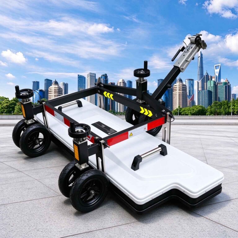
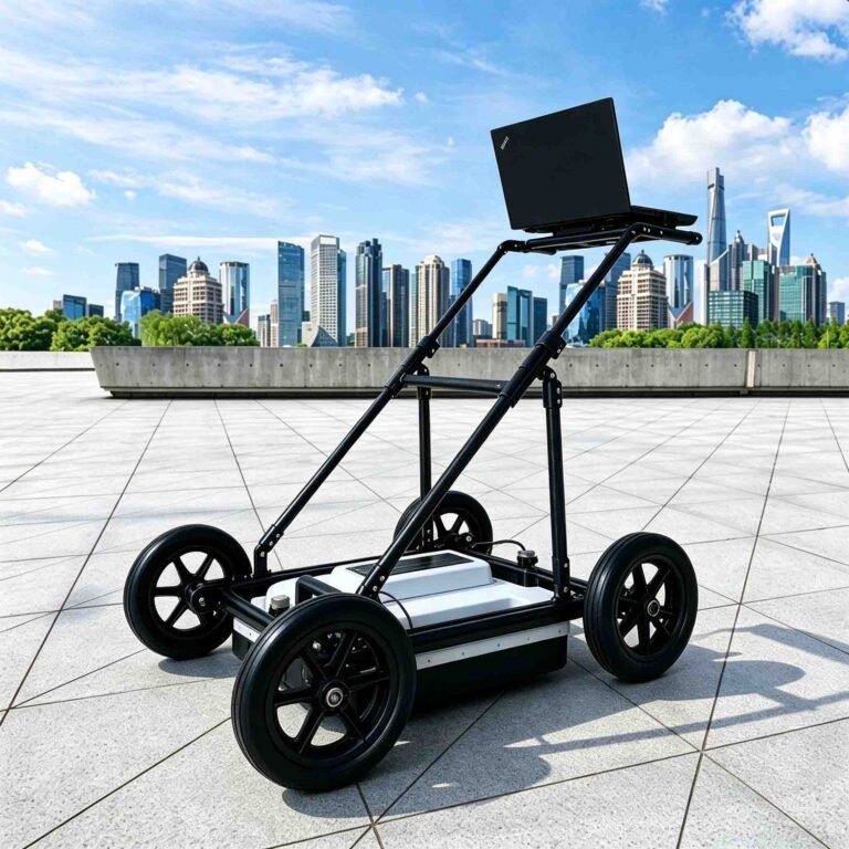
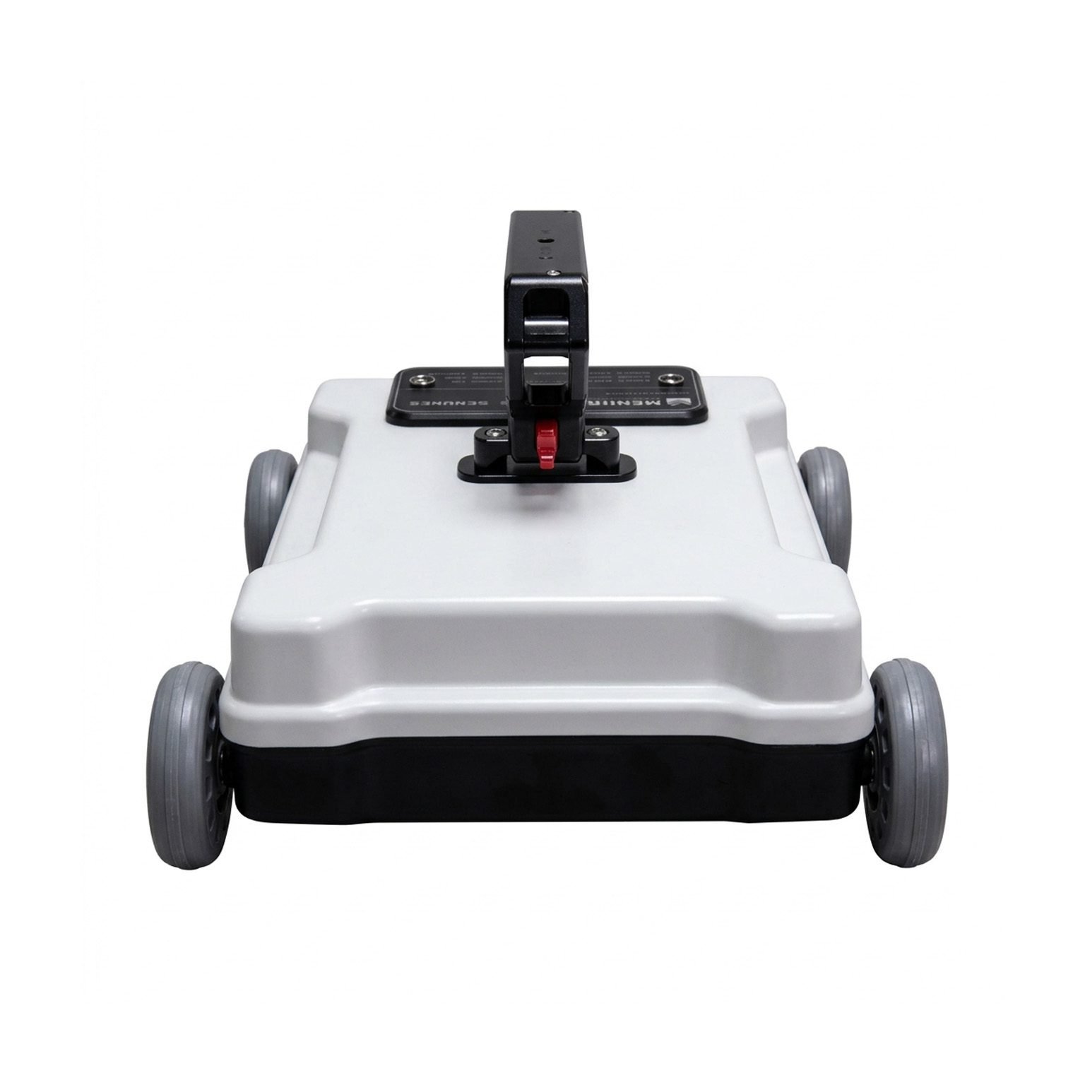
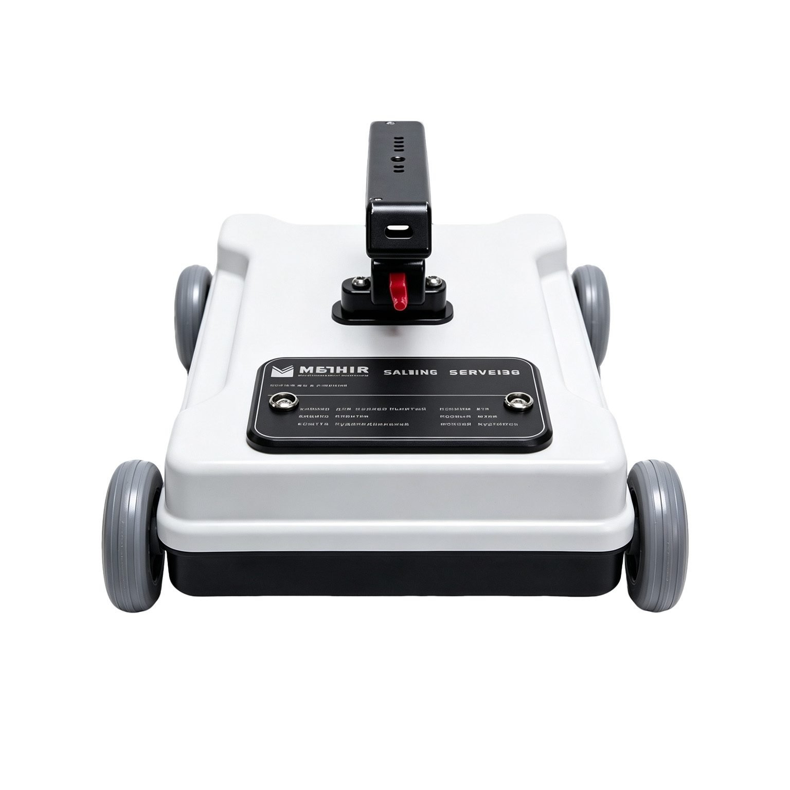
| Wheeled trolley | Continuous pavement and runway layer mapping | Constant-speed profiling for lane-scale engineering quality control |
| Robotic / UGV platform | Hazardous or hard-to-reach areas, automated routine surveys | Mission endurance set by the platform, not the instrument |
The ≥8 h continuous-operation figure applies to standalone handheld use. Trolley and robotic mounting kits, data export utilities and calibration standards are supplied with each system configuration.
Why Step-Frequency GPR, and Where It Stops
Step-frequency radar trades vertical resolution against penetration depth via frequency tuning. Higher frequency bands deliver finer detail but shallower reach; lower bands extend depth at the cost of resolution. Multi-band fusion combines the strengths of multiple bands for balanced performance.
| Target Material / Scenario | Typical Vertical Resolution | Effective Depth Range | Suitability |
| Thin asphalt overlay, surface defects | ~1 mm | 0 – 0.1 m | Excellent |
| Pavement layer structure, concrete slabs | 3 – 5 mm | 0.1 – 0.5 m | Excellent |
| Reinforced concrete structural members | 5 – 10 mm | 0.5 – 1.0 m | Good |
| Dry sand, shallow soil stratigraphy | 10 – 20 mm | 1.0 – 2.0 m | Moderate |
| Moist clay, saturated soil | 30 – 50 mm | 0.3 – 0.8 m | Limited |
| Highly conductive wet soil, standing water | N/A | < 0.2 m | Marginal |
Read this as the design rule: step-frequency GPR excels at high-resolution shallow-to-medium depth surveys. Where the target lies deeper than 2 m in conductive ground, use a low-frequency unshielded GPR system instead — note that water content, rebar density and conductive aggregates will reduce effective depth as described.
Applications

| Application | What the BD-RCS delivers | Reference depth |
| Transportation pavement layer inspection | Continuous mm-accurate mapping of asphalt overlay, base course and interlayer bonding defects | 0.05 – 0.6 m |
| Structural concrete inspection | Rebar location, delamination detection and thickness measurement of bridge decks, tunnels and building elements | 0.05 – 1.0 m |
| Archaeology and heritage survey | Non-destructive detection of shallow underground relics, ancient foundations and burial structures with high resolution | 0.1 – 1.5 m |
| Permafrost and glacier survey | Fine stratigraphy of active layers, melt zones and near-surface ice structures in cold regions | 0.2 – 2.0 m |
| Pavement quality acceptance | Non-destructive layer thickness verification for road construction quality control | 0.02 – 0.5 m |
Reference depth bands are given for planning. Because step-frequency performance depends most strongly on material permittivity and conductivity, depth is confirmed against your site conditions before a proposal is issued — full frequency-versus-depth documentation available on request.
Specifications
| Parameter | Specification |
| Radar type | Step-frequency ultra-wideband geological radar |
| Scan frequency range | 0.5 – 4 GHz |
| Midband width | Adjustable from 10 Hz to 1 MHz |
| System sensitivity | Better than −120 dB |
| System dynamic range | Better than 140 dB |
| Scan point count | 25 – 4096, selectable |
| Antenna | 1.5 GHz antenna array, integrated design |
| Total system weight | 2.1 kg |
| Outline dimensions | 290 × 240 × 155 mm |
| Continuous operating time | ≥8 h (built-in battery) |
| Acquisition modes | Point-by-point, distance-triggered, continuous |
| Display modes | Pseudo-colour, stacked waveform, grayscale |
| Real-time processing | Onboard imaging with instant profile output |
| Operating temperature | −30 °C to +70 °C |
Survey speed, spatial resolution, depth performance by material and full data export specifications are published in the technical datasheet and issued with each configuration proposal.
FAQ
In gravity exploration (SI), what is the unit of gravity? How to convert gravity units between SI and CGS?
① In SI, it is m·s-2, and one percent of it is the international unit abbreviation g.u.;
② Conversion between SI and CGS: 1g.u.=10-1 mGal
What are gravitational field and gravitational potential?
Gravitational field: The space around the earth with gravity is called the gravitational field.
Gravitational potential: The gravitational potential W in the gravitational field is equal to the work done by a particle of unit mass moving from infinity to that point.
What is the normal gravity field of the earth? What are the rules for the change of the normal gravity field with latitude and altitude?
① The normal gravity field of the earth: Assuming that the earth is a rotating ellipsoid (reference plane), the surface is glossy, the internal density is uniform, or it is distributed in concentric layers, the density of each layer is uniform, and the deviation of the shape of the ellipsoid from the geoid is very small, then the gravity field generated by the earth is the normal gravity field.
② The normal gravity value is only related to the latitude, the smallest at the equator and the largest at the poles, with a difference of about 50,000 g.u.; the rate of change of the normal gravity value with latitude is the largest at 45° latitude, and zero at the equator and the poles; the normal gravity value decreases with increasing altitude, and its rate of change is -3.086 g.u.. The main feature of the long-term change is the "westward drift" of the geomagnetic elements, both the dipole field and the non-dipole field drift westward, and have a global nature.
What is the relationship between gravitational field strength and gravitational acceleration?
The gravitational field strength is equal to the gravitational acceleration in both numerical and dimensional terms, and the two are in the same direction. In gravity exploration, all references to gravity refer to gravitational acceleration. The gravitational field strength at a point in space is equal to the gravitational acceleration at that point.
What is gravity exploration?
Gravity exploration is an exploration method that is based on the density difference of rocks and ores. Since density difference will cause local changes in the normal gravity field of the earth (i.e. gravity anomaly), it is used to solve geological problems by observing and studying gravity anomalies.