Welcome to Geotech!



Air‑Coupled Non‑Contact Horn‑Antenna Ground Penetrating Radar丨GEO-GPR-A
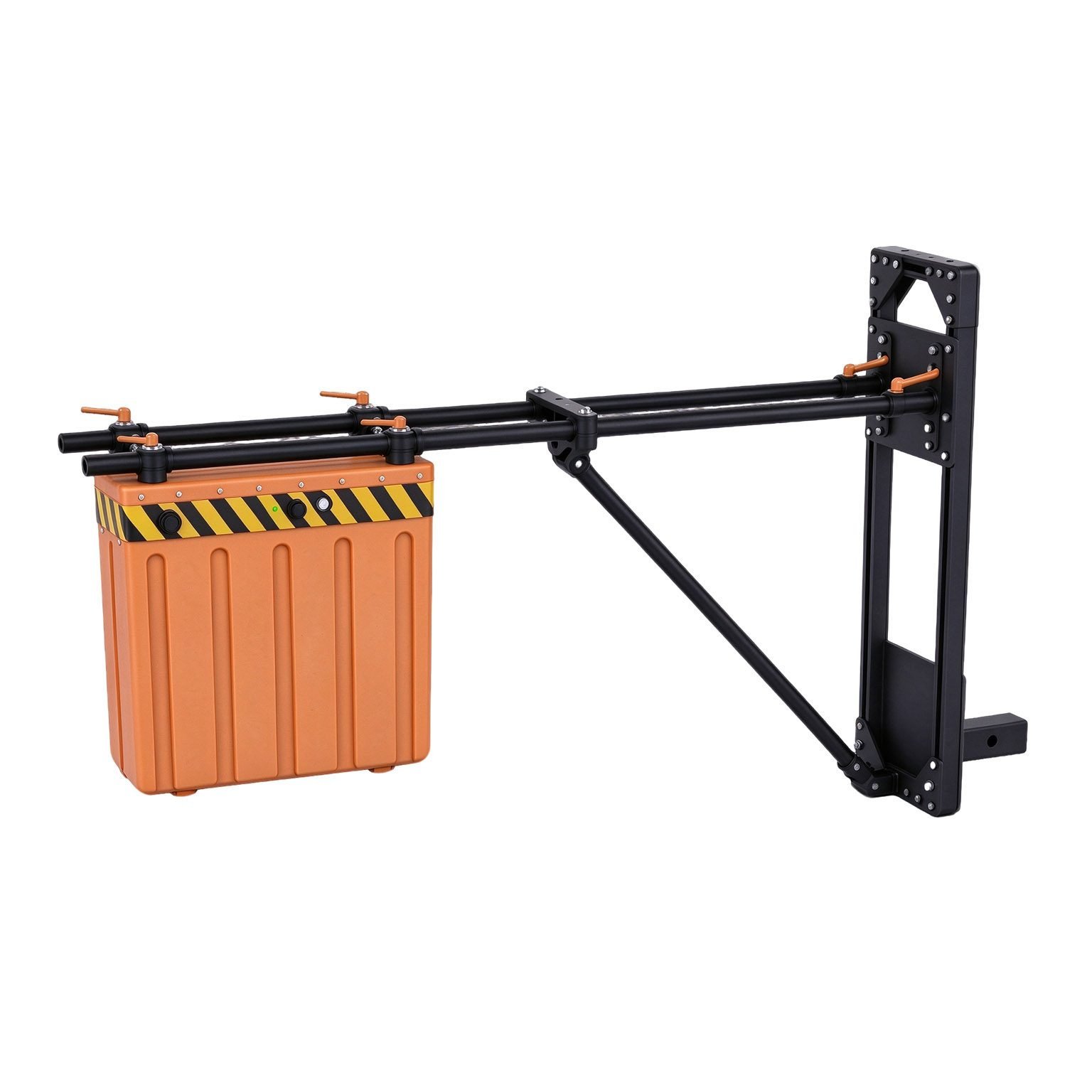



PRODUCT PARAMETERS
Description
 Abstract
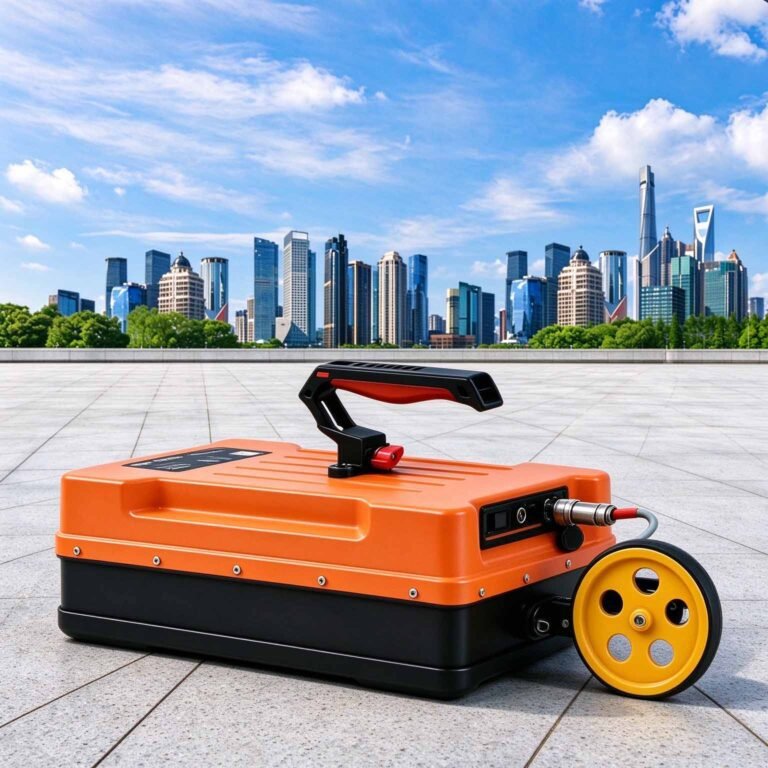
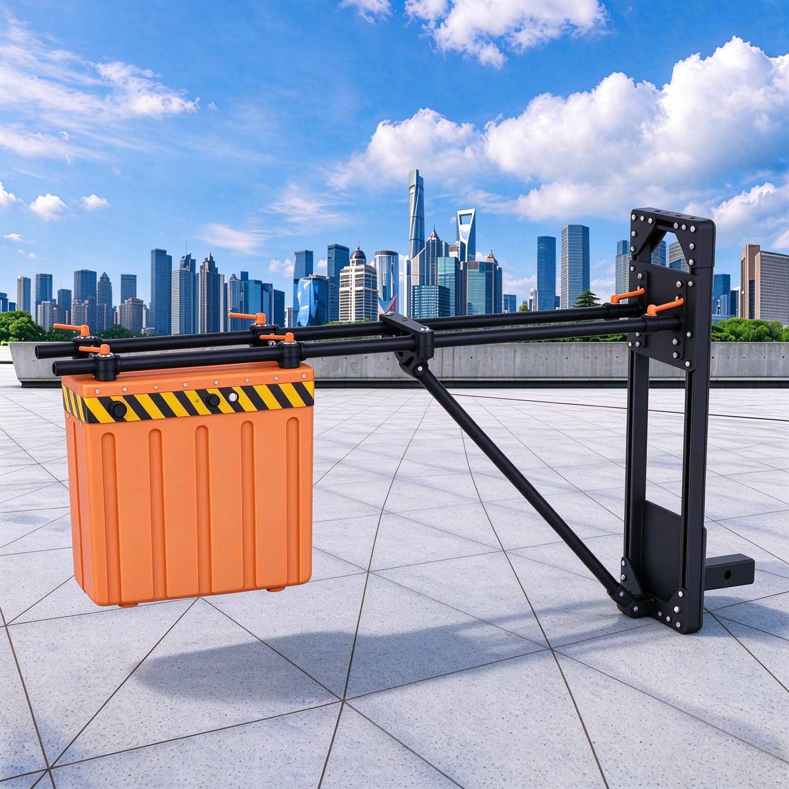
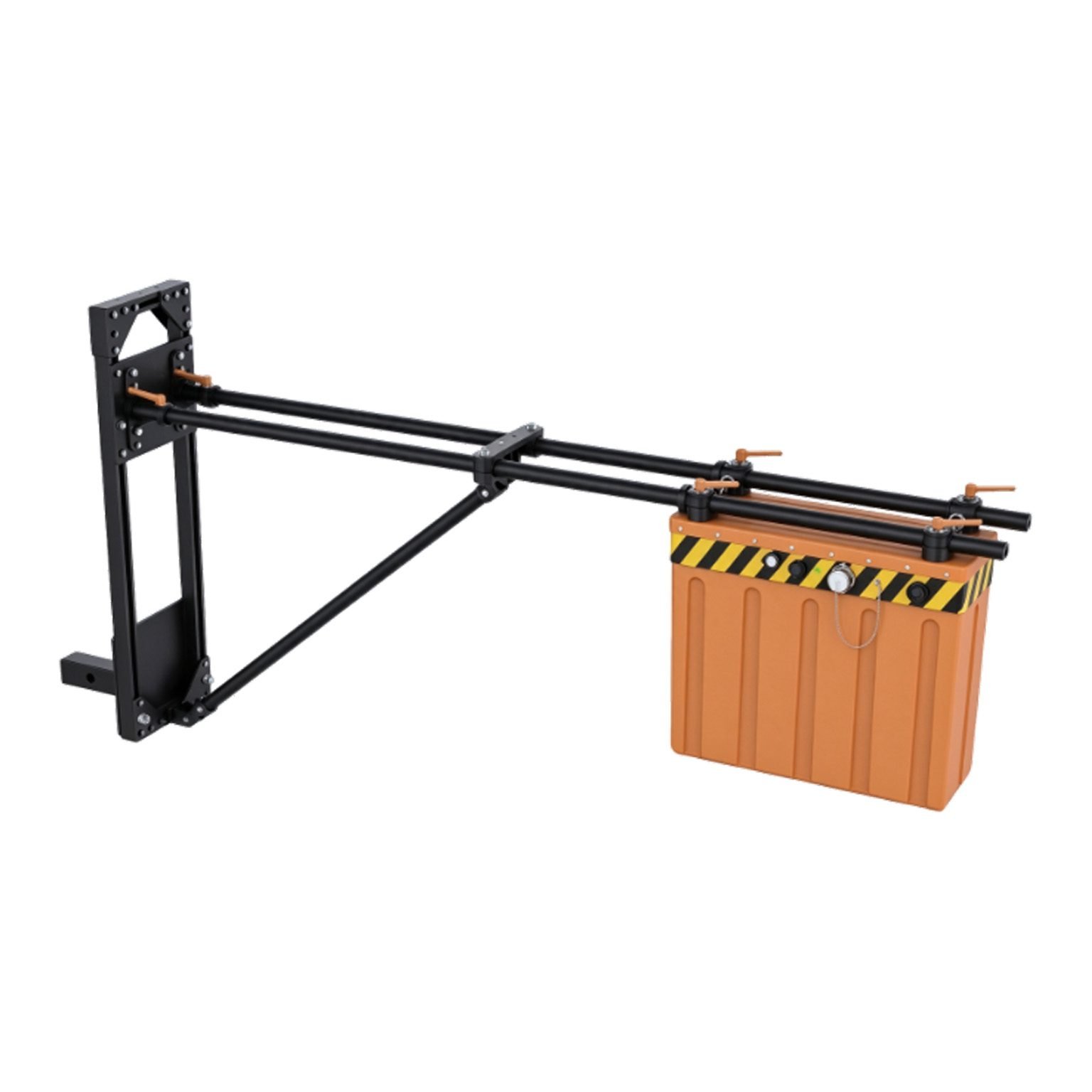
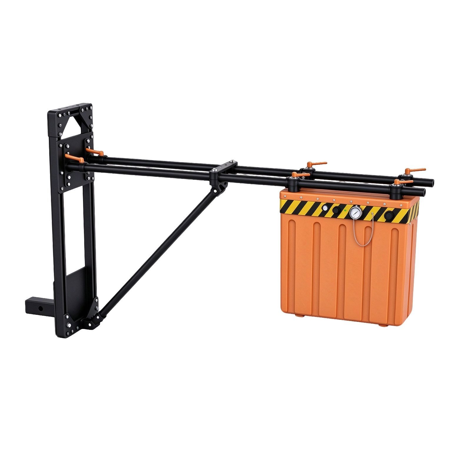
The GEO-GPR-A is an air-coupled ground penetrating radar — a non-contact GPR whose horn antennas survey from above the surface with no coupling to the ground at all. Because nothing touches the pavement, the same antenna can run at highway speed over asphalt that would abrade a ground-coupled unit, cross a runway without foreign-object-debris risk, and read snow, ice or a frozen surface in winter conditions where contact coupling fails.
It weighs under 4 kg and mounts on a vehicle rear frame, an inspection truck, a multirotor drone, a helicopter skid or a portable hand frame. Two horn options — 1 GHz and 2 GHz centre frequency — set the depth-versus-resolution choice: 1 GHz for pavement layers and snow/firn structure, 2 GHz where the answer must come from the top few centimetres.
Technical Highlights
- No contact, no coupling loss to the operator. There is no gel, no skid shoe, no wheel to keep seated on the surface, and no dependence on surface conductivity. Roughly 79 to 90 per cent of the transmitted energy crosses the air–surface interface on the round trip in asphalt, ice and snow, which is what makes non-contact survey practical in those materials.
- Centimetre-scale layer resolution. A quarter-wavelength resolution cell of about 3.1 cm at 1 GHz in concrete or asphalt, and 1.5 cm at 2 GHz, turns pavement and runway layer thickness from an estimate into a directly measurable value.
- Under 4 kg on any platform. Light enough to fly. Vehicle, drone, helicopter, handheld and small-platform mounting all run the same antenna and the same real-time imaging software, so a network-level programme and a spot survey share one data model.
- Real-time profile on the move. Onboard processing returns the section as it is acquired, so lane closures, coring positions and repair decisions are made on site rather than after the crew leaves.
Features
- Non-contact horn antenna, 1 GHz or 2 GHz centre frequency
- Total system mass under 4 kg — suitable for UAV payload limits
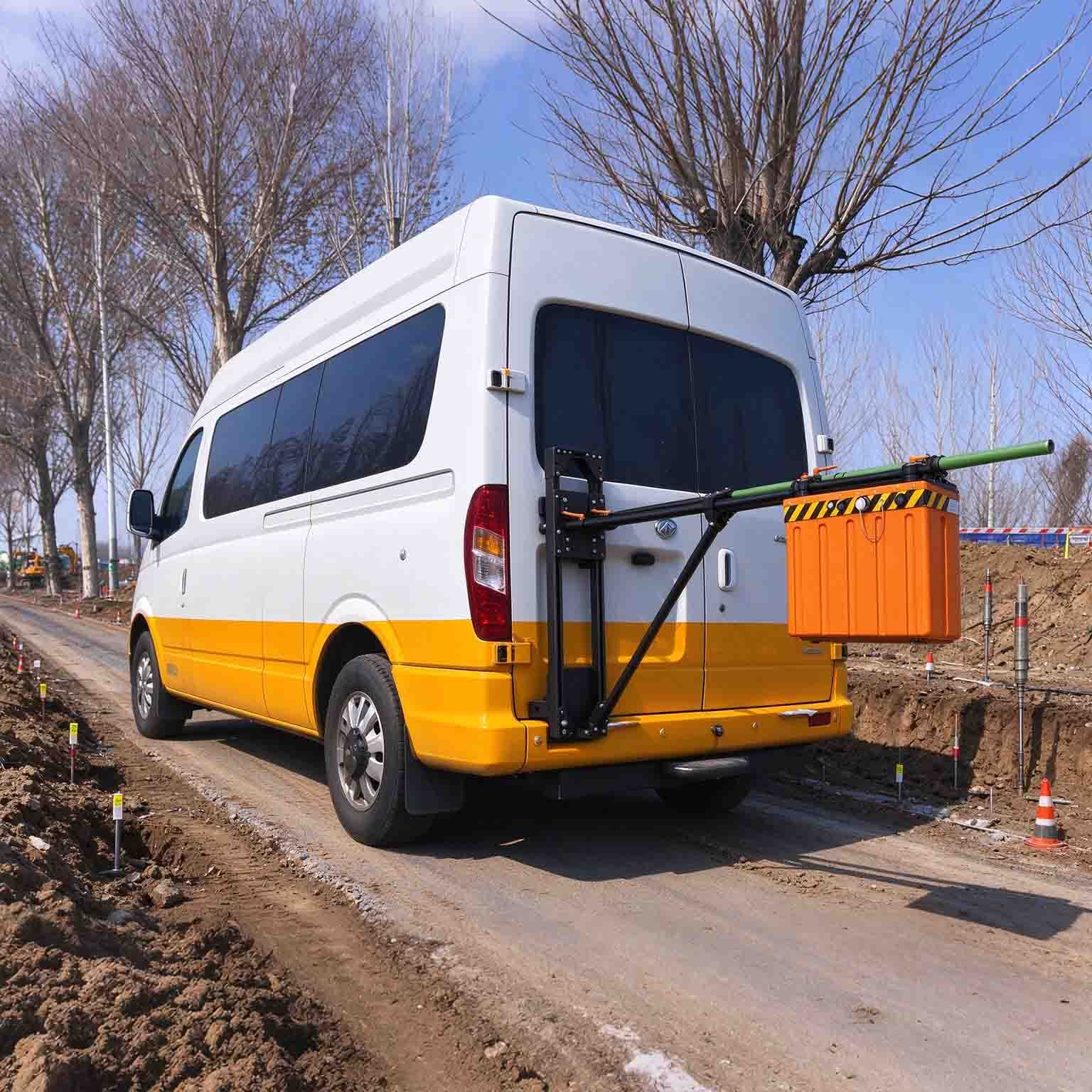
- Vehicle-rear mounting kit for continuous lane survey
- Drone, helicopter, handheld and small-platform configurations
- Real-time onboard imaging with instant profile display
- Point-by-point, distance-triggered and continuous acquisition modes
- Pseudo-colour, stacked-waveform and grayscale display
- ≥8 h continuous operation on internal battery in ground and vehicle configurations
- −30 °C to +70 °C operating range for winter and polar work
- Wireless link of at least 50 m to the control unit
Platform Guidance
| Platform | What it is best at | Note on capability |
| Vehicle / inspection van | Lane-continuous pavement and runway layer survey | Speed and swath are set by the trigger interval you specify |
| Multirotor drone | Slopes, bridge undersides, restricted airspace, glacier reach | Flight endurance, not the instrument, sets the line length |
| Helicopter | Long linear corridors in remote terrain | Standoff stability governs thin-layer accuracy |
| Handheld / portable | Spot checks, test pits, structural verification | Full resolution without a rig |
The ≥8 h continuous-operation figure applies to ground and vehicle use. On an aircraft, mission length is set by the platform’s endurance, and payload, mount and power requirements are issued with the flight configuration sheet.
Why Air-Coupled, and Where It Stops
Interface transmission controls what non-contact GPR can reach. Power reflection at normal incidence is R = ((1 − √εr)/(1 + √εr))², so the round trip through the surface returns the following usable energy:
| Surface | Single-pass transmission | Round trip | Suitability |
| Dry snow | 94.9% | 90.1% | Excellent |
| Ice | 92.2% | 85.0% | Excellent |
| Asphalt, dry soil | 88.9% | 79.0% | Good, shallow |
| Moist concrete and asphalt | 82.3% | 67.8% | Good, shallower |
| Wet concrete, sound limestone | 75.0% | 56.2% | Limited |
| Very wet soil | 52.2% | 27.3% | Marginal |
| Fresh water | 36.0% | 13.0% | Not applicable |
Read this as the design rule: air-coupled GPR trades depth for speed and for surfaces that must not be touched. Where the target sits below wet, conductive ground, use a shielded ground-coupled GEO-GPR antenna instead — and note that dense vegetation, water films and saturated surfaces attenuate the return in exactly the way the lower rows describe.
Applications

| Application | What the GEO-GPR-A delivers | Reference depth |
| Highway pavement layer thickness | Continuous layer boundaries at lane scale without coupling to the surface | 0.1–0.6 m at 1 GHz |
| Airport runway and apron survey | Layer and repair-zone mapping at driving speed, with no debris risk from dragging gear | 0.1–0.6 m |
| Bridge deck and asphalt overlay check | Overlay thickness and delamination detection over live decks | 0.05–0.4 m |
| Snow depth and firn stratigraphy | Snowpack depth and layering, the medium where air coupling loses least energy | several metres |
| Glacier near-surface structure | Shallow internal reflectors, crevasse infill and melt layers | site-dependent |
| Permafrost active-layer mapping | Active-layer thickness and frozen-boundary response in cold, dry ground | 0.3–2 m |
| Frozen and paved ground in winter | Survey where a ground-coupled antenna cannot be seated | 0.1–0.5 m |
Reference depth bands are given for planning. Because air-coupled reach depends on surface moisture and permittivity more than on any other variable, depth is confirmed against your own site data before a proposal is issued — full frequency-versus-depth documentation available on request.
Specifications
| Parameter | Specification |
| Antenna type | Air-coupled horn antenna, non-contact |
| Centre frequency | 1 GHz or 2 GHz |
| Resolution (λ/4) | ≈3.1 cm at 1 GHz, ≈1.5 cm at 2 GHz in concrete/asphalt |
| Contact requirement | None — operates suspended above the surface |
| Total system weight | ≤4 kg |
| Continuous operating time | ≥8 h (ground and vehicle configurations) |
| Wireless data range | ≥50 m |
| Acquisition modes | Point-by-point, distance-triggered, continuous |
| Display modes | Pseudo-colour, stacked waveform, grayscale |
| Real-time processing | Onboard imaging with instant profile output |
| Mounting platforms | Vehicle, drone, helicopter, handheld, small portable frame |
| Operating temperature | −30 °C to +70 °C |
Survey speed, swath width, standoff height, positioning option and full depth performance by material are published in the technical datasheet and issued with each configuration proposal.
FAQ
In gravity exploration (SI), what is the unit of gravity? How to convert gravity units between SI and CGS?
① In SI, it is m·s-2, and one percent of it is the international unit abbreviation g.u.;
② Conversion between SI and CGS: 1g.u.=10-1 mGal
What are gravitational field and gravitational potential?
Gravitational field: The space around the earth with gravity is called the gravitational field.
Gravitational potential: The gravitational potential W in the gravitational field is equal to the work done by a particle of unit mass moving from infinity to that point.
What is the normal gravity field of the earth? What are the rules for the change of the normal gravity field with latitude and altitude?
① The normal gravity field of the earth: Assuming that the earth is a rotating ellipsoid (reference plane), the surface is glossy, the internal density is uniform, or it is distributed in concentric layers, the density of each layer is uniform, and the deviation of the shape of the ellipsoid from the geoid is very small, then the gravity field generated by the earth is the normal gravity field.
② The normal gravity value is only related to the latitude, the smallest at the equator and the largest at the poles, with a difference of about 50,000 g.u.; the rate of change of the normal gravity value with latitude is the largest at 45° latitude, and zero at the equator and the poles; the normal gravity value decreases with increasing altitude, and its rate of change is -3.086 g.u.. The main feature of the long-term change is the "westward drift" of the geomagnetic elements, both the dipole field and the non-dipole field drift westward, and have a global nature.
What is the relationship between gravitational field strength and gravitational acceleration?
The gravitational field strength is equal to the gravitational acceleration in both numerical and dimensional terms, and the two are in the same direction. In gravity exploration, all references to gravity refer to gravitational acceleration. The gravitational field strength at a point in space is equal to the gravitational acceleration at that point.
What is gravity exploration?
Gravity exploration is an exploration method that is based on the density difference of rocks and ores. Since density difference will cause local changes in the normal gravity field of the earth (i.e. gravity anomaly), it is used to solve geological problems by observing and studying gravity anomalies.