Welcome to Geotech!



400 + 900 MHz Dual-Frequency Ground Penetrating Radar丨GEO-GPR-S








PRODUCT PARAMETERS
Description
 Abstract
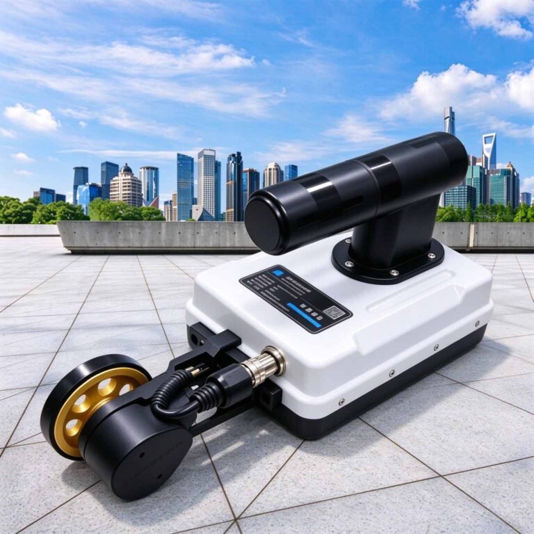
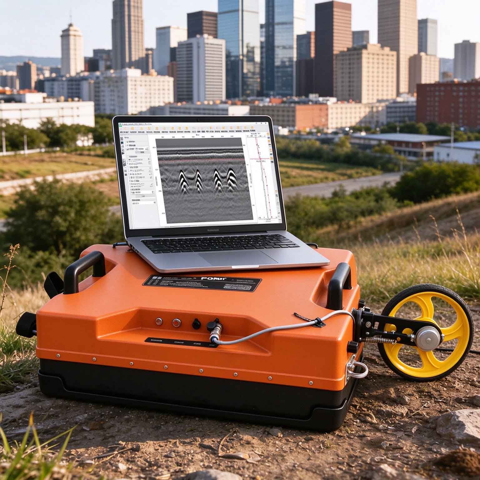
The GEO-GPR-S 400 + 900 MHz dual-frequency ground penetrating radar is built for high-resolution road, lining, deck and void surveys where dense near-surface coverage is essential. The 400 MHz and 900 MHz bands are collected at the same trace positions in a single pass, combining complementary imaging information while the 0.45 m swath width meets a 0.5 m line-spacing requirement in one pass.
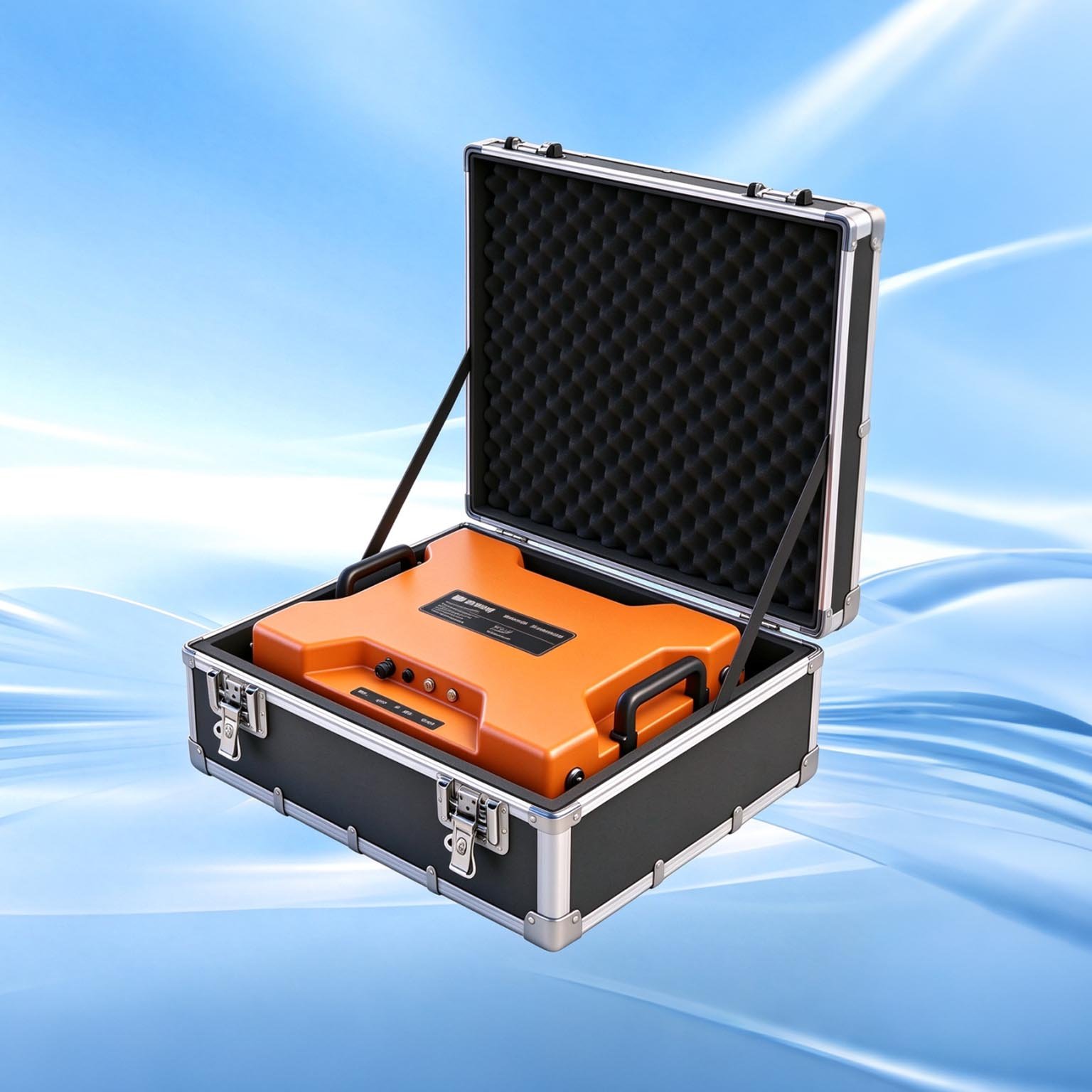
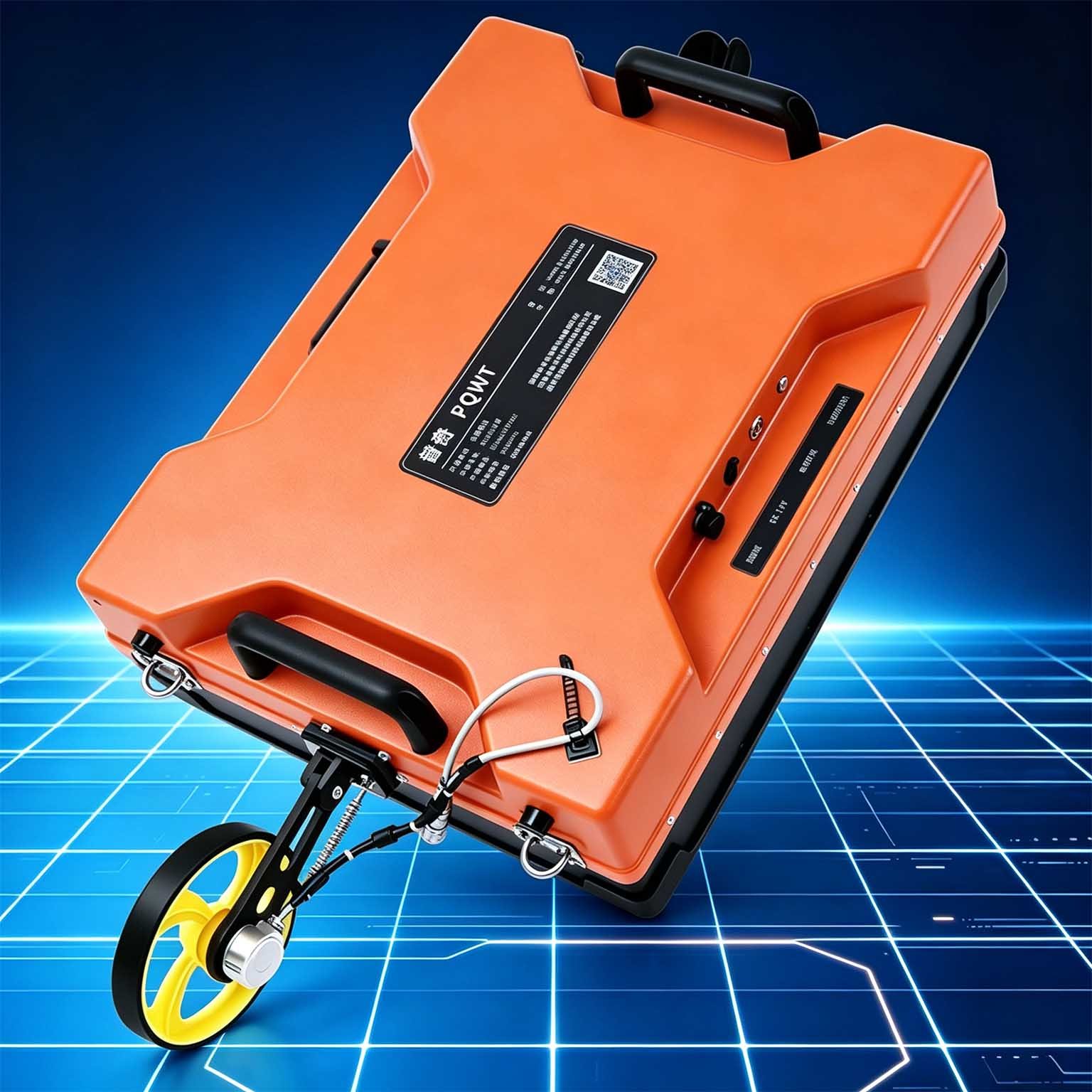
This is the most compact and lightest configuration in the GEO-GPR-S lineup, with a total system mass of 5.85 kg and an envelope of 450 × 310 × 170 mm. Its stated maximum detection depth is 5 m. It is the normal specification for void detection and service location when the survey must meet a 400 MHz line density of 0.5 m in a single pass.
Why Choose the 400 + 900 MHz Dual-Frequency Configuration?
- Municipal road and void-detection codes require 400 MHz line spacing no greater than 0.5 m. With a 0.45 m envelope width, the GEO-GPR-S 400 + 900 MHz satisfies ≤0.5 m code density natively—eliminating extra fill-in passes.
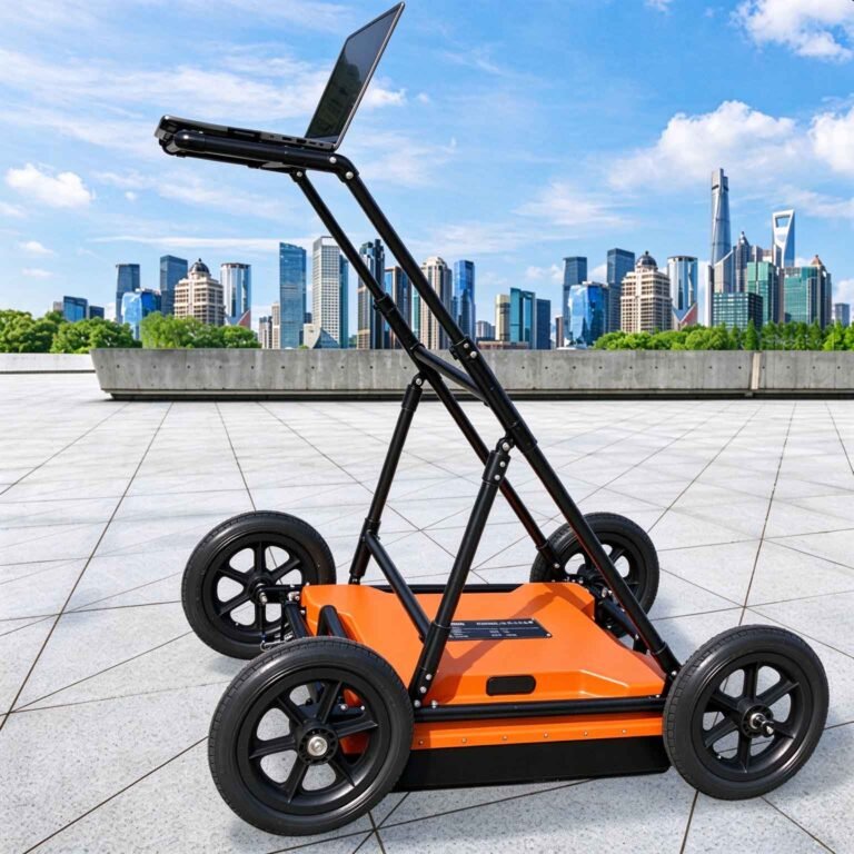
- At only 5.85 kg, a single operator can effortlessly push, carry, or mount the antenna for overhead tunnel crown scanning, bridge deck walking surveys, and tight urban lane inspections.
- On one synchronized trace, the 900 MHz band resolves thin asphalt overlays, concrete delamination, rebar spacing, and lining thickness, while the 400 MHz band images roadbed cavities, subgrade moisture, and rock/grout conditions behind tunnel linings down to 5 m.
Key Features & Benefits
- High-resolution frequency pairing: the 400 MHz and 900 MHz bands provide complementary information for detailed near-surface investigation.
- Single-pass lane coverage: the 0.45 m swath width meets a 0.5 m line-spacing requirement in a single pass, supporting lane-compliant survey layouts where that criterion applies.
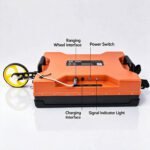
- Compact, lightweight configuration: total system mass is 5.85 kg, with an envelope of 450 × 310 × 170 mm.
- Co-located dual-band data: both bands are acquired at the same trace positions, allowing target detail and surrounding structure to be interpreted together without merging separate survey runs.
- Flexible operation: choose low-band only, high-band only or dual-frequency acquisition to suit the required balance of data detail and survey efficiency.
Field Survey & Line-Spacing Guidance
CODE-COMPLIANT SPECIFICATION FOR ROAD & STRUCTURAL NDT
For municipal road void detection and shallow utility location against strict ≤0.5 m line-spacing standards, the GEO-GPR-S 400 + 900 MHz (0.45 m swath width, 5 m max depth in dry low-loss ground) is the recommended standard specification—achieving full code coverage in a single pass without supplementary lines.
Applications

| Application | How the Dual-Frequency Configuration Helps |
| Road void and cavity detection | Use the dual-band record to investigate voids and their surrounding near-surface structure with the line density required for acceptance work. |
| Municipal road and pavement survey | Resolve shallow layer boundaries and pavement-related features with a compact system designed for dense survey coverage. |
| Tunnel lining inspection | Assess lining thickness and near-surface detail while imaging the ground behind the lining in the same survey. |
| Bridge deck inspection | Combine overlay and delamination detail with the response of the deck substrate in one pass. |
| Pipeline and cable location | Use the higher-frequency response to pinpoint shallow services and interpret their immediate surroundings. |
Configuration & Survey-Line Guidance
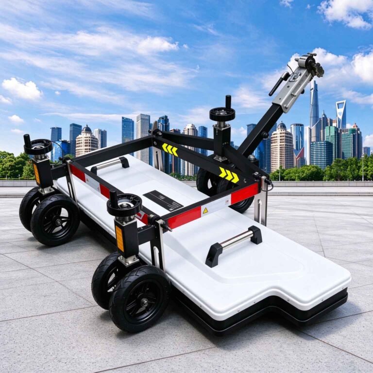
The 400 + 900 MHz antenna has a swath width of 0.45 m and meets a 0.5 m line-spacing requirement in a single pass. For void detection and service location against code line density, this is normally the correct specification. Its stated maximum detection depth is 5 m; where the target depth beyond 5 m governs the survey, select the 100 + 400 MHz configuration and plan the line layout around the required 400 MHz density.
Specifications
| Parameter | Specification |
| Centre frequencies | 400 + 900 MHz |
| Maximum detection depth | 5 m (400 MHz low band) |
| Swath width | 0.45 m |
| Total system mass | 5.85 kg |
| Envelope dimensions | 450 × 310 × 170 mm |
| Acquisition modes | Low band only / high band only / dual-frequency, switchable |
| Scan rate | 350 traces/s |
| A/D conversion | 18 bit |
| Signal-to-noise ratio | Better than 160 dB |
| Total power consumption | ≤16 W |
| Continuous operating time | ≥8 h |
| Wireless data range | ≥50 m |
| Operating voltage | 10–15 V DC |
| Operating temperature | −30 °C to +70 °C |
| Control and setup | One-click parameter setup with automatic acquisition configuration |
| Display | Real-time display of both bands during the survey |
| System design | Integrated host-and-antenna design; compact, wireless and low power |
| Custom frequency combinations | Available on request |
Depth note: Maximum depth is governed by the lower-frequency band and is quoted for dry, low-loss ground. Conductive and saturated conditions can reduce achievable depth materially.
Datasheet note: Time window, trace interval, survey speed, positioning option and ingress protection are published in the full technical datasheet and are available on request.
FAQ
In gravity exploration (SI), what is the unit of gravity? How to convert gravity units between SI and CGS?
① In SI, it is m·s-2, and one percent of it is the international unit abbreviation g.u.;
② Conversion between SI and CGS: 1g.u.=10-1 mGal
What are gravitational field and gravitational potential?
Gravitational field: The space around the earth with gravity is called the gravitational field.
Gravitational potential: The gravitational potential W in the gravitational field is equal to the work done by a particle of unit mass moving from infinity to that point.
What is the normal gravity field of the earth? What are the rules for the change of the normal gravity field with latitude and altitude?
① The normal gravity field of the earth: Assuming that the earth is a rotating ellipsoid (reference plane), the surface is glossy, the internal density is uniform, or it is distributed in concentric layers, the density of each layer is uniform, and the deviation of the shape of the ellipsoid from the geoid is very small, then the gravity field generated by the earth is the normal gravity field.
② The normal gravity value is only related to the latitude, the smallest at the equator and the largest at the poles, with a difference of about 50,000 g.u.; the rate of change of the normal gravity value with latitude is the largest at 45° latitude, and zero at the equator and the poles; the normal gravity value decreases with increasing altitude, and its rate of change is -3.086 g.u.. The main feature of the long-term change is the "westward drift" of the geomagnetic elements, both the dipole field and the non-dipole field drift westward, and have a global nature.
What is the relationship between gravitational field strength and gravitational acceleration?
The gravitational field strength is equal to the gravitational acceleration in both numerical and dimensional terms, and the two are in the same direction. In gravity exploration, all references to gravity refer to gravitational acceleration. The gravitational field strength at a point in space is equal to the gravitational acceleration at that point.
What is gravity exploration?
Gravity exploration is an exploration method that is based on the density difference of rocks and ores. Since density difference will cause local changes in the normal gravity field of the earth (i.e. gravity anomaly), it is used to solve geological problems by observing and studying gravity anomalies.