Welcome to Geotech!
In-depth analysis of geophysical method application technology
Ⅰ. The core connotation of geophysical exploration technology
Geophysical exploration (geophysical exploration) is a technical system that measures the physical parameters of the formation (such as resistivity, density, wave velocity, etc.) and combines geological data to infer the underground structure. Its working principle is similar to hospital imaging diagnosis: if geochemical exploration is compared to blood test pathology analysis, geophysical exploration is like X-ray, B-ultrasound and other imaging examinations – quickly locating the “lesion” through non-invasive means, laying the foundation for subsequent accurate detection.
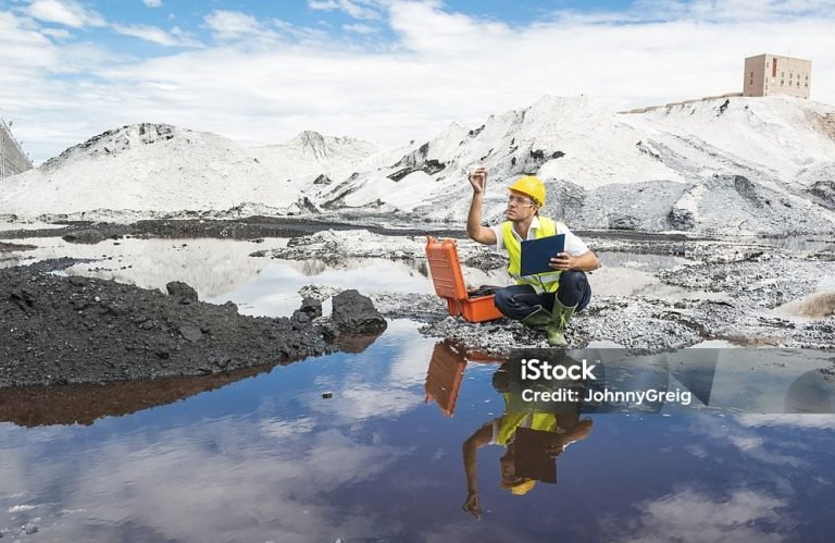
This technical advantage is particularly evident in pollution surveys: a survey of a smelter’s contaminated site showed that geophysical prospecting can complete the initial screening of an area that would take three days with traditional drilling in just two hours, and at a 60% reduction in costs.
Ⅱ. Geophysical Exploration Technology (Geophysical Exploration) System in Environmental Engineering
After a century of development, geophysical exploration has formed five major technical branches: electrical, magnetic, gravity, seismic, and radioactive. When applied to environmental engineering, adaptive innovation is required based on the characteristics of the measurement target. Taking soil and groundwater pollution investigation as an example, the three core technologies constitute a complementary system:
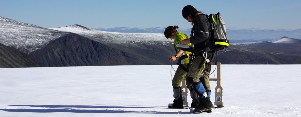
1. Electrical Resistivity Method (ERT): A “CT Scanner” for Underground Structures
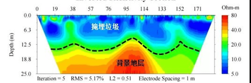
Technical features: By laying out an electrode array (inserted 20-30cm into the soil), injecting DC current into the ground and measuring the potential difference, a resistivity cross-section diagram up to 100 meters deep is formed. In a landfill case, ERT successfully distinguished the electrical difference between a 1.5-meter-thick leachate-rich layer and the bedrock.
Equipment upgrade: High-density electrical method systems (such as 84-channel arrays) can complete thousands of point measurements within 3 hours, which is 10 times more efficient than traditional running poles.
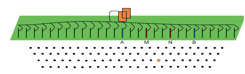
(1) Basic principles of resistivity method
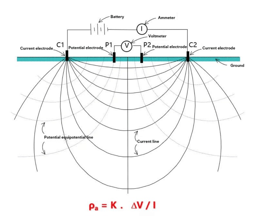
The traditional quadrupole method is also called resistivity sounding. That is, a pair of transmitting electrodes (we call them AB poles, usually called C1 and C2 poles in the figure and abroad) transmit a stable DC current into the ground, and at the same time, the receiving electrode arranged in the middle (we call them MN poles, called P1 and P2 poles in the figure and abroad) measures the potential difference between the two points, and finally calculates an apparent resistivity value through the following formula.
The K value in the formula is related to the position of the four electrodes, and there is also a formula. The apparent resistivity value calculated after measurement reflects the resistivity value at a certain depth below the center of the P1 and P2 electrodes. The depth is 1/2~1/6 of the distance from the C1 to C2 electrodes.
(2) Resistivity imaging
Based on this basic device and principle, we only need to place these four electrodes in different positions and adjust their spacing to obtain the resistivity values of the lithology at different positions and depths. If the measured points (e.g. pixels) are dense enough, we can accurately depict the resistivity cross-section of the underground strata, i.e., the tomograph.
In the actual test process, the electrodes are constantly moved, which is called pole running in the industry. The test is fast, but the pole running is slow, so the efficiency is very low. Therefore, we have optimized the design of the equipment. After all the electrodes are laid out at one time, continuous automatic measurement is carried out through intelligent exchange and switching devices, thus avoiding repeated pole running.
This is what we call electrical resistivity tomography (ERT), also known as resistivity tomography.
At present, except for a few tests that require a depth of more than a thousand meters, the high-density electrical method (ERT) can fully meet the needs of most scenarios. One electrode is used to measure a cross section, thousands or even tens of thousands of points (pixels), which usually takes 2-3 hours to complete, which is very efficient.
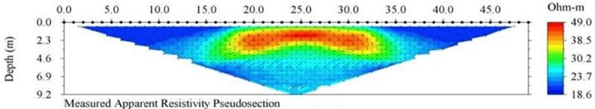
Through this method, we can get the “pseudo-section diagram” as shown in the figure below. What we directly measure here is the apparent resistivity, so we call it a “pseudo-section”. After the inversion calculation and the actual resistivity, we can get the resistivity profile diagram.

2. Ground Penetrating Radar (GPR): “High-frequency B-ultrasound” of shallow media
Working principle: It emits high-frequency electromagnetic waves (100MHz-2GHz) and identifies the medium interface based on the difference in dielectric constants. It is suitable for fine detection at a depth of 5-10 meters. In pipeline leakage detection, GPR can locate the buried position of a 0.8-meter deep pipeline with a diameter of 0.4 meters.
3. Induction electromagnetic method (EM): a “rapid screener” for plane contamination
Efficiency advantage: Real-time measurement of conductivity planar distribution, covering an area of 100,000 square meters per day, but limited by depth (15-20 meters) and susceptible to electromagnetic interference. In an oil field project, EM and ERT were used together to control the positioning error of the pollution plume boundary within ±0.5 meters.
Ⅲ. Technical principles and innovative applications of resistivity method
1. Basic measurement model
The traditional quadrupole method calculates the apparent resistivity using the formula ρ a=K⋅Δ V /I, where the device coefficient K is determined by the electrode spacing (the depth is about 1/2~1/6 of the electrode spacing). Modern inversion algorithms can convert pseudo-sections into true resistivity models. Data from a landfill site show that the RMS error can be reduced to less than 5.17% after inversion.
2. Multi-dimensional application scenarios
Cross-hole detection: Through the inter-well electrode array, the resistivity changes before and after the injection of the agent are monitored. Data from a certain remediation site showed that the conductivity change percentage after injection reached 30%, which directly reflects the diffusion effect of the agent.
Water monitoring: The integrated water surface measurement system can dynamically track river sediment pollution and achieve millimeter-level spatial matching with RTK positioning.
Technical collaboration and data verification strategy
In the face of the challenge of multiple solutions in geophysical exploration, multi-method cross-validation is required:
Parameter fusion: ERT (resistivity) and GPR (dielectric constant) were combined for analysis. In a chemical site, the two methods matched 89% of the hydrocarbon pollution.
Combination of forward and inverse modeling: The response of the abnormal body is preset through forward simulation, and compared with the measured data during inversion. In a mining area case, this method increased the accuracy of ore body positioning to 92%.
Ⅳ. Technical Analysis of Typical Cases
1. Smelter pollution plume detection
Using an ERT array with a 2-meter electrode spacing, a low-resistance anomaly area at a depth of 2-6 meters was discovered, which was verified by MIP to be a BTEX pollution zone, and the consistency rate with the resistivity pseudo-section diagram reached 85%.
The following is a set of data measured next to the smelter’s tank area, showing multiple discontinuous hydrocarbon pollution plumes at a depth of 2-6 meters.

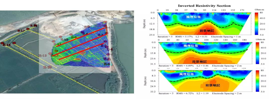
2. Landfill stratification assessment
The high-density electrical method reveals a clear interface between the landfill (low resistance) and the bedrock (high resistance). Combined with the drilling data, a three-dimensional volume model is established, and the volume calculation error is less than 3%.
The following is a cross section measured at a landfill, showing the difference between the landfill waste (low resistivity) and the underlying background strata. The layered structure is very clear.
Technology extension: Geophysical exploration technology (geophysical exploration) is currently developing towards intelligence. For example, the ERT system with integrated AI inversion algorithm can automatically identify the diffusion trend of pollution plumes. In the next article, we will explore in depth the innovative application of seismic wave method and magnetic method in deep pollution investigation.
Reference
- WIKI:https://en.wikipedia.org/wiki/Electrical_resistivity_tomography
- Society of Exploration Geophysicists (SEG) https://seg.org/
- Society of Environmental and Engineering Geophysicists (EEGS) https://www.eegs.org/
- Geology and Equipment Branch of China Mining Association http://www.chinamining.org.cn/
- International Union of Geological Sciences (IUGS) http://www.iugs.org/
- European Geological Survey Union (Eurogeosurveys) https://www.eurogeosurveys.org/