Welcome to Geotech!
-1.png)


Proton Precession Magnetometer: Working Principle, Measurement Process
Overview:A Proton Precession Magnetometer measures the Earth’s total magnetic field by detecting the precession frequency of hydrogen protons. Its operation involves polarization, field removal, signal acquisition and frequency conversion. Understanding the Proton Precession Magnetometer measurement process helps geophysical engineers evaluate survey productivity, signal quality, field interference and equipment suitability. This guide explains the instrument’s operation and practical use in magnetic surveying.

Ⅰ. What Is a Proton Precession Magnetometer?
1. Definition
A proton precession magnetometer (PPM) is a scalar magnetic instrument that measures the magnitude of an ambient magnetic field by detecting the precession frequency of protons in a hydrogen-rich sensor medium.
The instrument converts a physical frequency into a magnetic-field value. It primarily measures total magnetic-field intensity rather than individual directional components.
USGS identifies proton magnetometers as instruments for measuring total magnetic-field intensity in geomagnetic observatories. Fluxgate magnetometers are commonly used alongside them to measure vector components. USGS: Introduction to Geomagnetism.
2. What Does a PPM Measure?
A conventional PPM measures the local total magnetic-field magnitude, commonly represented by (F).
The field can be expressed as:
[
F=\sqrt{X^2+Y^2+Z^2}
]
Here, (X), (Y), and (Z) represent the orthogonal components of the magnetic field.
The instrument does not directly identify a mineral deposit or determine the direction of the field. It provides a measurement that engineers interpret alongside geological information and other survey data.
3. Where Is It Used?
PPMs have been used in:
- Ground magnetic surveys
- Geological mapping
- Mineral exploration
- Archaeological investigations
- Buried ferrous-target detection
- Geomagnetic monitoring
The suitability of a PPM depends on the target’s magnetic properties, the required sampling interval, the local field environment and the survey objective.
Ⅱ. The Physical Basis of Proton Precession
1. Proton Magnetic Moments
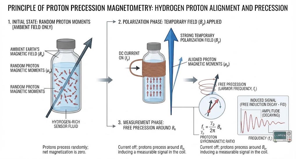
A hydrogen nucleus contains one proton. The proton has intrinsic angular momentum and an associated magnetic moment.
When the proton is placed in a magnetic field, the magnetic moment experiences a torque. Its orientation changes through a motion known as precession.
A proton-rich medium provides a large number of hydrogen nuclei. Their collective magnetic response can generate a measurable signal in the sensor coil.
2. The Larmor Relationship
The proton precession frequency is proportional to the magnitude of the ambient magnetic field.
The relationship is:
[
\omega=\gamma_p B
]
and:
[
f=\frac{\gamma_p}{2\pi}B
]
where:
- (f) is the precession frequency.
- (B) is the magnetic-field magnitude.
- (\gamma_p) is the proton gyromagnetic ratio.
- (\omega) is the angular precession frequency.
The equation allows the instrument to calculate magnetic-field intensity from the measured frequency.
USGS technical documentation describes this relationship as the basis of proton magnetometer measurements. USGS Technical Report.
3. Why Frequency-Based Measurement Matters
Frequency provides a direct link between proton behavior and magnetic-field intensity.
The instrument does not need to measure the magnetic field through a conventional voltage-to-field calibration alone. Instead, it determines the proton precession frequency and applies the gyromagnetic relationship.
However, the final result still depends on the quality of signal detection, timing, sensor design and measurement procedure.
Ⅲ. Main Components of a Proton Precession Magnetometer
1. Sensor Assembly
The sensor contains a hydrogen-rich medium and a coil system.
Depending on the design, the medium may be a suitable liquid containing hydrogen nuclei. The coil generates the temporary polarization field and detects the resulting precession signal.
Sensor construction affects signal strength, mechanical durability, handling requirements and environmental suitability.
2. Polarization Circuit
The polarization circuit supplies current to the sensor coil.
This current creates a temporary magnetic field that partially aligns proton magnetic moments.
The circuit must provide a controlled polarization stage and then remove the applied field so that the measurement stage can begin.
3. Signal Acquisition Electronics
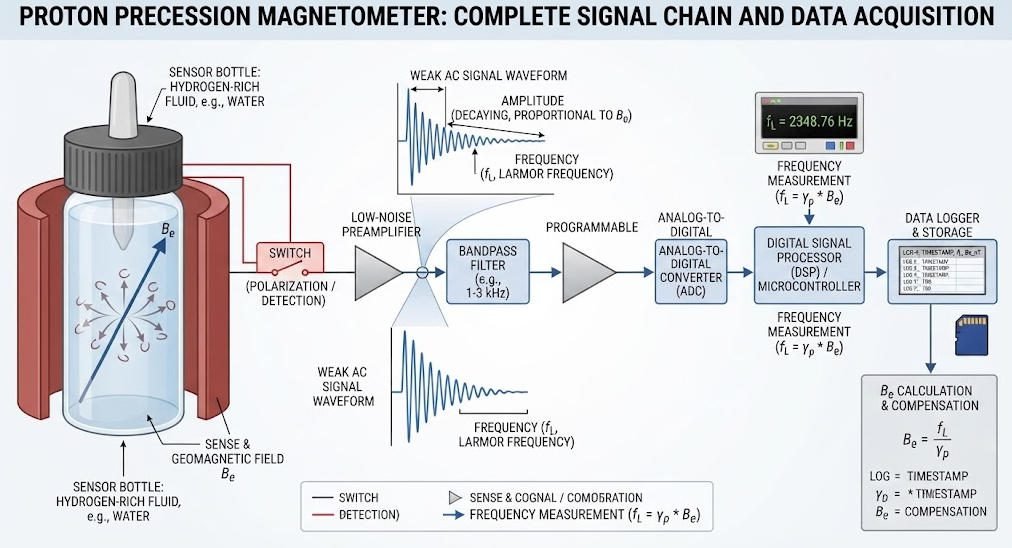
The acquisition system receives the weak electrical signal generated during proton precession.
A typical signal chain may include:
- Signal amplification
- Filtering
- Frequency detection
- Timing
- Frequency calculation
- Field conversion
- Data storage
The exact architecture varies among instruments.
4. Timing and Control System
The control system coordinates polarization, signal acquisition and data recording.
It also determines the measurement sequence and associates readings with time and, where available, position.
A stable timing reference supports reliable frequency determination, but it does not by itself guarantee the overall accuracy of the instrument.
Ⅳ. Proton Precession Magnetometer Working Principle
1. Step 1: Polarization
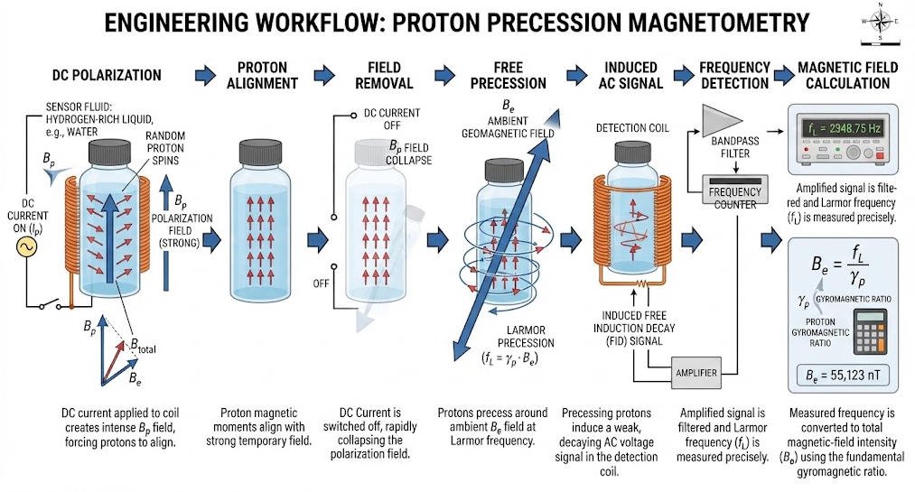
A direct current passes through the sensor coil and generates a temporary magnetic field.
The proton magnetic moments become partially aligned with the applied field.
This stage prepares the sensor for measurement. It does not yet produce the final ambient-field reading.
2. Step 2: Removal of the Polarizing Field
The instrument switches off the polarization current.
The artificial field collapses, leaving the proton system primarily influenced by the ambient magnetic field.
The timing and electrical behavior of this transition are important to the measurement cycle.
3. Step 3: Free Proton Precession
After the polarizing field is removed, the proton magnetic moments undergo free precession around the ambient field direction.
The precession frequency depends on the local magnetic-field magnitude.
This is the fundamental measurement event in a conventional free proton precession magnetometer.
4. Step 4: Signal Induction
The changing magnetic flux associated with proton precession induces a weak alternating signal in the sensor coil.
The instrument captures this signal for processing.
USGS describes the use of a coil to polarize a hydrogen-rich medium and then detect the small AC signal produced by proton precession. USGS Technical Report.
5. Step 5: Frequency Detection
The electronics process the signal and determine its precession frequency.
The system must distinguish the periodic signal from noise and interference.
Frequency detection may use different electronic or digital approaches, depending on instrument design.
6. Step 6: Magnetic-Field Calculation
The measured frequency is converted into magnetic-field intensity using the proton gyromagnetic ratio.
The instrument then records the total-field value.
7. Step 7: Data Recording
The final measurement is stored with its time stamp and, when available, GNSS position.
This enables later quality control, mapping, correction and geological interpretation.
Ⅴ. How Does a PPM Convert Frequency into Magnetic Field?
1. Frequency-to-Field Conversion
The relationship between precession frequency and magnetic-field magnitude is:
[
B=\frac{2\pi f}{\gamma_p}
]
This equation forms the basis of the instrument’s field calculation.
The measured frequency increases as the ambient magnetic field becomes stronger.
2. Illustrative Frequency Example
For a magnetic field near 50,000 nT, the proton precession frequency is approximately 2.1 kHz.
The exact value depends on the local magnetic field.
This example illustrates why accurate frequency detection is central to the instrument’s operation.
3. Measurement Units
Magnetic-field intensity may be expressed in:
- Tesla (T)
- Nanotesla (nT)
- Gamma (γ), historically equivalent to 1 nT
Geophysical magnetic survey data are commonly reported in nanotesla.
4. Total Field Is Not a Vector Measurement
A PPM measures the magnitude of the magnetic field.
It does not directly provide the individual (X), (Y), and (Z) components.
When a project requires field direction or vector changes, engineers may need a vector magnetometer or a combined measurement system.
Ⅵ. Signal Detection and Data Processing
1. Why the Signal Is Weak
The precession signal generated by the proton ensemble is typically small.
The acquisition system must detect a periodic signal in the presence of electronic noise, environmental interference and possible mechanical disturbances.
The sensor coil and electronics must therefore work as an integrated measurement system.
2. Signal Conditioning
Signal conditioning may include amplification and filtering.
These operations help isolate the useful frequency component from unwanted signals.
The appropriate filtering strategy depends on the expected signal, sensor characteristics and interference environment.
3. Frequency Estimation
The system estimates the proton precession frequency from the acquired signal.
A reliable frequency estimate is essential because the field value is calculated directly from that frequency.
Signal amplitude, frequency stability and field accuracy are related, but they are not interchangeable specifications.
4. Data Quality Checks
A field workflow may include checks for:
- Missing measurements
- Unstable signal detection
- Abnormal field jumps
- Positioning errors
- Timing inconsistencies
- Nearby magnetic interference
- Poor repeatability
The appropriate acceptance criteria depend on the survey objective and instrument specifications.
Ⅶ. Measurement Cycle and Survey Productivity
1. Why the Measurement Cycle Matters
A PPM does not necessarily provide continuous readings.
A conventional measurement cycle includes polarization, field removal, signal acquisition and frequency determination.
The total cycle time affects how many readings the operator can collect during a survey.
2. Factors Affecting Cycle Time
Cycle time may depend on:
- Polarization duration
- Signal amplitude
- Signal decay
- Frequency-detection method
- Required measurement quality
- Instrument architecture
- Field conditions
A shorter cycle can improve survey productivity, but it must still produce reliable measurements for the target anomaly.
3. Station-Based Surveys
In a station-based survey, the operator measures at planned points along survey lines.
This approach supports controlled station spacing and repeatable acquisition.
It can be useful when detailed spatial sampling is more important than continuous movement.
4. Moving Surveys
Moving surveys require coordination between measurement timing, operator movement and positioning.
If the instrument’s measurement cycle is longer than the time spent at a station, the effective spatial sampling may become too coarse.
Survey speed and station spacing should therefore be designed around the instrument’s actual measurement capability.
Ⅷ. PPM vs Other Magnetic Measurement Technologies
| Technology | Primary Output | Typical Application | Key Consideration |
|---|---|---|---|
| Proton Precession Magnetometer | Total magnetic-field magnitude | Ground magnetic surveys and reference measurements | Measurement cycle and signal acquisition |
| Overhauser Magnetometer | Total magnetic-field magnitude | High-sensitivity magnetic surveys | Different polarization mechanism |
| Fluxgate Magnetometer | Magnetic-field components | Vector measurement and continuous monitoring | Orientation and calibration |
| Cesium Vapor Magnetometer | Total magnetic-field magnitude | High-rate magnetic surveys | Sensor and system requirements |
| Other Optical Pumping Magnetometers | Total field or vector, depending on design | Specialized magnetic measurements | Technology-specific operating conditions |
These technologies serve different measurement needs.
The correct choice depends on whether the project requires total-field measurements, vector components, continuous monitoring, high sampling rates or a particular field deployment method.
Ⅸ. Proton Precession Magnetometer vs Fluxgate Magnetometer
1. Measurement Principle
A PPM derives total-field magnitude from proton precession frequency.
A fluxgate magnetometer measures magnetic-field components using a magnetic sensing core and associated electronics.
2. Output and Field Use
| Comparison | Proton Precession Magnetometer | Fluxgate Magnetometer |
|---|---|---|
| Main output | Total-field magnitude | Vector components |
| Directional information | Not directly provided | Available in suitable multi-axis systems |
| Absolute reference role | Commonly used for total-field reference | Depends on calibration and system design |
| Continuous monitoring | Depends on instrument cycle | Common in vector monitoring |
| Survey use | Ground total-field magnetic surveys | Vector surveys and monitoring |
USGS observatories use proton magnetometers for total-field measurements and triaxial fluxgate instruments for vector data. USGS Instrumentation.
Ⅹ. What Affects PPM Measurement Quality?
1. Magnetic Interference
Nearby ferrous objects can distort the local magnetic field.
Common sources include:
- Vehicles
- Steel structures
- Metal tools
- Machinery
- Buried pipelines
- Reinforced concrete
- Electrical infrastructure
The operator should identify likely interference sources before data acquisition.
2. Sensor Position
Sensor height and position influence the measured field, particularly near shallow magnetic targets.
A consistent sensor position helps improve repeatability.
For vehicle-based surveys, the sensor may need to be separated from the vehicle body to reduce magnetic contamination.
3. Temperature and Instrument Stability
Temperature can affect electronic components and measurement stability.
Instrument specifications should be evaluated across the expected field temperature range.
The sensor, electronics and timing reference should be considered as one system.
4. Signal Quality
Weak or unstable signals can make frequency estimation more difficult.
Signal quality depends on sensor design, polarization conditions, ambient field, interference and acquisition electronics.
5. Survey Geometry
Line spacing, station spacing, sensor height and positioning accuracy influence the spatial detail of a magnetic map.
A high-resolution instrument cannot compensate for a survey grid that is too coarse for the target.
Ⅺ. Field Procedure for Ground Magnetic Surveys

1. Before the Survey
Before field acquisition, engineers should:
- Define the target and expected magnetic contrast.
- Review the site’s geology and infrastructure.
- Identify possible magnetic interference sources.
- Select survey lines and station spacing.
- Confirm instrument operation and data storage.
- Establish positioning and quality-control procedures.
2. During Data Acquisition
Operators should maintain consistent sensor handling and measurement procedures.
They should record position and time where available.
Unexpected field changes should be checked against the site environment and nearby magnetic objects.
3. Base-Station Monitoring
The Earth’s magnetic field changes over time.
A base station can record temporal variations and support correction of mobile survey data.
Whether a base station is necessary depends on the survey duration, required accuracy, local field conditions and processing plan.
4. After Data Acquisition
Post-survey processing may include:
- Data validation
- Position checks
- Removal of clearly contaminated readings
- Diurnal correction, where appropriate
- Gridding
- Magnetic anomaly mapping
- Geological interpretation
Corrections should follow the survey design and documented processing procedure.
Ⅻ. Applications of Proton Precession Magnetometers
1. Mineral Exploration
Magnetic surveys can map variations associated with magnetic minerals, rock units and geological structures.
A PPM measures the magnetic response, not the mineral deposit itself.
Interpretation requires geological context and, where appropriate, integration with other geophysical methods.
2. Geological Mapping
Total-field magnetic data can support mapping of lithological boundaries and structural trends.
The value of the data depends on magnetic contrast and survey coverage.
3. Archaeological Investigation
Magnetic surveys can detect anomalies associated with buried structures, fired materials and ferrous objects.
Detection depends on target properties, depth, soil conditions, cultural noise and survey design.
4. Engineering and Environmental Surveys
Magnetic methods can help locate buried ferrous objects and infrastructure.
Potential targets include pipelines, tanks, abandoned wells and other metallic structures.
The method is most useful when the target creates a measurable magnetic contrast with the surrounding environment.
5. Geomagnetic Monitoring
Proton magnetometers have been used to monitor changes in total magnetic-field intensity.
USGS documents the use of proton precession instruments in long-term magnetic monitoring networks. USGS Monitoring Review.
ⅩⅢ. How to Select a Proton Precession Magnetometer
1. Start With the Survey Objective
The instrument should match the intended measurement.
For example:
- Total-field geological mapping requires reliable scalar measurements.
- Vector monitoring requires directional information.
- High-density surveys require an appropriate measurement cycle and positioning workflow.
- Gradient surveys require a suitable multi-sensor arrangement or another gradient measurement method.
2. Evaluate the Core Specifications
| Specification | Meaning | Engineering Relevance |
|---|---|---|
| Sensitivity | Ability to detect small field changes | Weak anomaly measurement |
| Resolution | Smallest represented increment | Numerical data granularity |
| Accuracy | Agreement with a reference value | Absolute field measurement |
| Repeatability | Consistency under repeated conditions | Survey quality control |
| Sampling interval | Time between readings | Spatial or temporal sampling |
| Dynamic range | Supported field range | Compatibility with local field |
| Temperature range | Operating environment | Field deployment |
| Positioning support | Time and location association | Mapping and correction |
| Sensor configuration | Single or multiple sensors | Total-field or gradient workflow |
These specifications should be evaluated together.
A fine display increment does not automatically establish high sensitivity or absolute accuracy.
3. Single-Sensor or Dual-Sensor Configuration
A single-sensor instrument is suitable for conventional total-field measurement.
A dual-sensor arrangement can support gradient-oriented workflows by comparing field values at two sensor positions.
The appropriate configuration depends on the target, survey geometry, expected background variation and processing requirements.
4. Match Sampling to Target Size
Small or shallow targets may require tighter station spacing.
Larger regional structures may permit wider spacing.
The survey design should account for target dimensions, expected anomaly shape, instrument cycle time and positioning accuracy.
ⅩⅣ. Geotech JPMG Proton Magnetometer
Geotech offers JPMG proton magnetometer configurations for field magnetic surveying.
The company’s product pages describe single-sensor and dual-sensor systems. The appropriate configuration depends on the measurement objective and survey design.
1. Single-Sensor Configuration
A single-sensor configuration supports conventional total-field magnetic measurements.
It can be considered for geological mapping, mineral exploration and other surveys that require scalar magnetic-field data.
2. Dual-Sensor Configuration
A dual-sensor configuration can support magnetic-gradient workflows when measurements from two sensor positions are compared.
The sensor spacing and processing method should be selected according to the target and survey requirements.
3. Application Considerations
Potential applications include:
- Mineral exploration
- Geological mapping
- Archaeological surveys
- Buried ferrous-target detection
- Engineering geophysics
- Magnetic gradient surveys
Actual performance depends on field conditions, survey design, instrument configuration and data-processing procedures.
Product references:
ⅩⅤ. Integrating PPM Data With Other Geophysical Methods
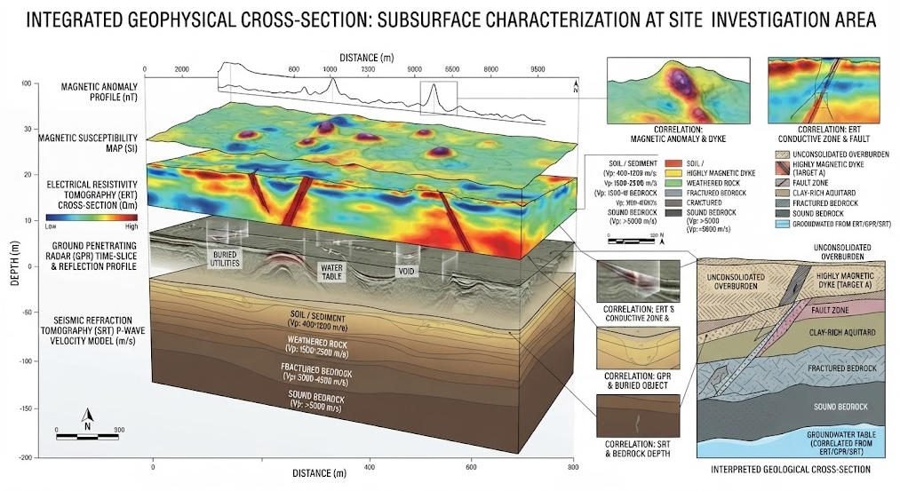
1. Magnetic Data Provide One Physical Property
Magnetic surveys respond to variations in magnetic properties.
They do not directly measure electrical resistivity, chargeability, dielectric permittivity or seismic velocity.
Therefore, magnetic data may need to be combined with other methods when the target requires multiple physical-property constraints.
2. Complementary Methods
| Method | Main Physical Property | Potential Role Alongside Magnetic Survey |
|---|---|---|
| ERT | Electrical resistivity | Mapping resistivity contrasts |
| IP | Chargeability and related electrical response | Investigating polarizable materials |
| GPR | Dielectric contrasts | Shallow structural imaging |
| Seismic | Elastic-wave response | Mapping interfaces and mechanical contrasts |
| EM | Electromagnetic response | Conductivity-related investigation |
| VES | Vertical variation in apparent resistivity | Electrical sounding |
The best combination depends on geology, target depth, site access and project objectives.
3. Integrated Interpretation
Magnetic anomalies should be compared with geological maps, topography and relevant geophysical datasets.
Integration can help distinguish competing interpretations.
However, the addition of multiple datasets does not automatically guarantee a unique geological solution.
ⅩⅥ. Common Misunderstandings
1. “A PPM Directly Detects Mineral Deposits”
A PPM measures magnetic-field intensity.
Geological interpretation identifies possible sources of the observed anomalies.
2. “Resolution Equals Accuracy”
Resolution is the smallest numerical increment represented by the instrument.
Accuracy describes agreement with a reference value.
They are different performance characteristics.
3. “Every Magnetic Anomaly Is Geological”
Anomalies may originate from natural geology, buried infrastructure, vehicles, metal objects or other cultural sources.
Field context and quality control are essential.
4. “A Single Reading Is Enough to Confirm a Target”
A single measurement rarely provides enough spatial information for reliable interpretation.
Survey lines, repeat measurements, background assessment and geological context are often needed.
ⅩⅦ. Practical Checklist for Field Engineers
Before mobilization:
- Confirm the target and survey objective.
- Select suitable sensor configuration.
- Review expected field conditions.
- Plan line spacing and station spacing.
- Check positioning and time recording.
- Identify likely magnetic interference sources.
- Confirm instrument operation and data storage.
During acquisition:
- Maintain consistent sensor geometry.
- Follow the planned measurement cycle.
- Record position and time.
- Check abnormal readings.
- Keep magnetic objects away from the sensor.
- Repeat questionable measurements where practical.
After acquisition:
- Validate measurement records.
- Check positioning and timing.
- Apply appropriate temporal corrections.
- Review possible cultural interference.
- Generate magnetic anomaly maps.
- Interpret results with geological and complementary geophysical data.
ⅩⅧ. Conclusion
A proton precession magnetometer measures total magnetic-field intensity by converting proton precession frequency into a magnetic-field value.
Its measurement chain includes polarization, removal of the artificial field, free proton precession, signal induction, frequency detection, field calculation and data recording.
For geophysical engineers, understanding this chain helps explain how instrument specifications affect survey productivity and data quality.
Reliable results require more than a sensitive sensor. Survey geometry, magnetic interference, timing, signal quality, positioning and processing must also be controlled.
The correct instrument configuration should therefore be selected according to the target, required measurement output and field conditions.
Related Articles
| Title | Core Content | URL |
|---|---|---|
| How Proton Precession Works in Measurement | Explains the physical relationship between proton precession frequency and magnetic-field measurement. | https://geotechcn.net/service/how-proton-precession-works-in-measurement/ |
| Proton Magnetometer: From Hydrogen Atom Polarization to Accurate Magnetic Field Measurement | Covers proton polarization, free precession and frequency-to-field conversion. | https://geotechcn.net/service/proton-magnetometer-from-hydrogen-atom-polarization-to-accurate-magnetic-field-measurement/ |
| Proton Magnetometer Signal Processing | Discusses signal acquisition and processing in proton magnetometer systems. | https://geotechcn.net/service/proton-magnetometer-signal-processing/ |
| Modulation of a Proton Magnetometer Signal Due to Rotation | Examines rotation-related signal modulation and measurement considerations. | https://geotechcn.net/service/modulation-of-a-proton-magnetometer-signal-due-to-rotation/ |
| Proton Magnetometer Insights | Provides broader information on proton magnetometer technology and applications. | https://geotechcn.net/service/proton-magnetometer-insights/ |
| Dual-Sensor Proton Magnetometer | Product information for dual-sensor proton magnetic measurement and gradient-oriented workflows. | https://geotechcn.net/products/magnetic-instrument/dual-sensor-proton-magnetometer/ |
| Single-Sensor Proton Magnetometer | Product information for single-sensor total-field magnetic measurement. | https://geotechcn.net/products/magnetic-instrument/proton-magnetometer-single/ |
Reference Sources
| Title | Core Content | URL |
|---|---|---|
| Introduction to Geomagnetism — USGS | Explains total magnetic-field intensity and the role of proton precession magnetometers in geomagnetic observatories. | https://www.usgs.gov/programs/geomagnetism/introduction-geomagnetism |
| Instrumentation — USGS Geomagnetism Program | Describes the use of proton magnetometers for total-field measurements and fluxgate systems for vector data. | https://www.usgs.gov/programs/geomagnetism/science/instrumentation |
| Proton Magnetometer Technical Report — USGS | Provides the proton precession equation, polarization mechanism and frequency-based field calculation. | https://pubs.usgs.gov/of/1981/1346/report.pdf |
| Magnetic Method — U.S. EPA | Explains magnetic survey applications and the use of magnetic measurements in environmental and engineering investigations. | https://www.epa.gov/environmental-geophysics/magnetic-method |
| Review of Magnetic Field Monitoring — USGS | Documents the use of proton precession magnetometers for long-term total-field monitoring. | https://www.usgs.gov/publications/review-magnetic-field-monitoring-near-active-faults-and-volcanic-calderas-california |
FAQ
Q1. What is a proton precession magnetometer?
A proton precession magnetometer is a scalar magnetic instrument that measures total magnetic-field intensity by detecting the precession frequency of protons in a hydrogen-rich sensor. The instrument polarizes the protons, removes the artificial field and measures their free-precession signal. It is used in ground magnetic surveying, geological mapping and geomagnetic monitoring.
Q2. How does a proton precession magnetometer work?
A proton precession magnetometer applies a temporary magnetic field to polarize hydrogen protons. After the field is removed, the protons precess around the ambient magnetic field and induce a weak electrical signal. The instrument measures the signal frequency and converts it into total magnetic-field intensity using the proton gyromagnetic ratio.
Q3. What is the difference between a proton magnetometer and a fluxgate magnetometer?
A proton precession magnetometer primarily measures total magnetic-field magnitude. A fluxgate magnetometer measures magnetic-field components and can provide directional information when configured as a multi-axis system. The two technologies serve different purposes and are often used together in geomagnetic observatories and specialized survey systems.
Q4. What affects the accuracy of a proton precession magnetometer?
Measurement quality depends on signal detection, frequency estimation, timing stability, sensor design, temperature, magnetic interference and field procedures. Sensor position, survey geometry and data correction also matter. Engineers should evaluate accuracy, sensitivity, resolution and repeatability separately rather than treating them as interchangeable specifications.
Q5. How is a proton precession magnetometer used in mineral exploration?
A proton precession magnetometer measures spatial variations in total magnetic-field intensity. Geophysicists use these variations to map magnetic anomalies that may reflect magnetic rock units, structures or mineralization. The instrument does not directly identify ore. Geological interpretation requires suitable survey coverage, knowledge of local geology and, where appropriate, complementary geophysical data.