Welcome to Geotech!


IP Receiver: Principles, Types, Applications and Selection Guide
Overview:An IP Receiver is a geophysical instrument designed to measure electrical potential responses during induced polarization surveys, helping characterize subsurface chargeability and electrical behavior. A Resistivity Receiver measures voltage differences used to calculate apparent resistivity and support subsurface imaging. Understanding the functions, measurement principles, and selection criteria of an Induced Polarization Receiver helps survey teams choose compatible equipment for mineral exploration, groundwater investigation, and engineering geophysics.

Ⅰ. What Is an IP Receiver?
1. Definition of an IP Receiver
An IP Receiver, or Induced Polarization Receiver, is a geophysical instrument used to measure electrical potential signals generated during induced polarization (IP) surveys. It records the voltage response of the ground after or during the application of an electrical current through current electrodes.
The collected data can be used to evaluate electrical resistivity and polarization-related properties, depending on the survey method and receiver configuration.
In time-domain IP (TDIP), the receiver measures voltage decay after the transmitter current is switched off. In frequency-domain IP (FDIP), it measures changes in amplitude and phase between applied current and the resulting voltage response.
An IP Receiver is therefore more than a conventional voltage-measuring device. It must support the signal acquisition, timing, and data-quality requirements of the selected IP method.
2. What Is a Resistivity Receiver?
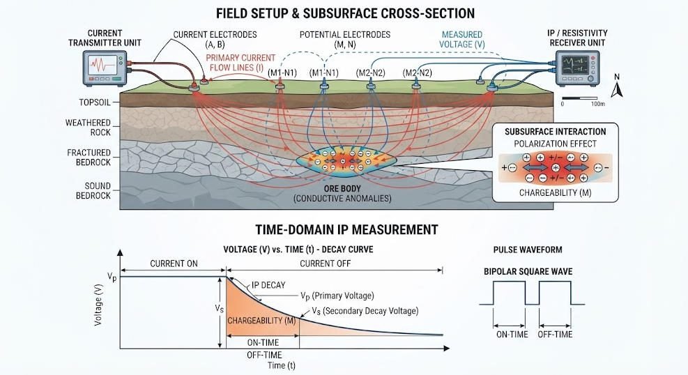
A Resistivity Receiver is an instrument that measures electrical potential differences in the ground during electrical resistivity surveys.
In a typical direct-current (DC) resistivity survey, current is injected into the ground through current electrodes. Potential electrodes measure the resulting voltage difference. Combined with the electrode geometry and current information, these measurements are used to calculate apparent resistivity.
Resistivity data can help identify contrasts between geological materials, such as differences associated with lithology, saturation, porosity, fractures, and conductive or resistive zones.
A resistivity receiver may be a dedicated instrument or part of an integrated resistivity and IP system.
3. What Is an Induced Polarization Receiver?
An Induced Polarization Receiver is designed to measure polarization-related electrical responses in subsurface materials.
When electrical current passes through certain geological materials, charge accumulates at mineral-fluid interfaces and other microscopic boundaries. After the current is interrupted, part of the electrical response may decay over time. This behavior is known as induced polarization.
The receiver records the voltage response and, depending on the system, calculates or stores parameters such as:
- Primary voltage.
- Secondary voltage.
- Chargeability.
- Apparent resistivity.
- Decay-curve data.
- Phase or frequency-dependent response.
The specific parameters depend on whether the equipment supports time-domain IP, frequency-domain IP, spectral IP, or a combination of methods.
Ⅱ. How Does an IP Receiver Work?
1. Basic Measurement Process
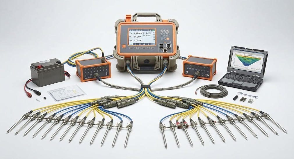
A typical IP survey uses a transmitter, current electrodes, potential electrodes, a receiver, and data-processing software.
The transmitter injects controlled electrical current into the ground. The receiver measures voltage responses through the potential-electrode array. The recorded data are then processed to derive electrical properties and generate geophysical models.
A simplified workflow is:
- The transmitter injects current into the ground.
- The current creates an electrical field in the subsurface.
- Potential electrodes detect the voltage response.
- The receiver amplifies, filters, and digitizes the signal.
- The system records the measurement and relevant acquisition parameters.
- Software processes the data for interpretation and inversion.
The receiver’s measurement quality depends on electrode contact, electrical noise, system synchronization, instrument stability, and the selected acquisition settings.
2. Time-Domain IP Measurement
In time-domain IP, the transmitter applies current for a defined period and then switches it off. The receiver measures the voltage decay during a specified sampling window.
The decay response reflects polarization effects in the ground. Chargeability is commonly derived from the relationship between the secondary voltage and the primary voltage, or from a time-integrated decay response, depending on the instrument and measurement convention.
A simplified expression for average chargeability is:
M=Vp(t2−t1)1∫t1t2Vs(t)dt
Where:
- M is average chargeability under the stated convention.
- Vp is the primary voltage reference.
- Vs(t) is the measured secondary voltage during the selected time window.
- t1 and t2 define the integration interval.
Different systems may use different units, normalization methods, and sampling windows. Survey reports should therefore specify the measurement convention.
3. Frequency-Domain IP Measurement
In frequency-domain IP, electrical current is applied at one or more frequencies. The receiver measures the amplitude and phase of the resulting voltage response.
Polarization can produce a frequency-dependent response, including phase shifts between the injected current and measured voltage.
Frequency-domain measurements are useful when the survey objective requires characterization of frequency-dependent electrical properties. Spectral IP systems may measure responses across multiple frequencies to investigate subsurface polarization behavior in greater detail.
4. Resistivity Measurement
A resistivity receiver measures the potential difference generated by current flowing through the ground.
For a common four-electrode configuration, apparent resistivity is calculated using:
ρa=KIΔV
Where:
- ρa is apparent resistivity.
- K is the geometric factor determined by electrode arrangement.
- ΔV is the measured potential difference.
- I is the injected current.
The geometric factor varies with the electrode array, such as Wenner, Schlumberger, or dipole-dipole configurations.
Apparent resistivity is not necessarily the true resistivity of a specific geological layer. In imaging surveys, multiple measurements are combined and inverted to estimate the spatial distribution of subsurface resistivity.
Ⅲ. IP Receiver vs. Resistivity Receiver
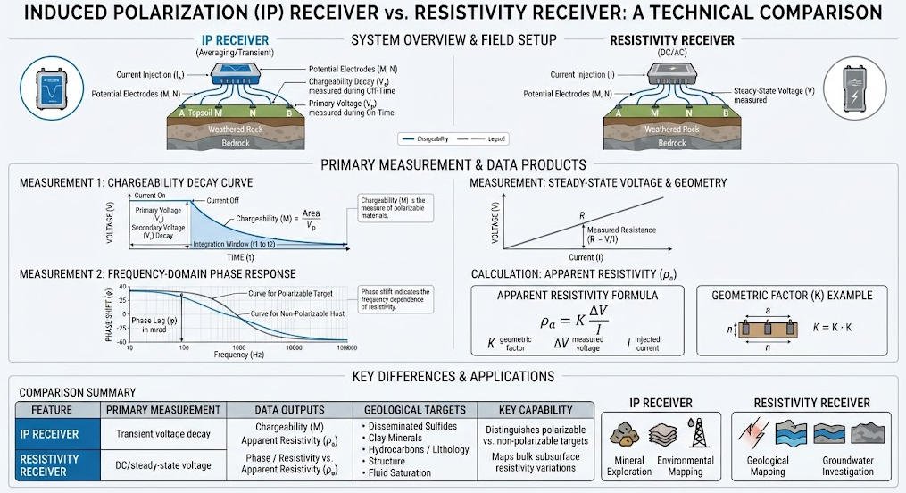
1. Key Differences
Although IP and resistivity receivers share some measurement functions, their data-acquisition requirements are not identical.
| Comparison | IP Receiver | Resistivity Receiver |
|---|---|---|
| Primary objective | Measure polarization-related responses | Measure electrical potential for resistivity calculation |
| Typical data | Chargeability, decay curve, voltage, phase | Voltage, apparent resistivity |
| Time-domain capability | Measures voltage decay after current interruption | Usually focuses on stable voltage response during current injection |
| Frequency-domain capability | May measure phase and amplitude across frequencies | Depends on instrument design |
| Signal requirements | Often needs stable low-noise acquisition of weak decay signals | Requires accurate and stable voltage measurement |
| Common applications | Mineral exploration, disseminated sulfide investigation, environmental studies | Groundwater, engineering, environmental and geological surveys |
| System configuration | Often integrated with a transmitter and synchronized acquisition system | Dedicated or integrated resistivity system |
2. Can One Receiver Perform Both IP and Resistivity Measurements?
Yes. Many modern geophysical systems integrate resistivity and IP measurement functions in one receiver or acquisition platform.
An integrated system may collect:
- Voltage measurements for resistivity calculations.
- Time-domain IP decay data.
- Chargeability values.
- Multiple electrode configurations.
- Multi-channel measurements, depending on system design.
However, not every resistivity receiver supports IP acquisition. A receiver intended for IP surveys must be compatible with the required current waveform, measurement timing, signal range, and data-processing workflow.
Before selecting a combined system, confirm that its hardware and software support the intended IP mode and resistivity configuration.
Ⅳ. Main Types of IP and Resistivity Receivers
1. Single-Channel Receiver
A single-channel receiver measures one potential channel at a time.
It may be suitable for:
- Small-scale surveys.
- Educational and research applications.
- Electrical sounding.
- Field verification and supplementary measurements.
- Projects where acquisition speed is not the main priority.
Its straightforward configuration can be useful for flexible field deployment, but large surveys may require more measurement time.
2. Multi-Channel IP Receiver
A multi-channel IP receiver measures multiple potential channels within one acquisition cycle, subject to its channel architecture and electrode configuration.
Potential advantages include:
- Reduced acquisition time for suitable survey layouts.
- Simultaneous or coordinated measurement of multiple voltage channels.
- Improved field productivity.
- More efficient data collection for multi-electrode surveys.
Actual productivity depends on the number of channels, switching architecture, electrode layout, contact conditions, and survey protocol.
3. Distributed Receiver System
A distributed system uses multiple acquisition units or measurement modules connected across a survey area.
Such systems may be suitable for large-scale electrical imaging projects that require flexible electrode deployment or distributed data acquisition.
When evaluating a distributed receiver system, check communication reliability, synchronization, channel capacity, power supply, field setup, and data-management requirements.
4. Integrated Resistivity and IP Receiver
An integrated resistivity and IP receiver combines electrical potential measurement with polarization-response acquisition.
This configuration can support projects that require both resistivity and chargeability information, such as mineral exploration and subsurface characterization.
The actual capabilities vary by model. Confirm the supported IP mode, voltage range, sampling windows, electrode switching compatibility, and software functions before purchase.
Ⅴ. Technical Specifications: What Should You Evaluate?
The specifications of an IP Receiver or Resistivity Receiver should be evaluated against the survey objectives and expected field conditions rather than by a single headline number.
| Specification | Why It Matters | What to Verify |
|---|---|---|
| Voltage measurement range | Determines the range of signals the receiver can measure | Input range, gain settings, overload behavior |
| Measurement resolution | Affects the ability to distinguish small voltage changes | Digital resolution and effective measurement performance |
| Accuracy and stability | Influences the reliability of measured voltage values | Accuracy specifications, drift, calibration |
| Input impedance | Helps limit loading of the potential-electrode circuit | Input impedance and electrode compatibility |
| Noise performance | Important for weak signals and low-voltage conditions | Noise specifications and field performance |
| IP sampling windows | Determines how decay responses are recorded | Number, duration, and timing of sampling windows |
| Channel count | Influences acquisition layout and productivity | Number of simultaneous channels and switching design |
| Synchronization | Important for coordinated transmitter-receiver measurements | Timing accuracy and synchronization method |
| Data storage and export | Affects field workflow and post-processing | File formats, metadata, software compatibility |
| Environmental protection | Influences suitability for field conditions | Operating temperature, ingress protection, ruggedness |
1. Voltage Range and Resolution
The receiver must accommodate the expected potential differences without frequent overload or insufficient signal resolution.
A wide measurement range can help accommodate varying field conditions, but a wide range alone does not guarantee high-quality measurements. Effective resolution, noise, gain control, and stability also matter.
2. Input Impedance and Electrode Contact
High input impedance helps reduce the influence of the receiver on the measured potential circuit. However, poor electrode contact can still produce unstable readings, elevated noise, or measurement errors.
Field teams should evaluate electrode contact resistance, cable integrity, electrode polarization, and local ground conditions.
3. Noise and Signal Stability
Electrical noise can arise from power infrastructure, industrial equipment, telluric variations, poor electrode contact, and cable coupling.
For IP measurements, noise is particularly important when the secondary voltage is weak relative to the primary voltage or when the decay signal approaches the background noise level.
Noise performance should be evaluated alongside the survey’s expected signal strength and field environment.
Ⅵ. Applications of IP Receivers and Resistivity Receivers
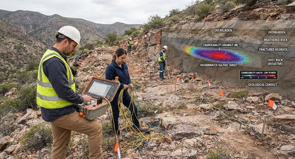
1. Mineral Exploration
IP receivers are widely used in mineral exploration to measure chargeability and resistivity contrasts associated with geological structures and mineralization.
They may support investigations of disseminated sulfide mineralization and other targets that produce measurable polarization responses.
Resistivity data provide complementary information about electrical contrasts, helping geophysicists interpret the geological context.
Neither high chargeability nor low resistivity uniquely identifies a particular ore body. Interpretation requires geological information, survey design, and appropriate modeling.
2. Groundwater Exploration
Resistivity receivers are used to investigate subsurface electrical contrasts that may relate to groundwater-bearing formations, weathered zones, fractures, and changes in saturation.
IP measurements may provide additional information in selected geological settings.
Electrical methods do not directly measure groundwater yield or guarantee the presence of a productive aquifer. Results should be integrated with geological mapping, drilling information, and other relevant evidence.
3. Environmental Investigation
Resistivity and IP surveys can support environmental investigations involving landfill boundaries, leachate-related contrasts, contaminated ground, and subsurface heterogeneity.
The electrical response of a target depends on factors such as fluid conductivity, porosity, saturation, clay content, and mineral composition. Electrical anomalies should therefore be treated as indirect evidence rather than definitive chemical identification.
4. Engineering and Geotechnical Surveys
Electrical resistivity measurements can help characterize subsurface variations relevant to engineering investigations, including weathered zones, fractured rock, and possible cavities under suitable conditions.
IP data may provide complementary information where polarization contrasts are relevant.
These methods are commonly used alongside borehole data, seismic methods, geological mapping, and other site-investigation techniques.
Ⅶ. How to Select an IP Receiver or Resistivity Receiver
1. Define the Survey Objective
Start by identifying the physical property you need to measure.
- For resistivity imaging, prioritize stable voltage measurement, electrode-array compatibility, and data-processing support.
- For time-domain IP, verify decay-curve acquisition, sampling windows, and chargeability calculation.
- For frequency-domain IP, verify amplitude and phase measurement at the required frequencies.
- For combined surveys, confirm that the receiver supports both resistivity and the required IP method.
2. Match the Receiver to the Transmitter
The receiver and transmitter must be compatible in terms of current waveform, timing, operating mode, and system communication.
For IP surveys, verify:
- Transmitter-receiver synchronization.
- Current-on and current-off timing.
- Supported pulse duration and repetition cycle.
- Receiver input range and protection.
- Data acquisition and interpretation compatibility.
A receiver’s ability to measure voltage does not automatically mean it can perform all IP acquisition modes.
3. Evaluate Survey Scale and Channel Requirements
| Survey Requirement | Receiver Considerations |
|---|---|
| Small field survey | Single-channel or compact integrated system |
| Multi-electrode imaging | Multi-channel capacity and electrode switching |
| Large survey area | Distributed acquisition and communication reliability |
| Mineral exploration | IP capability, low-noise acquisition, chargeability processing |
| Groundwater investigation | Resistivity measurement stability and suitable electrode arrays |
| Combined IP and resistivity | Integrated acquisition and compatible processing software |
4. Assess Software and Data Compatibility
Receiver hardware is only one part of a geophysical acquisition workflow.
Before purchasing, confirm that the system can export data in formats supported by the processing and inversion software used by your team.
Review electrode-position records, measurement metadata, quality-control functions, and the ability to identify poor-quality readings.
5. Consider Field Support and Long-Term Operation
Field equipment must remain reliable under practical operating conditions.
Consider:
- Training and technical support.
- Calibration and maintenance requirements.
- Replacement cables and electrodes.
- Battery or power requirements.
- Firmware and software updates.
- Warranty and service arrangements.
- Compatibility with existing equipment.
Ⅷ. Field Workflow and Data Quality Control
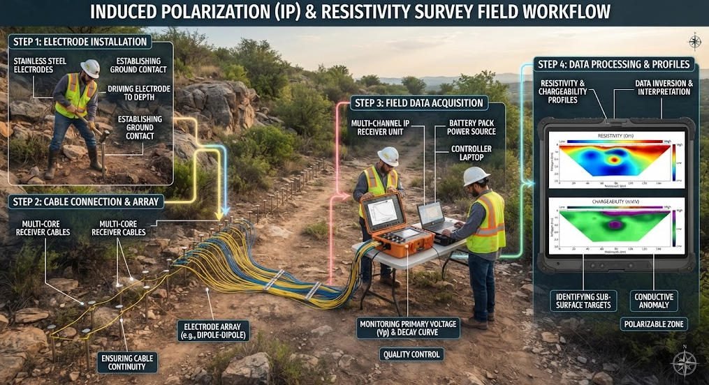
1. Pre-Survey Preparation
Before deployment, verify the survey design, electrode positions, array configuration, receiver settings, and transmitter compatibility.
Inspect cables, connectors, electrodes, batteries, and communication interfaces. Confirm that the measurement parameters match the project requirements.
2. Electrode Installation and Contact Checks
Install the electrodes according to the selected array and site conditions.
Check contact quality before starting acquisition. Where contact is poor, improve electrode installation or use an appropriate contact-enhancement procedure consistent with the survey protocol and environmental requirements.
3. Data Acquisition
During acquisition, monitor:
- Measured voltage and current values.
- Contact-related warnings.
- Noise levels and unstable readings.
- Channel status.
- Synchronization and communication.
- Repeated measurements where quality control requires them.
4. Quality Control and Processing
After acquisition, review data completeness, anomalous readings, repeated measurements, and electrode-position records.
For IP data, inspect decay curves and chargeability consistency where available. For resistivity data, review voltage stability, current information, and apparent-resistivity patterns.
Data inversion should be performed only after appropriate quality control. An inversion model is an interpretation of the measurements, not a direct photograph of the subsurface.
Ⅸ. Common Problems and Troubleshooting
| Problem | Possible Cause | Recommended Check |
|---|---|---|
| Unstable voltage readings | Poor electrode contact, noise, loose connections | Check electrodes, cables, grounding conditions, and noise sources |
| Weak IP decay signal | Low signal strength, unsuitable sampling window, high noise | Review survey parameters, contact quality, and acquisition settings |
| Frequent overload | Signal exceeds input range or gain is unsuitable | Verify input range and gain configuration |
| Inconsistent measurements | Changing contact conditions, unstable current, environmental noise | Repeat measurements and inspect current and voltage records |
| Missing channels | Cable or switching issue, communication failure | Check channel connections, switching configuration, and system status |
| Unexpected resistivity values | Incorrect geometry factor, electrode positions, or current data | Verify array configuration and measurement metadata |
Ⅹ. Geotech Receiver Systems and Related Equipment
For projects involving resistivity and induced polarization measurements, equipment selection should consider the complete acquisition chain: transmitter, receiver, electrode system, cables, positioning, and processing software.
Geotech’s electrical exploration product range includes equipment and systems for resistivity and IP applications. Users should confirm the exact receiver functions, channel configuration, transmitter compatibility, and supported acquisition modes for the selected model.
Relevant product and technical resources:
- High Power IP System
- High Power IP System – Related Configuration
- WDA-1 DC Meter
- WGMD-9 Distributed System
- What Are Resistivity Meters?
- Electrical Imaging: ERT and VES
- Induced Polarization Method Guide
Important: Product-specific channel counts, voltage ranges, noise levels, IP modes, and other technical parameters should be verified against the latest official datasheet for the exact model.
Ⅺ. Conclusion
An IP Receiver measures polarization-related electrical responses, while a Resistivity Receiver measures potential differences used to calculate apparent resistivity. An Induced Polarization Receiver may also support resistivity measurements when the system is designed for combined acquisition.
Choosing the right equipment requires more than comparing channel counts or measurement ranges. Survey objectives, transmitter compatibility, signal quality, electrode configuration, data-processing support, and field conditions all influence the suitability of a receiver.
For mineral exploration, groundwater investigation, environmental studies, and engineering geophysics, a well-matched receiver system helps produce consistent electrical measurements and supports more reliable subsurface interpretation.
Related Articles
| Anchor Text | Target URL | Recommended Placement |
|---|---|---|
| High Power IP System | https://geotechcn.net/products/electrical-instrument/high-power-ip-system/ | Equipment section |
| High Power IP System Configuration | https://geotechcn.net/products/electrical-instrument/high-power-ip-system-2/ | System compatibility |
| WDA-1 DC Meter | https://geotechcn.net/products/electrical-instrument/wda-1-dc-meter/ | Resistivity measurement |
| WGMD-9 Distributed System | https://geotechcn.net/products/electrical-instrument/wgmd-9-distributed-system/ | Distributed systems |
| What Are Resistivity Meters? | https://geotechcn.net/service/what-are-resistivity-meters/ | Resistivity principles |
| Electrical Imaging: ERT and VES | https://geotechcn.net/service/electrical-imaging-ert-ves/ | Resistivity imaging |
| Induced Polarization Method | https://geotechcn.net/service/induced-polarization-ip/ | IP principles |
| Geophysical Surveying Explained | https://geotechcn.net/service/geophysical-surveying-explained/ | Applications |
Reference Sources
| Source | Reference Topic | URL |
|---|---|---|
| U.S. EPA | Induced Polarization and Complex Resistivity | https://www.epa.gov/environmental-geophysics |
| U.S. EPA | Electrical Resistivity | https://www.epa.gov/environmental-geophysics |
| British Geological Survey (BGS) | Geophysical Survey Methods | https://www.bgs.ac.uk/ |
| U.S. Geological Survey (USGS) | Geophysical Methods and Applications | https://www.usgs.gov/ |
FAQ
Q1. What is an IP Receiver?
An IP Receiver is a geophysical instrument that measures electrical potential responses during induced polarization surveys. Depending on its design, it can record voltage decay, calculate chargeability, and support resistivity measurements. It is commonly used in mineral exploration and other investigations where polarization-related electrical properties help characterize subsurface materials.
Q2. What is the difference between an IP Receiver and a Resistivity Receiver?
A Resistivity Receiver measures voltage differences used to calculate apparent resistivity. An IP Receiver measures polarization-related responses, such as voltage decay or phase changes. Some integrated systems support both functions, but not every resistivity receiver can perform IP measurements. The required acquisition mode should be verified before equipment selection.
Q3. Can an Induced Polarization Receiver measure resistivity?
Yes, an Induced Polarization Receiver may also measure resistivity when the system supports both functions. Integrated systems can collect voltage data for apparent-resistivity calculations and polarization-related measurements such as chargeability. Whether both functions are available depends on the receiver’s hardware, acquisition software, and compatibility with the transmitter.
Q4. What specifications matter most when selecting an IP Receiver?
Important specifications include voltage range, measurement resolution, accuracy, input impedance, noise performance, channel count, synchronization, and IP sampling capabilities. For time-domain surveys, the receiver should support the required decay-curve sampling windows. For frequency-domain surveys, verify amplitude and phase measurement capabilities across the required frequencies.
Q5. Where are IP Receivers and Resistivity Receivers used?
These receivers are used in mineral exploration, groundwater investigation, environmental assessment, and engineering geophysics. IP measurements can help identify polarization contrasts, while resistivity data reveal electrical-property variations. Both methods provide indirect subsurface information and should be interpreted alongside geological, geochemical, borehole, or other relevant survey data.