Welcome to Geotech!
-1.png)


What is Electrical Resistivity Tomography Instrument?丨ERT Instrument Guide
TIPS:ERT instrument selection determines whether your geophysical survey succeeds or fails. This guide explains how ERT instrument hardware specs — A/D resolution, channel count, and dynamic range — directly impact data quality. Learn to match Geotech GIM systems to your project needs.
Ⅰ. Why Hardware Specs Determine Survey Success
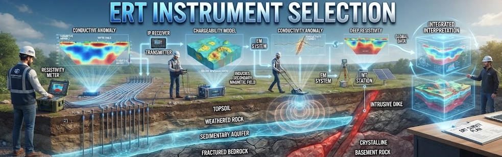
An ERT instrument is more than a box with buttons. It is the bridge between raw geology and actionable data. The wrong instrument produces noisy, shallow, or misleading images. The right instrument reveals structures that drilling would miss.
Field studies by Parsekian et al. tested six commercial ERT instruments side by side. All used the same electrode line. All ran the same array sequence. Yet contact resistance above 2.6 kΩ degraded data quality differently on each unit. Instruments with higher transmitter current maintained accuracy where low-current units failed. This proves one fact: hardware specs are not marketing numbers. They determine what you can and cannot see underground.
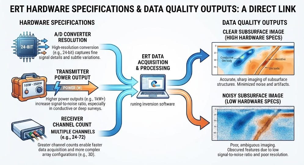
This article decodes the specs that matter. You will learn how A/D resolution, channel count, dynamic range, and transmitter power translate into real field performance. You will also see how Geotech’s GIM Series stacks up against these benchmarks.
Ⅱ. Core Hardware Components: What Each Part Does
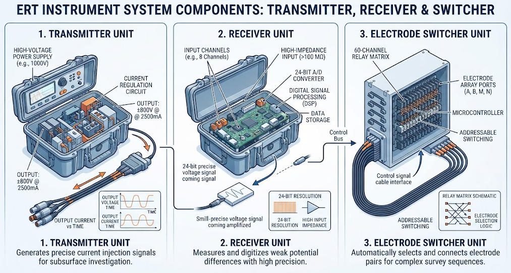
1.The Transmitter: Power Equals Depth
The transmitter pushes current into the ground. Ground resistance fights back. Wet clay may show 100 Ω·m. Dry sand may show 1,000 Ω·m. The transmitter must overcome this resistance.
Current output is the key metric. A 1 A transmitter handles most shallow surveys. A 5 A transmitter reaches 100 m in conductive ground. A 6 A transmitter with 1,100 V output penetrates 300 m or more.
Geotech’s WDF-5 power module delivers 800 V at 5 A. The WGMD-10X pushes 1,100 V at 6 A. This extra headroom matters in high-resistivity terrain. Without it, current cannot reach deep targets. The result is weak signals and poor inversion.
2.The Receiver: Precision Under Pressure
The receiver measures millivolt-level voltage differences. Deep targets produce tiny signals. Noise from power lines, radio towers, and natural fields competes with these signals.
Three specs define receiver quality:
A/D conversion bits: 16-bit receivers capture 65,536 voltage levels. 24-bit receivers capture 16,777,216 levels. The extra precision matters when signals are weak. A 24-bit unit resolves 0.1 μV. A 16-bit unit may miss the same signal entirely.
Input impedance: High input impedance prevents the receiver from drawing current. This protects measurement accuracy. Look for ≥50 MΩ. Lower impedance loads the ground circuit and distorts readings.
Dynamic range: This measures the ratio of the largest to smallest detectable signal. A 120 dB range handles both strong near-surface signals and weak deep signals. Narrow-range instruments clip strong signals or bury weak ones in noise.
Geotech’s WDAS-3 acquisition unit uses 24-bit A/D conversion. Input impedance exceeds 50 MΩ. These specs match or exceed industry leaders like ABEM and IRIS.
3.The Electrode Switcher: Speed and Scale
Manual switching kills productivity. Modern ERT instruments use relay-based switchers. They connect any electrode to current or potential circuits automatically.
Channel count determines survey speed. A 60-channel system collects data from 60 electrodes without moving cables. A 120-channel system covers twice the ground in the same time.
But more channels mean more cables. Weight adds up. A 120-electrode spread with 5 m spacing needs 600 m of cable. Vehicle-mounted reels become essential.
Geotech’s GIM-10 system supports 10-channel synchronous acquisition. The GIM-10 system handles 10 channels with bidirectional cascade. This means unlimited line extension without buying a massive central unit.
Ⅲ. ERT vs. Alternative Instruments
No single instrument solves every problem. The table below shows where ERT wins and where it loses.
| Parameter | ERT | GPR | Seismic |
|---|---|---|---|
| Depth range | 10 m–1 km | 0.1–30 m | 10 m–5 km |
| Resolution | 0.2–5 m | 0.01–1 m | 1–50 m |
| Best medium | All soils, especially conductive | Dry sand, resistive | All solid media |
| Cost per day | $500–2,000 | $300–1,500 | $2,000–10,000 |
| Data output | Quantitative resistivity | Qualitative reflections | Velocity models |
| Setup time | 1–4 hours | 0.5–1 hour | 4–8 hours |
ERT excels in conductive environments. Clay, saline water, and wet soils attenuate GPR signals. ERT thrives in these conditions. GPR wins in dry, resistive ground where centimeter resolution matters. Seismic reaches deeper but costs more and needs heavier equipment.
For landfill leakage, ERT maps contaminant plumes spatially. GPR pinpoints surface penetration points. The combination reduces remediation costs by 30% or more.
For landslide monitoring, ERT tracks groundwater fluctuations. Seismic surface waves assess rock shear strength. Together they predict failure risk better than either method alone.
Ⅳ. Survey Modes and Hardware Requirements
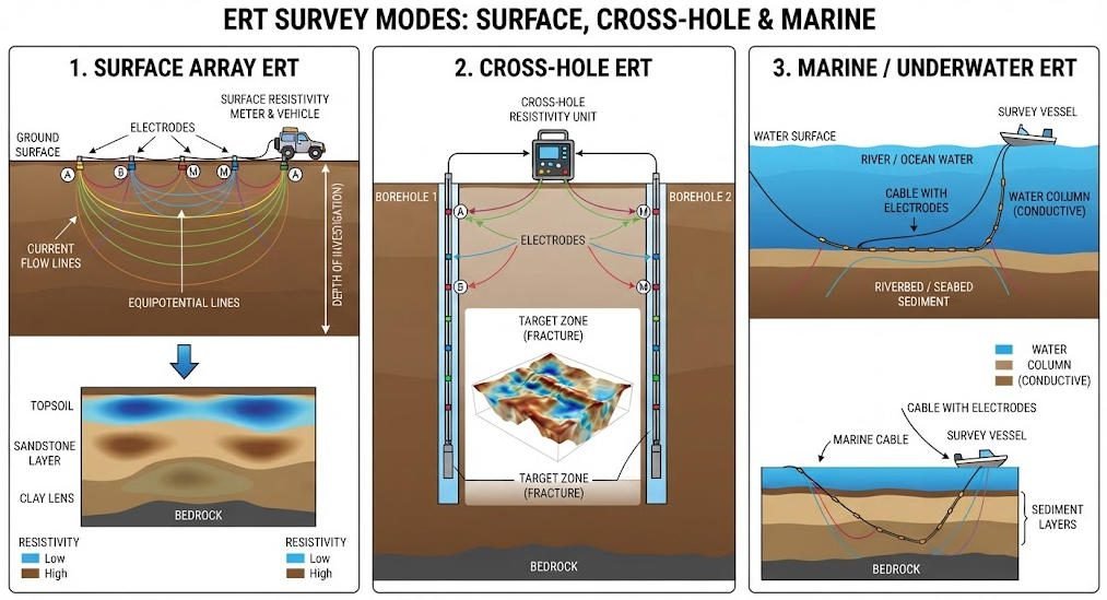
1.Surface ERT
Surface ERT is the default mode. Electrodes deploy in a line or grid. The instrument auto-switches pairs. This mode needs:
- Flat or gently sloping terrain (slope <15°)
- Good electrode contact (resistance <2 kΩ)
- Moderate transmitter power (1–5 A)
A California gold project used the WGMD-10X. Crews laid 1,200 electrodes across a slope. The 6 A transmitter penetrated 300 m. The 24-bit receiver captured weak deep signals. Inversion revealed an 800 m low-resistivity zone. Drilling verified gold vein thickness with <8% error.
2.Cross-Hole ERT
Cross-hole ERT places electrodes in boreholes. It overcomes surface obstacles. It reaches beneath buildings, roads, and steep terrain.
This mode demands non-polarizable electrodes. Ag/AgCl electrodes minimize electrochemical artifacts. Stainless steel electrodes polarize in IP mode. They distort chargeability measurements.
Cross-hole also needs higher transmitter voltage. Electrode spacing is smaller (1–5 m). Current must travel between holes, not just to the surface. A European landfill used cross-hole ERT with 0.3 m resolution. It mapped leakage pathways that surface arrays missed.
3.Underwater ERT
Underwater surveys map riverbeds and coastal zones. They need waterproof cables and connectors. IP68-rated cables resist saltwater corrosion.
Geotech’s marine-compatible systems use TPU-jacketed cables. They operate at 100 m depth. The WGMD-10X supports underwater and rolling measurement modes.
Ⅴ. Data Inversion: Software Is Half the Instrument
Hardware collects data. Software turns data into geology. Without good inversion, even perfect measurements are useless.
1.Algorithm Types
Smoothness-constrained inversion (Occam’s algorithm) produces gradual models. It avoids over-interpreting noise. It is ideal for layered geology and groundwater surveys. The downside: sharp boundaries appear blurred.
Structure-coupled inversion uses L1-norm regularization. It enhances edges. Cavities, faults, and layer contacts appear clearer. This suits karst and mining applications.
Joint inversion combines ERT with seismic or GPR data. Cross-gradient methods link electrical and elastic properties. Resolution improves by 35–40% over single-method inversion.
2.Software Compatibility
Your instrument must export to industry-standard formats. RES2DINV and RES3DINV are the most common. EarthImager, Aarhus Workbench, and PyGIMLi are also popular.
Geotech instruments export TXT and Excel formats. These import directly into RES2DINV. No format conversion is needed. This saves hours of preprocessing.
3.Processing Speed
2D inversion takes 5 minutes on a standard laptop. 3D inversion takes 2+ hours. GPU acceleration cuts this by 60%. AI-based CNN inversion reduces runtime by 70%. Geotech’s GIM Studio integrates these advances.
Ⅵ. Electrode Selection: The Forgotten Variable
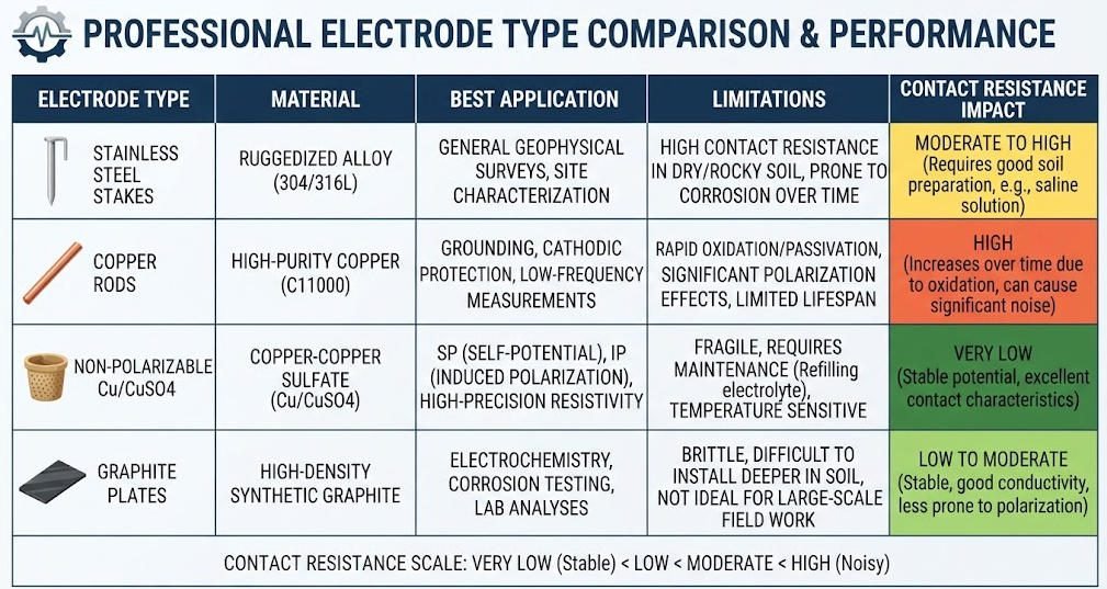
Electrodes seem simple. They are not. The wrong electrode ruins data quality.
| Electrode Type | Material | Best For | Limitations |
|---|---|---|---|
| Stainless steel | Steel alloy | General resistivity | Polarizes in IP mode |
| Copper | Pure Cu | Low-resistivity soils | Corrodes in saline ground |
| Ag/AgCl | Silver-silver chloride | IP and SP surveys | Higher cost, fragile |
| Plate | Steel sheet | Hard surfaces (concrete) | Poor contact, high resistance |
For standard resistivity surveys, stainless steel works. It is durable and cheap. For IP surveys, Ag/AgCl is essential. Polarization artifacts from steel electrodes can exceed 50%. This masks true chargeability signals.
Contact resistance is the hidden enemy. Parsekian et al. found that electrodes with 2.6 kΩ resistance produced 2–3× higher stacking errors than electrodes with 1.1 kΩ. The fix is simple: wet the ground, use bentonite gel, or drive electrodes deeper.
Ⅶ. Selecting the Right Geotech System
Match your project to the right hardware.
| Project Type | Depth | Key Spec | Recommended System |
|---|---|---|---|
| Groundwater exploration | 50–200 m | 5 A+ transmitter | WGMD-10X |
| Karst engineering | 10–50 m | 24-bit A/D, Wenner | GIM-5 |
| Mineral exploration (IP) | 100–500 m | IP mode, 6 A | GIM-10 |
| Environmental monitoring | 5–30 m | Time-lapse capable | WGMD-4 |
| Cross-hole tunnel survey | 20–100 m | Ag/AgCl electrodes | GIM-10 + cross-hole kit |
| Underwater coastal | 0–50 m | IP68 cables | WGMD-10X marine |
The GIM Series integrates resistivity, IP, and SP in one unit. Its 24-bit A/D conversion achieves 0.3% accuracy. The IP67 housing and -20°C to +60°C operating range handle extreme environments. Bidirectional cascade technology breaks the 1,500 m depth barrier.

Related Articles
Explore related Geotech resources for your geophysical projects:
- What Is Electrical Resistivity Tomography? Complete ERT Guide
- ERT Instruments: A Comprehensive Guide
- Underground Electrical Exploration Methods Compared
- Comparative Study: HDR, DC Sounding & ERT
- ERT vs TEM: Which Geophysical Method Fits Your Project?
- Induced Polarization Method for Mineral Exploration
- Geophysical Exploration Classification & Applications
- WGMD-10X Multi-Channel High-Density System
Reference Sources
| Authority | Source URL |
|---|---|
| U.S. Environmental Protection Agency (EPA) — Electrical Resistivity | https://www.epa.gov/environmental-geophysics/electrical-resistivity |
| Parsekian et al. — Comparing ERT Instruments (Colorado School of Mines) | https://people.mines.edu/ksingha/wp-content/uploads/sites/44/2018/12/parsekian_etal2017.pdf |
| Society of Exploration Geophysicists (SEG) | https://seg.org/ |
| CLU-IN — Electrical Resistivity Tomography Technology Overview | https://clu-in.org/characterization/technologies/default2.focus/sec/Geophysical_Methods/cat/Electrical_Resistivity_Tomography/ |
| Geotech Instrument Co., Ltd. — ERT Instruments Guide | https://geotechcn.net/service/ert-instruments/ |
FAQ
Q1: What is the difference between 16-bit and 24-bit A/D conversion in ERT instruments?
A: A/D conversion bits determine voltage measurement precision. 16-bit converters resolve 65,536 levels. 24-bit converters resolve 16,777,216 levels. For deep targets with weak signals, 24-bit instruments capture data that 16-bit units miss. Geotech’s GIM Series uses 24-bit A/D conversion for 0.1 μV resolution.
Q2: How many channels do I need for my ERT survey?
A: Channel count determines survey speed. A 60-channel system covers large spreads faster than 24-channel units. For linear projects like roads, 60 channels suffice. For 3D grids or time-lapse monitoring, 120+ channels reduce field time. Geotech’s bidirectional cascade technology lets you start small and expand later.
Q3: Why does transmitter current matter more than voltage for deep surveys?
A: Current determines how much charge flows through the ground. High-resistivity terrain resists current flow. A 1 A transmitter may fail where a 5 A transmitter succeeds. Voltage helps overcome ground resistance, but current is what reaches the target. For depths beyond 100 m, choose transmitters rated at 3 A or higher.
Q4: Can I use stainless steel electrodes for IP surveys?
A: No. Stainless steel electrodes polarize when current flows. This creates artificial chargeability signals that mask true geology. IP surveys require non-polarizable Ag/AgCl electrodes. For resistivity-only surveys, stainless steel is fine and more durable.
Q5: How do I verify that my ERT instrument produces reliable data?
A: Run three checks before each survey. First, measure contact resistance at every electrode. Values above 2 kΩ need treatment. Second, collect reciprocal measurements. Swapping current and potential electrodes should produce identical apparent resistivity. Third, review stacking errors. Errors above 5% indicate noise or poor contact.