Welcome to Geotech!


Electrical Resistivity and Induced Polarization: Methods, Equipment Selection
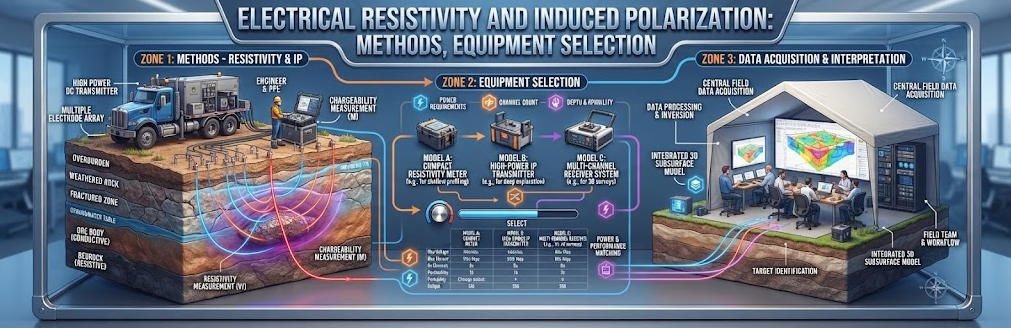
Overview:Electrical Resistivity and Induced Polarization are core active electrical geophysical techniques for subsurface characterization. This guide explains Electrical Resistivity survey principles and evaluates how Induced Polarization data reduces interpretive ambiguity across geotechnical and exploration Electrical Resistivity product applications.
Ⅰ. What Is Electrical Resistivity?
1. Definition of Electrical Resistivity
Electrical resistivity is a measure of how strongly a material opposes the flow of electrical current. In geophysics, electrical resistivity surveys inject current into the ground and measure voltage differences to estimate subsurface electrical properties.
Resistivity is expressed in ohm-meters (Ω·m). It depends on the properties of the material, including mineral composition, pore structure, fluid content, and the electrical conductivity of pore fluids.
Electrical resistivity methods help identify contrasts between geological materials. However, resistivity alone rarely identifies a specific rock type or contaminant with certainty.
2. Electrical Resistivity in Geological Materials
Electrical current travels through geological materials through different conduction mechanisms.
In many soils and rocks, ionic conduction through pore fluids plays a major role. Clay minerals can also influence electrical conduction through surface-related processes. Metallic minerals may support electronic conduction and contribute to polarization effects.
The measured resistivity therefore reflects several interacting properties:
- Pore-fluid salinity and conductivity.
- Water saturation and pore connectivity.
- Porosity and fracture distribution.
- Clay content and mineral surface properties.
- Temperature and geological structure.
These factors can produce overlapping resistivity values in different materials. Interpretation requires geological context and, where available, borehole or laboratory information.
3. Resistivity and Conductivity
Resistivity and conductivity describe the same electrical property from opposite perspectives.
σ=ρ1
Where:
- σ is electrical conductivity, expressed in siemens per meter (S/m).
- ρ is electrical resistivity, expressed in ohm-meters (Ω·m).
A low-resistivity material has relatively high conductivity, while a high-resistivity material has relatively low conductivity.
This relationship is useful when comparing resistivity surveys with electromagnetic methods, which often respond to electrical conductivity.
Ⅱ. What Is Surface Resistivity?
1. Definition and Geophysical Meaning
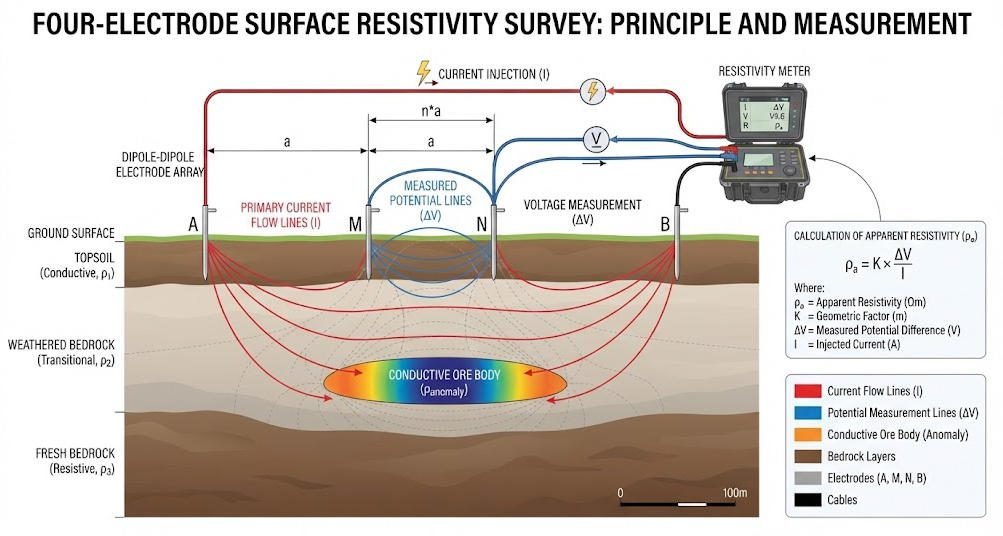
Surface resistivity surveying is a near-surface geophysical approach that uses electrodes placed on the ground to measure electrical responses and estimate subsurface resistivity.
In this article, Surface Resistivity refers to surface-based geophysical resistivity surveys. It does not refer to the surface electrical resistance of a manufactured material, coating, or insulating specimen.
A surface survey typically uses current electrodes to inject current and potential electrodes to measure voltage differences. The electrode arrangement determines the geometric factor used to calculate apparent resistivity.
2. How Surface Resistivity Measurements Work
A conventional four-electrode survey uses two current electrodes and two potential electrodes.
The process is straightforward:
- Install electrodes at predetermined surface locations.
- Inject a controlled current through the current electrodes.
- Measure the potential difference between the potential electrodes.
- Record the current, voltage, and electrode geometry.
- Calculate apparent resistivity using the appropriate geometric factor.
- Repeat the measurement using different electrode positions or spacings.
The resulting dataset represents the electrical response of a volume of ground, not a single point or isolated layer.
3. Surface Resistivity Versus Material Surface Resistivity
The term surface resistivity can also appear in electrical-material testing. In that context, it may refer to electrical properties measured along or across the surface of a material under a prescribed test procedure.
The distinction matters for search intent and technical accuracy.
| Term | Meaning | Typical Application |
|---|---|---|
| Surface-based geophysical resistivity | Electrical resistivity estimated from surface electrode measurements | Groundwater, environmental, and engineering surveys |
| Material surface resistivity | Electrical resistance-related property of a material surface | Insulation, coatings, and materials testing |
| Electrical resistivity | Intrinsic electrical property of a material | Geophysics and material characterization |
| Apparent resistivity | Field-derived value based on measured voltage, current, and geometry | Resistivity surveying and inversion |
When using the keyword Surface Resistivity for geophysical content, the page should explicitly establish the ground-survey context.
Ⅲ. What Is Induced Polarization?
1. Definition of Induced Polarization
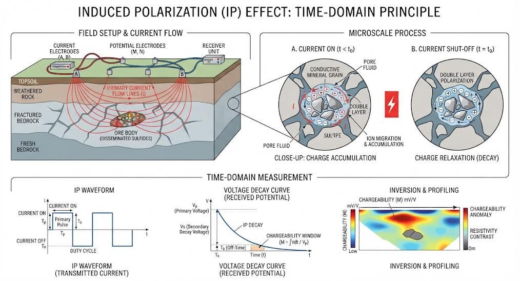
Induced Polarization (IP) is an active geophysical method that measures the delayed or frequency-dependent electrical response of subsurface materials after an electrical field is applied.
The method is sensitive to polarization processes at mineral-fluid interfaces and other electrical boundaries. It can provide information that complements resistivity measurements.
The U.S. Environmental Protection Agency explains that IP responses arise from electrical charge storage and release within earth materials. The method can be measured in the time domain or frequency domain.
2. Physical Mechanisms of IP
When current flows through the ground, electrical charges may accumulate at interfaces between minerals and pore fluids.
After the applied current changes or stops, the electrical response may not disappear immediately. The remaining response can decay over time or vary with the frequency of the applied signal.
Two broad mechanisms are commonly discussed:
- Electrode polarization: Charge accumulation at interfaces involving conductive mineral grains and pore fluids.
- Membrane polarization: Charge separation associated with restricted ionic movement in fine pores or clay-rich materials.
The relative contribution of these mechanisms depends on the geological environment and the physical properties of the materials.
3. Time-Domain and Frequency-Domain IP
Time-domain IP measures the decay of voltage after the transmitter current is switched off.
Frequency-domain IP measures changes in amplitude and phase between the injected current and the measured voltage response at selected frequencies.
Spectral induced polarization (SIP), also called complex resistivity in relevant contexts, examines electrical response across multiple frequencies. It can help characterize frequency-dependent polarization behavior.
Ⅳ. Electrical Resistivity Methods
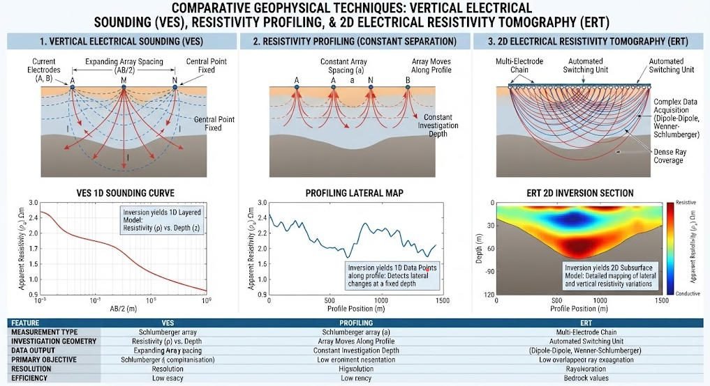
Electrical resistivity methods differ in electrode geometry, measurement coverage, and the way they represent the subsurface.
The main approaches include vertical electrical sounding, resistivity profiling, and electrical resistivity tomography.
1. Vertical Electrical Sounding (VES)
VES investigates changes in apparent resistivity with increasing electrode spacing around a fixed survey center.
As the electrode spacing increases, the measurement becomes sensitive to a different and generally larger subsurface volume. The response is then interpreted using a layered-earth model or another suitable inversion approach.
VES is useful when the survey objective emphasizes vertical variation beneath a relatively fixed location.
However, lateral geological changes can distort a one-dimensional interpretation. Survey design should account for possible lateral heterogeneity.
2. Resistivity Profiling
Resistivity profiling measures lateral variations in electrical properties along a survey line.
The electrode arrangement is moved or repeated along the profile, allowing the survey team to map changes in apparent resistivity.
Profiling can be useful for reconnaissance surveys and for locating lateral electrical contrasts. It does not automatically provide a fully resolved depth model.
3. Electrical Resistivity Tomography (ERT)
ERT collects multiple resistivity measurements using a multi-electrode array. The measurements are combined through inversion to estimate the spatial distribution of subsurface resistivity.
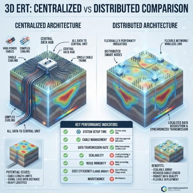
A 2D ERT survey typically uses electrodes along a line and produces a resistivity cross-section. A 3D survey uses a suitable three-dimensional electrode layout or an appropriately designed set of survey lines.
The final model depends on the measurement geometry, data quality, inversion settings, and geological assumptions.
4. Comparison of Electrical Resistivity Methods
| Method | Main Survey Geometry | Primary Output | Typical Use |
|---|---|---|---|
| VES | Expanding electrode spacing around a fixed center | 1D resistivity-depth interpretation | Layered ground and vertical electrical changes |
| Profiling | Repeated measurements along a line | Lateral apparent-resistivity variation | Reconnaissance and lateral anomaly mapping |
| 2D ERT | Multi-electrode line | Resistivity cross-section | Geological boundaries, weathered zones, and site characterization |
| 3D ERT | Grid or 3D electrode configuration | 3D resistivity model | Complex targets requiring spatial coverage |
| Time-lapse ERT | Repeated or automated measurements | Changes in resistivity over time | Seepage, infiltration, and environmental monitoring |
Ⅴ. Apparent Resistivity, Data Processing, and Inversion
1. What Is Apparent Resistivity?
Apparent resistivity is the value that a homogeneous reference earth model would produce for a given electrode configuration and measured voltage-to-current ratio.
It is not necessarily the true resistivity of any individual geological layer.
For a general four-electrode configuration:
ρa=KIΔV
Where:
- ρa is apparent resistivity.
- K is the geometric factor.
- ΔV is the measured potential difference.
- I is the injected current.
The geometric factor depends on electrode positions and the assumed measurement geometry. The U.S. EPA describes apparent resistivity as a geometry-dependent field value and explains how electrode arrays influence investigation depth.
2. Why Is Inversion Necessary?
Inversion estimates a subsurface resistivity model that can reproduce the observed field measurements within an acceptable level of misfit.
The process generally includes:
- Preparing the measured data and electrode geometry.
- Identifying erroneous or low-quality measurements.
- Selecting a suitable forward model and inversion approach.
- Estimating a resistivity distribution.
- Reviewing data fit, model stability, and sensitivity.
- Interpreting the model with geological information.
Different models may explain the same field data. Therefore, inversion results should be treated as constrained interpretations rather than unique representations of the ground.
3. Factors That Affect Inversion Reliability
The reliability of an inversion depends on:
- Electrode spacing and survey coverage.
- Measurement noise and contact quality.
- Current and voltage accuracy.
- Geological complexity.
- Model parameterization and regularization.
- Data errors and missing measurements.
- The depth and resolution supported by the survey geometry.
A visually smooth model does not automatically imply high geological certainty.
Ⅵ. Electrical Resistivity and IP: Complementary Methods

1. Why Combine Resistivity and IP?
Electrical resistivity and IP measure different aspects of the subsurface electrical response.
Resistivity primarily reflects how easily current flows through the ground. IP measures polarization-related behavior, such as delayed voltage decay or frequency-dependent phase response.
Combining the two datasets may reduce some interpretation ambiguity, especially where different materials have overlapping resistivity values but different polarization responses.
However, IP does not uniquely identify a mineral, contaminant, or geological unit. Its interpretation also depends on geological conditions and data quality.
2. Resistivity and IP Comparison
| Parameter | Electrical Resistivity | Induced Polarization |
|---|---|---|
| Physical response | Electrical conduction | Electrical polarization |
| Typical measurement | Voltage and injected current | Voltage decay, chargeability, or phase |
| Main output | Apparent resistivity and resistivity model | Chargeability or frequency-dependent response |
| Sensitivity | Pore-fluid conductivity, saturation, porosity, mineralogy | Grain-fluid interfaces, conductive minerals, surface properties |
| Common role | Mapping electrical contrasts | Adding polarization-related information |
| Main limitation | Non-unique relationship between resistivity and geology | Non-unique polarization response and demanding data quality |
3. Integrated Interpretation
A practical integrated workflow may include:
- Reviewing resistivity anomalies and their spatial geometry.
- Examining chargeability or phase responses.
- Comparing the spatial relationships between the datasets.
- Considering lithology, groundwater conditions, and mineralogical evidence.
- Evaluating whether additional geological or geochemical data are needed.
The strongest interpretation is not necessarily the one with the most dramatic anomaly. It is the one that is consistent with the measured data and independent geological evidence.
Ⅶ. Applications of Electrical Resistivity and Induced Polarization
1. Mineral Exploration
Resistivity and IP are commonly used in mineral exploration to investigate electrical contrasts associated with geological structures and mineralization.
IP can be useful for targets with measurable polarization responses, including some disseminated sulfide systems. Resistivity provides complementary information about conductive and resistive zones.
The response of a target depends on mineralogy, grain distribution, alteration, pore fluids, and geological structure. An IP anomaly alone does not confirm an economic mineral deposit.
2. Groundwater Exploration
Electrical resistivity surveys can help map weathered zones, fractures, sedimentary layers, and electrical contrasts associated with groundwater conditions.
Low resistivity may be associated with saline water or clay-rich materials, while higher resistivity may occur in dry or less conductive formations. These relationships are site-dependent.
IP may provide additional information where the polarization properties of the materials are relevant.
3. Environmental Investigation
Electrical resistivity and IP can support investigations of landfill boundaries, seepage pathways, subsurface heterogeneity, and changes associated with fluid movement.
Electrical anomalies may reflect variations in moisture, salinity, clay content, or other material properties. They should not be interpreted as direct chemical identification of contaminants.
Time-lapse resistivity surveys can help monitor changes in subsurface electrical conditions when measurements are repeated with consistent survey geometry.
4. Engineering and Geotechnical Investigation
ERT can help characterize weathered rock, fractured zones, and subsurface boundaries relevant to engineering site investigations.
Depending on geological conditions, resistivity contrasts may also help identify areas requiring further investigation for possible cavities or disturbed ground.
IP can provide complementary information where polarization differences are measurable.
Geophysical results should be integrated with boreholes, geological mapping, and other engineering investigation methods.
Ⅷ. Electrode Arrays and Survey Design
1. Common Electrode Arrays
The electrode array affects signal strength, sensitivity patterns, investigation depth, and lateral resolution.
Common configurations include Wenner, Schlumberger, dipole-dipole, and gradient arrays.
| Array | General Characteristics | Considerations |
|---|---|---|
| Wenner | Equal electrode spacing; often produces relatively strong voltage signals | Useful for lateral changes and some noisy environments |
| Schlumberger | Potential electrodes remain relatively close while current electrodes expand | Often practical for sounding and vertical variation |
| Dipole-dipole | Uses current and potential dipoles separated by a selected factor | Sensitive to lateral changes but can produce weaker signals |
| Gradient | Uses a broad current-electrode separation with multiple potential measurements | Can provide efficient coverage for suitable survey layouts |
Array performance depends on the site, target geometry, noise conditions, and acquisition system. No single array is universally optimal. ASTM D6431 discusses common DC resistivity survey arrangements and field considerations.
2. Electrode Spacing and Investigation Depth
Increasing electrode spacing generally increases the subsurface volume influencing the measurement. However, investigation depth is not determined by spacing alone.
Depth sensitivity depends on array geometry, resistivity structure, signal quality, and the sensitivity of the inversion model.
The effective depth of investigation should be evaluated from the survey design and data sensitivity rather than inferred from a fixed universal ratio.
3. Survey Resolution and Coverage
Smaller electrode spacing can improve the ability to sample near-surface lateral variations. It also increases the number of measurements required for a given survey length.
Larger spacing can extend the sensitivity to broader and deeper volumes but may reduce the detail available for small targets.
Survey design should balance target size, depth, expected contrast, field access, noise, and acquisition time.
Ⅸ. Electrical Resistivity Product: Equipment Selection Guide
1. What Is an Electrical Resistivity Product?
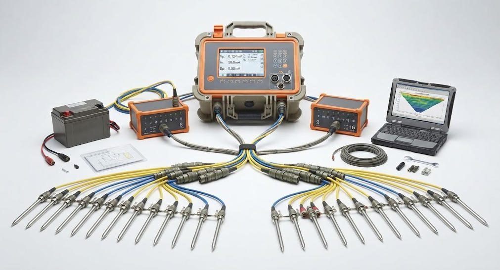
An Electrical Resistivity Product is a geophysical instrument or system designed to inject current, measure electrical potential differences, or acquire and process resistivity data.
A complete system may include a resistivity meter, current transmitter, receiver or voltage-measurement unit, electrode array, cables, switching equipment, positioning tools, and processing software.
The appropriate configuration depends on the survey method, target depth, required data coverage, and field conditions.
2. Main Equipment Components
| Component | Function | Selection Considerations |
|---|---|---|
| Resistivity meter or receiver | Measures voltage and records data | Measurement range, stability, resolution, noise |
| Current transmitter | Injects controlled current | Output capability, waveform, duty cycle, safety |
| Electrodes | Establish electrical contact with the ground | Material, dimensions, contact conditions |
| Cables and connectors | Connect electrodes and equipment | Length, insulation, durability, leakage |
| Electrode switching unit | Automates electrode combinations | Channel capacity, switching reliability |
| Acquisition software | Controls measurements and stores data | Survey programming, data export, metadata |
| Processing and inversion software | Converts field data into models | Array support, inversion options, quality control |
3. Technical Specifications to Evaluate
Before purchasing an electrical resistivity product, verify:
- Current output and operating modes.
- Voltage measurement range and resolution.
- Measurement accuracy and stability.
- Input impedance and noise performance.
- Electrode switching and channel capacity.
- Supported arrays and survey modes.
- Data storage and export formats.
- Software compatibility.
- Environmental protection and operating temperature.
- Calibration, training, and service support.
Specifications should be assessed against the actual survey requirements. A higher current rating or greater channel count does not automatically guarantee better data quality.
4. Selecting Equipment for Different Projects
| Project Type | Equipment Priorities | Key Questions |
|---|---|---|
| Groundwater investigation | Stable resistivity measurements and suitable arrays | What geological contrast is expected? |
| Mineral exploration | Resistivity and compatible IP capability | Is chargeability measurement required? |
| Environmental monitoring | Repeatable measurements and time-lapse support | Can electrode geometry remain consistent? |
| Engineering survey | Suitable resolution and field deployment | What target size and depth must be resolved? |
| Large ERT project | Multi-electrode switching and efficient acquisition | What coverage and channel capacity are needed? |
| 3D investigation | 3D layout support and processing compatibility | Is the proposed electrode geometry adequate? |
Ⅹ. Field Procedures, Quality Control, and Troubleshooting
1. Pre-Survey Planning
Before field deployment, define the target, expected electrical contrast, survey geometry, electrode spacing, and data-quality requirements.
Review access, surface conditions, potential interference sources, and the suitability of the selected array.
Prepare the acquisition system, cables, electrodes, and positioning records.
2. Electrode Installation and Contact Quality
Install electrodes according to the planned geometry.
Poor electrode contact can reduce current injection, increase noise, and destabilize voltage measurements. On hard, dry, frozen, or rocky surfaces, electrode installation may require additional preparation or alternative contact arrangements.
Record unusual contact conditions and follow appropriate site and equipment safety procedures.
3. Data Acquisition and Quality Control
During acquisition, monitor:
- Injected current and measured voltage.
- Electrode contact quality.
- Noise and unstable readings.
- Repeated measurements.
- Electrode positions and array geometry.
- Instrument warnings and channel status.
For IP surveys, also inspect decay-curve behavior or frequency-domain signal quality where supported.
4. Common Field Problems
| Problem | Possible Cause | Recommended Action |
|---|---|---|
| Low measured voltage | Weak signal, poor contact, or array geometry | Check contact and measurement configuration |
| Unstable readings | Electrical noise or changing contact | Inspect cables, electrodes, and interference sources |
| Low injected current | High contact resistance or transmitter limitations | Review contact conditions and system settings |
| Inconsistent repeat readings | Changing ground contact or environmental conditions | Repeat measurements and document changes |
| Unexpected anomalies | Geological variation, data errors, or interference | Review raw data and compare with independent evidence |
| Poor inversion fit | Data quality, model mismatch, or unsuitable parameters | Inspect outliers, geometry, and inversion assumptions |
Ⅺ. Limitations and Interpretation Risks
Electrical resistivity and IP are indirect geophysical methods. Their results describe electrical responses, not geological materials directly.
1. Non-Uniqueness
Different combinations of lithology, pore-fluid chemistry, saturation, porosity, and mineral content can produce similar electrical responses.
Geological interpretation should therefore use independent evidence whenever possible.
2. Depth and Resolution Limitations
A survey cannot resolve every target at every depth. Resolution depends on electrode spacing, array geometry, data quality, target dimensions, and inversion sensitivity.
A model may show a feature that is poorly constrained by the measurements. Interpretation should consider data sensitivity and uncertainty.
3. Environmental and Cultural Noise
Power lines, buried infrastructure, fences, metallic structures, and other electrical sources may interfere with measurements.
Survey planning should identify potential noise sources and account for them in array selection and field procedures.
4. Surface Conditions
Hard rock, dry soil, frozen ground, and highly resistive surface layers can make electrode contact difficult.
Alternative electrode arrangements or complementary methods may be appropriate when galvanic contact is impractical.
Ⅻ. Geotech Equipment and Related Technical Resources
Geotech’s electrical exploration equipment portfolio includes systems associated with resistivity and induced polarization applications.
When evaluating a specific system, confirm its supported survey methods, transmitter and receiver configuration, electrode switching, data acquisition software, and technical specifications against the latest official product documentation.
Related Geotech resources:
- High Power IP System
- High Power IP System — Related Configuration
- WDA-1 DC Meter
- WGMD-9 Distributed System
- What Are Resistivity Meters?
- Electrical Imaging: ERT and VES
- Induced Polarization Method Guide
ⅩⅢ. Conclusion
Electrical resistivity methods provide information about the electrical properties of subsurface materials. Surface-based surveys use electrode arrays to measure voltage responses and calculate apparent resistivity.
Induced Polarization adds information about polarization-related behavior, such as chargeability and frequency-dependent response. Combining resistivity and IP can support more informed interpretation, but neither method uniquely identifies geological materials.
A reliable project requires appropriate survey design, compatible equipment, careful field procedures, data-quality control, and geological validation.
When selecting an Electrical Resistivity Product, prioritize the project’s measurement objectives, electrode configuration, signal quality, software compatibility, and field conditions rather than relying on isolated specifications.
Related Articles
| Title | Core Content | URL |
|---|---|---|
| High Power IP System | Equipment system for high-power induced polarization and electrical exploration applications | https://geotechcn.net/products/electrical-instrument/high-power-ip-system/ |
| High Power IP System — Related Configuration | Related electrical exploration system configuration | https://geotechcn.net/products/electrical-instrument/high-power-ip-system-2/ |
| WDA-1 DC Meter | DC electrical measurement equipment and resistivity-related applications | https://geotechcn.net/products/electrical-instrument/wda-1-dc-meter/ |
| WGMD-9 Distributed System | Distributed electrical exploration system | https://geotechcn.net/products/electrical-instrument/wgmd-9-distributed-system/ |
| What Are Resistivity Meters? | Resistivity measurement principles, equipment functions, and applications | https://geotechcn.net/service/what-are-resistivity-meters/ |
| Electrical Imaging: ERT and VES | Electrical resistivity imaging, sounding, and survey methods | https://geotechcn.net/service/electrical-imaging-ert-ves/ |
| Induced Polarization Method Guide | IP principles, measurement methods, and applications | https://geotechcn.net/service/induced-polarization-ip/ |
| Geophysical Surveying Explained | Overview of geophysical methods and subsurface investigation | https://geotechcn.net/service/geophysical-surveying-explained/ |
| Geophysical Methods Demystified | Overview of geophysical exploration methods and their applications | https://geotechcn.net/service/geophysical-methods-demystified/ |
Reference Sources
| Title | Core Content | URL |
|---|---|---|
| Electrical Resistivity — U.S. Environmental Protection Agency | Apparent resistivity, electrode arrays, geometric factors, and depth of investigation | https://www.epa.gov/environmental-geophysics/electrical-resistivity |
| Induced Polarization (IP) and Complex Resistivity — U.S. Environmental Protection Agency | IP physical principles, time-domain and frequency-domain measurements, and applications | https://www.epa.gov/environmental-geophysics/induced-polarization-ip-and-complex-resistivity |
| Electrical Methods — U.S. Environmental Protection Agency | Overview of electrical geophysical methods and subsurface electrical properties | https://www.epa.gov/environmental-geophysics/electrical-methods |
| ASTM D6431-25 — Standard Guide for Using the Direct Current Resistivity Method for Geophysical Site Investigation | DC resistivity survey design, electrode arrays, field procedures, and interpretation considerations | https://store.astm.org/d6431-25.html |
| ASTM International | Standards and technical guidance for geophysical investigation and measurement practices | https://www.astm.or |
FAQ
Q1. What is electrical resistivity in geophysics?
Electrical resistivity measures how strongly subsurface materials oppose electrical current. Geophysicists inject current through electrodes and measure voltage differences to calculate apparent resistivity. The results help identify electrical contrasts associated with lithology, groundwater conditions, and geological structures, but interpretation requires geological context because different materials can share similar resistivity values.
Q2. What is the difference between electrical resistivity and induced polarization?
Electrical resistivity measures the ground’s response to electrical current, while induced polarization measures delayed or frequency-dependent electrical behavior. Resistivity helps map conductive and resistive zones. IP adds information about chargeability or phase response. Combining both methods can improve geological interpretation, although neither method uniquely identifies a particular mineral or subsurface material.
Q3. What is surface resistivity surveying used for?
Surface resistivity surveying uses electrodes placed on the ground to investigate subsurface electrical properties. It is commonly used in groundwater exploration, environmental assessment, and engineering investigations. By changing electrode spacing and arrangement, survey teams can collect data sensitive to different subsurface volumes and use appropriate processing methods to estimate resistivity distributions.
Q4. What are the main electrical resistivity methods?
The main methods include vertical electrical sounding (VES), resistivity profiling, and electrical resistivity tomography (ERT). VES emphasizes vertical electrical variation, profiling maps lateral changes, and ERT combines multiple measurements to estimate a two-dimensional or three-dimensional resistivity model. The suitable method depends on the target geometry, depth, resolution, and site conditions.
Q5. How do I choose an electrical resistivity product?
Choose an electrical resistivity product based on the survey objective, target depth, electrode configuration, measurement range, noise performance, and software compatibility. Projects requiring induced polarization must also verify IP measurement capabilities and transmitter compatibility. Evaluate field conditions, maintenance, training, and service support alongside technical specifications to ensure the system fits the actual workflow.