Welcome to Geotech!



GEO-G1 Remote Resistivity & IP System Review:4G-Monitored ERT Instruments
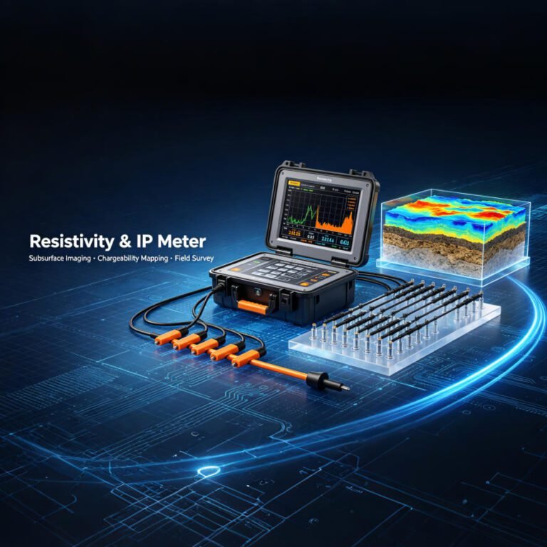
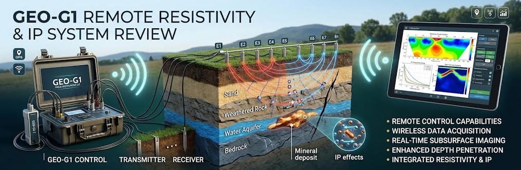
Overview:The GEO-G1 is a remote electrical resistivity tomography and induced polarization system built around 32-bit acquisition, cascaded electrode converters, and 4G monitoring. This electrical resistivity tomography review explains how induced polarization data, segmented surveys, and rolling layouts cut field time for engineering, mining, and environmental teams.
Ⅰ. What Is the GEO-G1 Remote Resistivity & IP System?
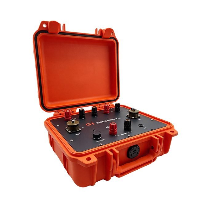
Direct answer: The GEO-G1 is a remote-controlled electrical resistivity tomography (ERT) and time-domain induced polarization (TDIP) system that pairs a 32-bit receiver with cascaded electrode converters and Bluetooth/4G telemetry.
ERT works by injecting DC current through two electrodes (A, B) and measuring the potential difference between two others (M, N). The instrument calculates apparent resistivity as ρa = K·ΔV/I, where K is the array geometric factor. Inversion software then converts thousands of these quadrupole readings into 2D or 3D resistivity sections. State geological surveys describe resistivity mapping and IP as core electrical methods for aquifer framing and mineral exploration.
TDIP adds a second parameter. After current shut-off, the receiver records the slowly decaying secondary voltage and integrates it into chargeability M. This parameter is critical in mineral work because sulfide ores commonly show 10–50% polarizability against roughly 2% for typical host rocks.
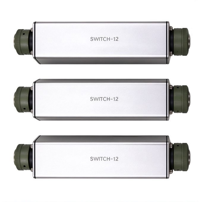
Ⅱ. System Architecture and the 120-Channel Configuration
1. Non-Directional Cascaded Converters
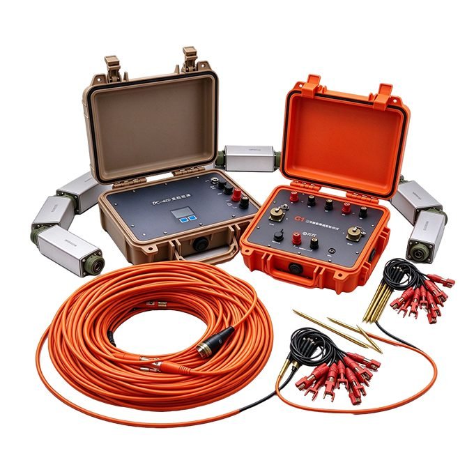
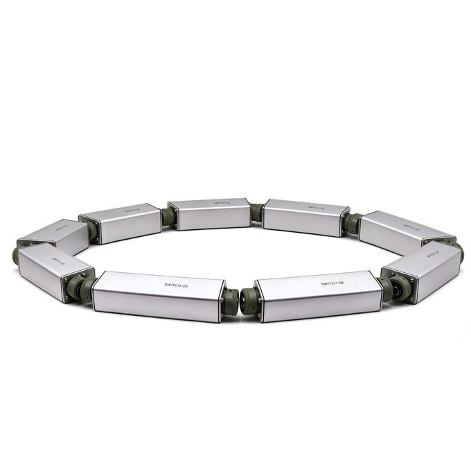
Each Switch-12 converter serves 12 electrodes and weighs only 0.5 kg. Units cascade without directional limits and carry 1000 V / 4 A. Crews can reel cable in or out during measurement, so the array never locks the crew into one geometry.
2. Smart Segmented Survey
The GEO-G1 starts measuring with only part of the electrode line deployed. This matters on long profiles and in difficult terrain. Field teams acquire the active segment, then leapfrog converters forward.
3. Dual-Mode Wireless Control
Bluetooth handles short-range configuration. A built-in 4G module enables remote operation and real-time data monitoring. The practical benefit is fewer people on the line, although 4G telemetry depends on cellular coverage at the site.
4. Power Chain and Endurance
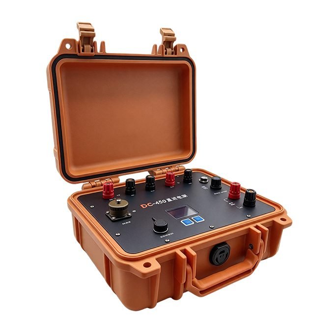
The DC-480 external supply delivers up to 480 V in 10 steps at a maximum of 2.0 A. Inside the main unit, a 12 V / 7 Ah lithium battery supports 40+ hours of continuous operation without 4G. Actual endurance depends on duty cycle and temperature.
| Item | Component | Key Rating | Function |
| 1 | GEO-G1 main unit | 32-bit ADC, Bluetooth + 4G | Acquisition and remote control |
| 2 | DC-480 power supply | 480 V, 10 steps, 2.0 A, IP67 | Adjustable transmitting source |
| 3 | Switch-12 converter ×10 | 12 electrodes, 1000 V/4 A, 0.5 kg | Electrode switching |
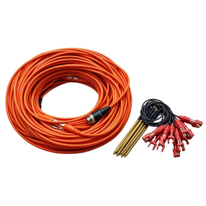
| 4 | Cascaded cable ×10 | 5 / 10 m interval, 12 taps | Signal routing |
Ⅲ. Acquisition Performance and Noise Immunity
1. Receiver Chain
The receiver uses a 32-bit ADC with 2 nV voltage resolution and ±0.1% ±1 digit accuracy. Input impedance is ≥50 MΩ, which limits loading errors on high-resistivity ground. Chargeability accuracy is specified at ±0.2%.
2. Transmitter Chain
The transmitter covers ±8 A with 2.5 nA current resolution and a 1200 V maximum. Pulse width and duty cycle are adjustable. One note for buyers: the brochure highlights state “up to 1500 V / 6 A,” while the specification table lists 1200 V / 8 A. Confirm the final transmitter configuration with the manufacturer before procurement.
3. Anti-Interference Design
Power-line rejection reaches 140 dB. Self-potential compensation covers ±10 V. These figures help near pipelines, railways, and power corridors, but real-world performance still depends on grounding quality and array choice.
| Parameter | Receiver | Transmitter |
| Range | ±12 V voltage | ±8 A current, 1200 V max |
| Accuracy | ±0.1% ±1 digit | ±0.1% |
| ADC / resolution | 32-bit, 2 nV | 2.5 nA current resolution |
| Input impedance | ≥50 MΩ | — |
| Chargeability accuracy | ±0.2% | — |
| SP compensation | ±10 V | — |
| Power-line rejection | 140 dB | — |
| Pulse control | — | Adjustable width and duty cycle |
Ⅳ. Survey Design: From 2D Profiles to 3D Arrays
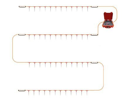
1. 2D Rolling Layout
For a single profile, converters cascade along the line while the main unit sits at one end. The crew measures the first segment, then rolls the trailing converters forward. Data density stays uniform without re-staking the full line.


2. 3D Multi-Line Cascading
Parallel lines repeat the same pattern. A single main unit can control multiple cascaded lines remotely. This produces volumetric models for complex geology such as karst or tailings systems.
3. Array Selection
Array choice controls depth sensitivity and signal level. Wenner and Schlumberger arrays are common for imaging because they respond well to vertical changes. Dipole-dipole gives better lateral resolution but weaker signal. Typical electrode spacing is 5 or 10 m, depending on target scale.
| Array | Best for | Signal strength | Horizontal resolution | Noise tolerance |
| Wenner | Vertical layering, VES-style depth | High | Moderate | High |
| Schlumberger | Deep sounding with fewer electrodes | High | Moderate | High |
| Dipole-dipole | Lateral structures, 3D coverage | Low | High | Low |
Ⅴ. Field Applications
1. Remote and Long-Term Monitoring
The 4G link suits dams, tailings ponds, and landslide sites. Crews can schedule repeat surveys without re-entering the area. Time-lapse sections then track resistivity change over seasons.
2. Tailings Dam Seepage Detection
In the manufacturer’s example, low-resistivity anomalies highlighted leakage pathways beneath a tailings dam. Depending on pore-fluid chemistry and clay content, seepage zones often contrast sharply with dry embankment material.
3. Lithology, Groundwater, and Karst
ERT maps aquifers, fracture zones, and bedrock relief. US EPA lists groundwater prospecting, contamination studies, karst void detection, and mineral exploration as proven resistivity applications.
4. Urban, Environmental, and Disaster-Prevention Work
Engineering crews use ERT for cavity detection and foundation studies. Archaeology and urban surveys benefit from rolling layouts where access is limited. In each case, correlating inversion results with borehole logs reduces ambiguity.
| Sector | Target | Key parameter | GEO-G1 advantage |
| Mining | Sulfide zones, lithology | Resistivity + chargeability | Dual-parameter acquisition |
| Tailings / dams | Seepage pathways | Resistivity time-lapse | Remote 4G monitoring |
| Environment | Plumes, landfills | Resistivity, IP | Segmented access-limited layout |
| Engineering | Voids, bedrock depth | Resistivity | Rolling 2D/3D geometry |
| Urban / archaeology | Buried structures | Resistivity | Lightweight converters |
Ⅵ. Selection Guide: Remote Segmented System vs Conventional Centralized System
| Dimension | GEO-G1 remote segmented system | Conventional centralized system |
| Crew size | Smaller; remote operation | Larger; manual line tending |
| Layout flexibility | Roll and measure simultaneously | Full line deployed before start |
| Scalability | Add converters per segment | Fixed cable length |
| Telemetry | Bluetooth + 4G | Usually cable or local radio |
| Best fit | Long profiles, remote, hazardous sites | Short, dense urban grids |
Depending on project scale and terrain, a centralized high-density system may still fit dense 3D urban grids better. Evaluate crew cost, access, and depth target before deciding.
Ⅶ. Conclusion
The GEO-G1 reframes ERT and IP acquisition around remote control, segmented deployment, and 32-bit precision. Its cascaded converters and 4G telemetry cut field workload for long or hazardous surveys. For mineral, environmental, and engineering teams, the value lies in faster rolling layouts and dual-parameter data. Confirm final power ratings with the manufacturer, then match array geometry to the target.
Related Articles
| Title | Core Content | URL |
|---|---|---|
| Electrical Resistivity & IP Survey: Complete B2B Guide 2026 | Arrays, depth rules, equipment cost FAQ | https://geotechcn.net/service/ert-ip-geophysical-survey-guide/ |
| ERT and TDIP/IP: A Complete Technical Guide | Method principles and multi-channel equipment | https://geotechcn.net/service/introduction-to-electrical-resistivity-tomography/ |
| ERT Equipment: Complete Resistivity Tomography Guide | 2D/3D equipment types and selection | https://geotechcn.net/service/what-is-ert-equipment/ |
| What Is the Induced Polarization (IP) Method? | TDIP theory, chargeability, product matrix | https://geotechcn.net/service/what-is-induced-polarization-ip-method/ |
| High Power IP/ERT System | TDIP transmitter specs and power comparison | https://geotechcn.net/products/electrical-instrument/high-power-ip-system/ |
Reference Sources
| Title | Core Content | URL |
|---|---|---|
| US EPA — Electrical Resistivity (Environmental Geophysics) | Agency overview of resistivity applications | https://www.epa.gov/environmental-geophysics/electrical-resistivity |
| NJDEP / NJ Geological Survey — Geophysical Methods | Standard definitions of resistivity, IP, and SP | https://dep.nj.gov/njgws/programs/geophysical-methods/ |
| CLU-IN (EPA/ITRC) — Electrical Resistivity Tomography | Field procedures, arrays, verified case studies | https://clu-in.org/characterization/technologies/default2.focus/sec/Geophysical_Methods/cat/Electrical_Resistivity_Tomography/ |
| Nature Scientific Reports — Integrated Geophysical Techniques for Groundwater Modeling | VES equations and Schlumberger field workflow | https://www.nature.com/articles/s41598-024-76262-8 |
| De Gruyter Open Geosciences — 3D TDIP Responses in Metallic Ore Exploration | Sulfide polarizability ranges and TDIP theory | https://www.degruyterbrill.com/document/doi/10.1515/geo-2025-0933/html |
FAQ
Q1: What is the difference between ERT and IP?
A: ERT measures how strongly the ground resists current flow, imaging lithology and water content. IP measures voltage decay after shut-off, revealing chargeable minerals such as sulfides and clay. Modern systems like the GEO-G1 record both in one deployment, so crews collect complementary datasets without moving equipment.
Q2: How deep can the GEO-G1 investigate?
A: Investigation depth depends on electrode spacing, array geometry, ground resistivity, and transmitted power. A common rule of thumb is depth equals total spread length divided by five. Depending on geological conditions, multi-electrode surveys typically reach 100–300 m, and higher power extends this range.
Q3: How does 4G remote monitoring work during a survey?
A: The GEO-G1 connects through a built-in 4G module for remote operation and real-time data viewing, while Bluetooth handles short-range configuration. Crews can start acquisition and monitor waveforms from a safe distance. Practical range depends on cellular coverage, so verify network availability before deployment.
Q4: What is a smart segmented survey?
A: A smart segmented survey lets the system measure with only part of the electrode line deployed. Crews acquire the active segment, then roll converters and cable forward. This reduces idle time on long profiles and helps when terrain, access, or staffing limits full-line deployment.
Q5: Can one system measure resistivity and chargeability simultaneously?
A: Yes. During current on-time the receiver computes apparent resistivity; during off-time it integrates the decaying secondary voltage into chargeability. The GEO-G1 specifies ±0.1% resistivity accuracy and ±0.2% chargeability accuracy. Dual-parameter acquisition lowers cost per data point and reduces interpretation ambiguity.