Welcome to Geotech!
-1.png)


Geoelectrical Monitoring vs Traditional Measurements: Equipment Selection
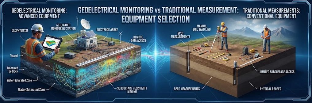
Overview:Geoelectrical Monitoring provides spatially distributed information about subsurface electrical changes, while traditional measurements track specific parameters at selected locations. This guide compares both approaches, explains how Geoelectrical Monitoring complements conventional instrumentation, and explores practical strategies for tailings dams, embankments, groundwater studies, and geotechnical risk management.
Ⅰ. What Is the Difference Between Geoelectrical Monitoring and Traditional Measurements?
Geoelectrical monitoring tracks changes in subsurface electrical properties across a defined area, while traditional measurements monitor specific physical parameters at selected locations. The two approaches provide different types of evidence and are often most useful when combined.
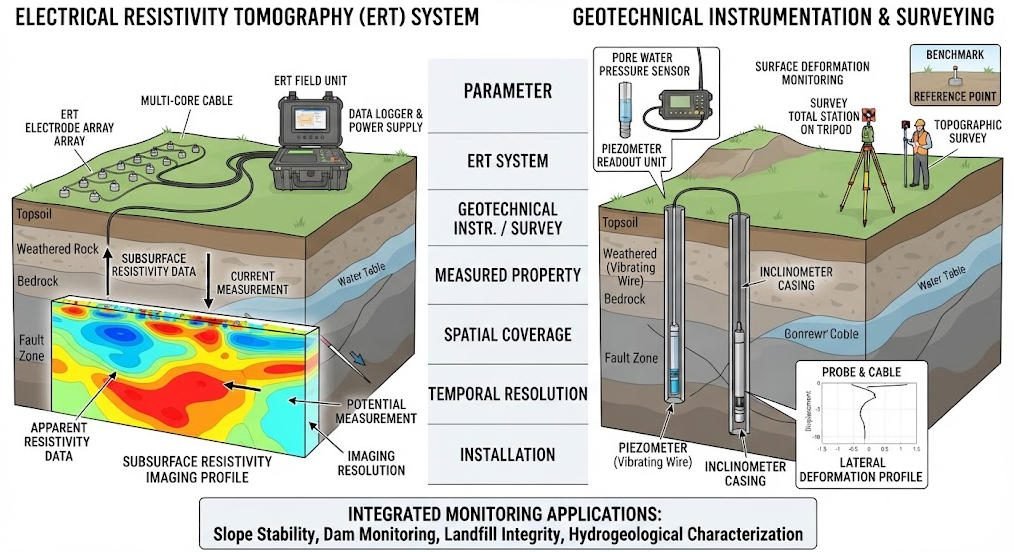
Geoelectrical monitoring commonly uses electrical resistivity tomography (ERT) to image subsurface electrical variations over time. Traditional measurements include piezometers, inclinometers, settlement markers, survey instruments, and manual inspections.
Neither approach provides a complete picture of every underground process. The appropriate choice depends on the physical parameter of interest, the spatial coverage required, and the consequences of missing a change.
1. Understanding the Two Monitoring Approaches
Geoelectrical monitoring measures electrical responses and uses inversion to estimate subsurface resistivity distributions. Repeated surveys or automated measurements can reveal how those distributions change over time.
Traditional geotechnical instrumentation measures specific physical quantities. A piezometer records pore-water pressure, an inclinometer measures lateral displacement along a borehole, and a settlement marker tracks vertical movement at a reference point.
The difference is not simply between modern and traditional technology. It is primarily a difference in measurement principle, spatial coverage, and the type of information produced.
2. What Does Each Method Measure?
| Monitoring Method | Primary Measurement | Typical Output | Main Interpretation |
|---|---|---|---|
| Electrical Resistivity Tomography | Voltage responses to injected current | Resistivity sections or 3D models | Electrical changes associated with subsurface conditions |
| Piezometer | Pore-water pressure or hydraulic head | Pressure or water-level time series | Hydraulic conditions at the installation point |
| Inclinometer | Lateral displacement | Displacement profile | Deformation along a borehole |
| Settlement Monitoring | Vertical movement | Elevation changes | Surface or structural settlement |
| Surveying Instruments | Position and displacement | Coordinates and movement vectors | Surface deformation |
| Manual Inspection | Visible conditions | Inspection records and observations | Surface signs and operational conditions |
| Groundwater Sampling | Water chemistry | Laboratory analytical results | Water quality and selected chemical indicators |
These measurements are complementary. For example, ERT may indicate a changing electrical zone, while a nearby piezometer helps determine whether hydraulic conditions changed at that location.
Ⅱ. How Does Continuous Geoelectrical Monitoring Work?
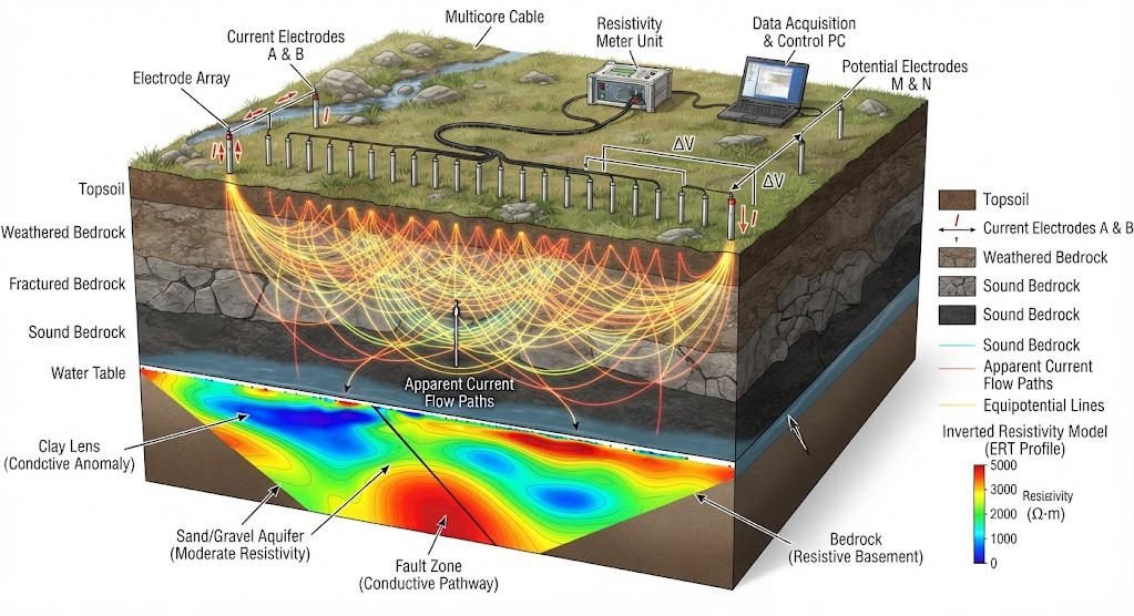
Continuous geoelectrical monitoring uses a fixed or repeatable electrode arrangement to measure electrical responses over time. Automated systems may schedule measurements, transmit data, and support time-lapse analysis.
1. Electrical Resistivity Tomography Principles
ERT injects electrical current into the ground through current electrodes and measures voltage differences using potential electrodes.
The apparent resistivity is calculated as:
ρa=KIΔV
Where:
- ρa is apparent resistivity in Ω·m.
- K is the geometric factor.
- ΔV is the measured voltage difference.
- I is the injected current.
The instrument measures electrical responses. Software then uses inversion to estimate a resistivity distribution consistent with the data and model assumptions.
2. From Repeated Measurements to Time-Lapse Imaging
A typical monitoring workflow includes:
- Install and document the electrode array.
- Collect a baseline dataset.
- Repeat measurements using a compatible configuration.
- Check data quality and acquisition consistency.
- Invert the measurements and compare successive models.
- Interpret changes alongside independent site measurements.
A time-lapse model can reveal evolving electrical patterns. It does not directly measure pore pressure, displacement, or water content unless a suitable site-specific relationship has been established.
3. Continuous Does Not Always Mean Real-Time
The term continuous monitoring can refer to scheduled automated measurements rather than uninterrupted measurement.
The actual monitoring interval depends on the electrode configuration, acquisition duration, power supply, communications, and processing workflow.
An automated system may provide faster access to data than periodic field campaigns. However, it still requires quality control, maintenance, and an appropriate interpretation process.
Ⅲ. Traditional Geotechnical Monitoring Methods
Traditional monitoring methods remain essential because they measure specific physical parameters that electrical imaging cannot directly determine.
1. Piezometers
Piezometers measure pore-water pressure or hydraulic head at an installed location. They provide direct hydraulic observations that help engineers evaluate groundwater conditions and seepage-related behavior.
Their principal limitation is spatial coverage. A piezometer represents conditions near its installation point and may not capture changes elsewhere without an adequately designed network.
2. Inclinometers
Inclinometers measure lateral displacement along a borehole. They help identify the depth and magnitude of deformation within a slope, embankment, or other geotechnical structure.
They provide deformation information that ERT cannot directly replace. Their coverage depends on borehole placement and the instrument’s measurement range.
3. Settlement and Surveying Measurements
Settlement markers, precise leveling, GNSS, and other surveying methods track surface or structural movement.
These methods are useful for identifying deformation trends and confirming whether movement is occurring. They do not directly reveal the internal distribution of moisture or resistivity.
4. Manual Inspections and Sampling
Visual inspections can identify cracks, erosion, seepage outlets, unusual wet areas, and other surface conditions.
Sampling provides material or water for laboratory analysis. Both methods supply evidence that geophysical imaging alone cannot provide.
Their effectiveness depends on inspection frequency, site accessibility, sampling design, and the quality of records.
Ⅳ. Geoelectrical Monitoring vs Traditional Measurements: A Technical Comparison
The comparison should focus on measurement capability rather than assuming that one approach is universally superior.
1. Main Differences
| Comparison Factor | Geoelectrical Monitoring | Traditional Measurements |
|---|---|---|
| Measurement Principle | Electrical response and resistivity inversion | Direct measurement of a selected physical parameter or visual condition |
| Spatial Coverage | Distributed coverage within the sensitivity region of the electrode array | Usually concentrated around instruments or inspection locations |
| Temporal Coverage | Repeated or automated electrical measurements | Continuous, scheduled, or periodic depending on the instrument |
| Primary Output | Resistivity model and time-lapse changes | Pressure, displacement, settlement, water level, or inspection records |
| Installation | Surface or borehole electrode arrays | Sensor-specific installation, boreholes, benchmarks, or inspection routes |
| Interpretation | Indirect and dependent on geological context | Often more direct for the parameter measured |
| Main Uncertainty | Non-unique inversion, electrical-property ambiguity, acquisition effects | Instrument accuracy, placement, calibration, and local representativeness |
| Best Use | Identifying spatially distributed electrical changes | Measuring specific engineering parameters |
2. Spatial Coverage and Resolution
ERT can provide spatially distributed information across a monitored section. Its sensitivity is not uniform throughout the subsurface, and resolution depends on electrode geometry, data quality, geology, and inversion assumptions.
Traditional instruments provide measurements at specific points, along boreholes, or across surveyed surfaces. Their results may be highly informative for the parameter measured but may not describe conditions between observation locations.
Spatial coverage should not be confused with accuracy. A broad electrical image does not necessarily provide more accurate information about pore pressure or deformation than a properly installed sensor.
3. Temporal Resolution and Data Continuity
Automated geoelectrical systems can repeat measurements according to a predefined schedule. Traditional instruments can also operate continuously when equipped with automatic data loggers.
The difference therefore depends on the actual system architecture, not simply on whether the method is geophysical or conventional.
For rapidly changing processes, the monitoring interval should be shorter than the timescale of the change that the project needs to detect, subject to data quality and operational constraints.
4. Direct and Indirect Measurements
Traditional sensors often measure the physical quantity they are designed to record. A piezometer measures hydraulic pressure, while a displacement sensor measures movement.
ERT measures electrical responses and estimates resistivity. Resistivity may be influenced by saturation, pore-water conductivity, temperature, clay content, and other material properties.
This distinction matters when interpreting anomalies. A resistivity change may indicate a condition requiring investigation, but it cannot independently establish the cause.
Ⅴ. Applications in Tailings Dams, Embankments, and Slopes
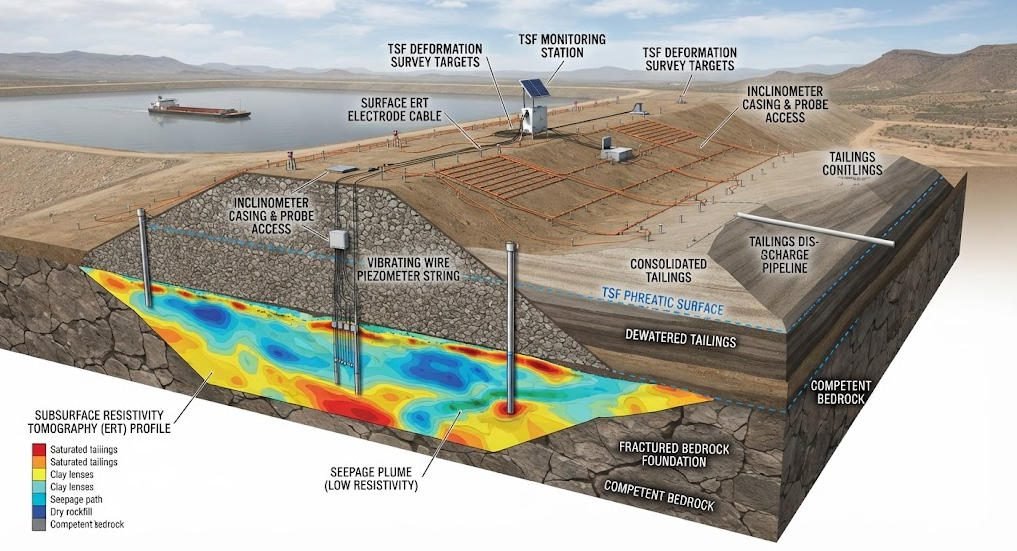
Geoelectrical monitoring can provide additional spatial information for infrastructure where underground water movement and material changes matter.
1. Tailings Dam Monitoring
Tailings storage facilities can experience changing saturation, seepage, drainage conditions, and material properties.
ERT can help map electrical variations associated with these processes. Repeated measurements may reveal where changes develop and how they evolve across a monitored section.
However, resistivity does not directly measure structural stability. Tailings facility monitoring should combine geophysical observations with pore-pressure measurements, deformation monitoring, water balance, inspections, and engineering assessment.
2. Earth Dams and Embankments
Electrical imaging can help investigate changes in moisture distribution and possible seepage-related anomalies within earth structures.
Piezometers provide direct hydraulic observations, while deformation instruments track movement. Surface inspections can identify visible signs such as wet areas, erosion, or cracking.
Combining these methods helps engineers evaluate whether an electrical anomaly corresponds to a meaningful hydraulic or geotechnical change.
3. Landslide and Slope Monitoring
ERT may help identify zones of changing moisture conditions within a slope. Inclinometers, GNSS, and other displacement instruments provide direct evidence of movement.
Rainfall, groundwater levels, and pore-water pressure measurements help establish the relationship between environmental forcing and slope response.
No single method can independently characterize every component of slope behavior. Monitoring design should reflect the failure mechanisms considered plausible for the site.
4. Groundwater and Environmental Monitoring
Repeated electrical imaging can help investigate changes associated with groundwater recharge, salinity, infiltration, and fluid migration.
Groundwater monitoring wells provide water-level measurements, while sampling provides chemical information. Geoelectrical data can complement these measurements by showing spatial patterns between observation points.
Electrical imaging cannot independently identify a specific contaminant or determine its concentration.
Ⅵ. Advantages and Limitations of Each Approach
1. Potential Advantages of Geoelectrical Monitoring
Geoelectrical monitoring can offer:
- Spatially distributed information about subsurface electrical changes.
- Repeated imaging of the same monitored section.
- Detection of evolving electrical anomalies that may not be captured by isolated point measurements.
- Reduced need for repeated manual acquisition when an automated system is suitable.
- Integration with hydrological and geotechnical datasets.
These advantages depend on site conditions, electrode installation, measurement quality, and interpretation methods.
2. Limitations of Geoelectrical Monitoring
Important limitations include:
- Resistivity is an indirect indicator of subsurface conditions.
- Different physical processes may produce similar electrical changes.
- Inversion results depend on data quality and model assumptions.
- Electrode contact and movement can affect measurement consistency.
- Automated monitoring requires power, communications, maintenance, and data validation.
- A resistivity anomaly does not automatically indicate structural damage or imminent failure.
3. Advantages and Limitations of Traditional Measurements
| Aspect | Advantages | Limitations |
|---|---|---|
| Piezometers | Direct hydraulic measurements at the sensor location | Limited spatial representation |
| Inclinometers | Direct deformation profiles along boreholes | Limited to installed boreholes and measurement geometry |
| Surveying | Measures surface or structural movement | Does not directly characterize subsurface moisture |
| Manual Inspection | Identifies visible conditions and operational issues | Depends on access, inspection frequency, and observer records |
| Sampling | Provides material or chemical evidence | Point-based and dependent on sampling design |
| Geoelectrical Monitoring | Distributed electrical imaging and time-lapse change analysis | Indirect interpretation and sensitivity limitations |
The appropriate method depends on the engineering question, not on the perceived novelty of the technology.
Ⅶ. How to Integrate Geoelectrical and Traditional Monitoring
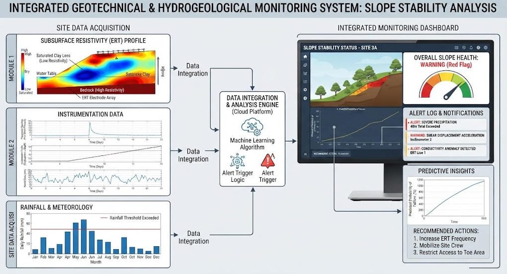
An integrated monitoring system combines measurements that answer different questions about the same site.
1. Build a Monitoring Matrix
Start by linking each potential hazard or process to a measurable parameter.
| Process or Concern | Geoelectrical Contribution | Traditional Measurement | Interpretation Goal |
|---|---|---|---|
| Changing saturation | Spatial resistivity variation | Piezometer, moisture sensor | Evaluate water-related changes |
| Potential seepage | Electrical anomaly distribution | Seepage flow, water level, piezometer | Investigate possible seepage pathways |
| Slope deformation | Electrical changes associated with subsurface conditions | Inclinometer, GNSS | Relate internal changes to movement |
| Settlement | Possible electrical changes in affected materials | Settlement markers, surveying | Assess surface deformation |
| Groundwater migration | Resistivity changes over time | Wells, water-level sensors, sampling | Evaluate hydraulic and chemical conditions |
2. Synchronize Data
The datasets should use compatible timestamps and documented measurement intervals.
For example, electrical measurements can be compared with rainfall, groundwater levels, pore-water pressure, and displacement records.
Data synchronization helps engineers investigate whether electrical changes occurred before, during, or after changes in other monitored parameters.
Temporal association alone does not prove causation. Interpretation should consider the site’s geology and expected physical processes.
3. Establish Baselines and Thresholds
A baseline should characterize normal conditions and expected variability.
Thresholds should be defined according to the monitored parameter, site-specific behavior, engineering criteria, and the consequences of a missed change.
Electrical thresholds should not be copied directly from another site without validation. Resistivity values depend on geology, pore-water chemistry, temperature, and measurement configuration.
4. Define an Escalation Workflow
A monitoring workflow should specify what happens when an anomaly appears.
A typical process includes:
- Check measurement quality and system status.
- Compare the anomaly with baseline behavior.
- Review related hydrological and geotechnical measurements.
- Conduct targeted inspection or additional measurements.
- Have qualified personnel assess the evidence.
- Apply the site’s established response procedures when required.
This approach helps distinguish instrument artifacts from changes that warrant engineering attention.
Ⅷ. How to Choose a Monitoring Method
The selection process should begin with the parameter that must be measured and the type of decision the data will support.
1. Select According to the Monitoring Objective
| Monitoring Objective | Primary Method to Consider | Complementary Method |
|---|---|---|
| Measure pore-water pressure | Piezometer | ERT for spatial electrical context |
| Measure lateral deformation | Inclinometer | ERT for subsurface electrical changes |
| Track surface settlement | Surveying or settlement markers | ERT where electrical imaging is relevant |
| Map electrical changes across a section | ERT | Piezometers and field observations |
| Investigate groundwater chemistry | Sampling and laboratory analysis | ERT for spatial electrical context |
| Monitor multiple potential failure mechanisms | Integrated monitoring network | Geoelectrical, hydraulic, and deformation sensors |
2. Evaluate Site Conditions
Before selecting equipment, assess:
- Geological and hydrogeological conditions.
- Target depth and geometry.
- Site accessibility and electrode installation options.
- Expected rate of change.
- Required spatial and temporal resolution.
- Power and communications availability.
- Environmental exposure and maintenance access.
- Data processing and reporting requirements.
3. Compare Lifecycle Costs
Monitoring costs extend beyond the initial equipment purchase.
| Cost Component | Geoelectrical Monitoring | Traditional Monitoring |
|---|---|---|
| Initial Installation | Electrode arrays, cabling, measurement system | Sensors, boreholes, benchmarks, installation |
| Routine Operation | Power, communications, software, inspections | Data logging, site visits, calibration |
| Data Processing | Electrical data processing and inversion | Sensor-specific processing and validation |
| Maintenance | Electrodes, cables, electronics, communications | Sensors, boreholes, cables, reference points |
| Additional Investigation | Targeted surveys and supporting measurements | Additional sensors, sampling, inspections |
The total cost depends on site size, monitoring frequency, accessibility, system complexity, and service requirements. A reliable cost comparison should use the same monitoring objective and project duration.
Ⅸ. Data Quality, Uncertainty, and Risk Management
Monitoring data support engineering decisions only when their limitations are understood.
1. Data Quality for ERT
Important quality-control checks include:
- Electrode contact and stability.
- Consistency of electrode positions and configurations.
- Repeatability of measurements.
- Instrument condition and calibration.
- Environmental conditions during acquisition.
- Data completeness and inversion quality.
2. Data Quality for Traditional Instruments
Traditional instruments also require quality assurance.
Piezometers need suitable installation and calibration. Inclinometers require consistent measurement procedures and stable casing. Surveying systems need reliable reference points and documented measurement methods.
A monitoring network should record instrument status, maintenance, and data gaps.
3. Risk Interpretation
An anomaly should be interpreted within a site-specific conceptual model.
Geoelectrical monitoring may identify a change in electrical properties. Traditional instruments may establish whether pressure, displacement, or settlement changed at a monitored location.
Engineering assessment should consider the combined evidence and the site’s potential failure mechanisms. Monitoring systems should support, rather than replace, formal safety management and qualified engineering judgment.
Ⅹ. Geoelectrical Monitoring Equipment and Geotech Solutions
A geoelectrical monitoring system typically includes a resistivity measurement instrument, electrodes, cables, switching hardware where required, data acquisition, and processing software.
The appropriate configuration depends on whether the project needs periodic repeat surveys, multi-electrode imaging, or a long-term automated arrangement.
Geotech’s electrical exploration resources can support the evaluation of resistivity and IP equipment for related investigation tasks.
Relevant resources include:
- Electrical Imaging: ERT and VES
- What Are Resistivity Meters?
- Induced Polarization Method
- High Power IP System
- WDA-1 DC Meter
- WGMD-9 Distributed System
For permanent monitoring, confirm whether the selected equipment supports the required automation, electrode switching, remote communications, data integration, and long-term operating conditions. Product suitability should be established through a project-specific technical review.
Ⅺ. Conclusion
Geoelectrical monitoring and traditional measurements provide different but complementary information.
ERT offers spatially distributed electrical imaging and can help track changes in subsurface conditions. Traditional instruments provide direct measurements of parameters such as pore-water pressure, displacement, settlement, and groundwater level.
The appropriate monitoring strategy depends on the physical process, required coverage, response time, and engineering decision. For complex sites such as tailings dams, embankments, and slopes, an integrated system can combine electrical imaging with hydraulic, deformation, and visual observations.
The objective is not to replace one technology with another. It is to build a monitoring program that produces reliable, interpretable evidence for site-specific engineering decisions.
Related Articles
| Title | Core Content | URL |
|---|---|---|
| Electrical Imaging: ERT & VES | Electrical resistivity imaging and vertical electrical sounding for subsurface investigation | https://geotechcn.net/service/electrical-imaging-ert-ves/ |
| What Are Resistivity Meters? | Resistivity meter principles, measurement methods, and applications | https://geotechcn.net/service/what-are-resistivity-meters/ |
| Induced Polarization Method | IP principles, measurement techniques, and exploration applications | https://geotechcn.net/service/induced-polarization-ip/ |
| Geophysical Surveying Explained | Overview of geophysical methods and subsurface exploration | https://geotechcn.net/service/geophysical-surveying-explained/ |
| Geophysical Methods Demystified | Fundamentals of electrical, magnetic, seismic, and other geophysical methods | https://geotechcn.net/service/geophysical-methods-demystified/ |
| High Power IP System | High-power induced polarization instrumentation and applications | https://geotechcn.net/products/electrical-instrument/high-power-ip-system/ |
| WDA-1 DC Meter | DC electrical measurement equipment | https://geotechcn.net/products/electrical-instrument/wda-1-dc-meter/ |
| WGMD-9 Distributed System | Distributed geophysical measurement system | https://geotechcn.net/products/electrical-instrument/wgmd-9-distributed-system/ |
Reference Sources
| Title | Core Content | URL |
|---|---|---|
| A Review on Applications of Time-Lapse Electrical Resistivity Tomography Over the Last 30 Years | Review of time-lapse ERT applications, long-term monitoring, and technical challenges | https://doi.org/10.1007/s10712-022-09731-2 |
| Advances in Interpretation of Subsurface Processes with Time-Lapse Electrical Imaging — USGS | Time-lapse electrical imaging, subsurface processes, and interpretation | https://www.usgs.gov/publications/advances-interpretation-subsurface-processes-time-lapse-electrical-imaging |
| Monitoring Groundwater–Surface Water Interaction Using Time-Series and Time-Frequency Analysis — USGS | Electrical imaging for groundwater–surface-water interactions | https://pubs.usgs.gov/publication/70074333 |
| Experimenting a Permanent Geoelectrical Monitoring System for Stability Assessment of Levees | Permanent geoelectrical monitoring for levee stability and seepage-related assessment | https://www.researchgate.net/publication/321874973_Experimenting_a_permanent_geoelectrical_monitoring_system_for_stability_assessment_of_levees |
| ICOLD — International Commission on Large Dams | Technical resources on dam safety, surveillance, and monitoring practices | https://www.icold-cigb.org/ |
FAQ
Q1. What is the difference between geoelectrical monitoring and traditional measurements?
Geoelectrical monitoring uses electrical measurements to estimate subsurface resistivity changes across a monitored area. Traditional measurements record specific parameters such as pore-water pressure, displacement, or settlement. The methods provide different evidence and are often combined to improve site characterization and monitoring.
Q2. Can geoelectrical monitoring replace piezometers and inclinometers?
No. ERT provides indirect information about electrical changes, while piezometers measure hydraulic pressure and inclinometers measure deformation. Geoelectrical monitoring can help identify areas for further investigation, but conventional instruments remain necessary when direct measurements of pressure or displacement are required.
Q3. What are the advantages of continuous geoelectrical monitoring?
Continuous or automated geoelectrical monitoring can provide repeated spatially distributed information about subsurface electrical changes. It may help identify evolving anomalies between manual survey campaigns. Its effectiveness depends on electrode stability, data quality, monitoring frequency, and appropriate interpretation.
Q4. Is ERT suitable for tailings dam monitoring?
ERT can help investigate electrical changes associated with moisture distribution and possible seepage-related processes in tailings facilities. It does not directly measure structural stability or confirm failure mechanisms. A suitable monitoring program combines ERT with pore-pressure measurements, deformation monitoring, inspections, and engineering assessment.
Q5. How do I choose between geoelectrical monitoring and traditional instruments?
Start with the physical parameter and engineering decision. Use geoelectrical monitoring when spatially distributed electrical changes are relevant. Use traditional instruments for direct measurements of pressure, displacement, or settlement. For complex sites, an integrated monitoring system may provide the most complete evidence.